Component – XL1509 – 2A 40V 150KHz Step-Down Converter
XL1509
The XL1509 is a 150 KHz fixed frequency PWM buck (step-down) DC/DC converter, capable of driving a 2A load with high efficiency, low ripple and excellent line and load regulation. Requiring a minimum number of external components, the regulator is simple to use and include nternal frequency compensation and a fixed-frequency oscillator.The PWM control circuit is able to adjust the duty ratio linearly from 0 to 100%. An enable function, an over current protection function is built inside. When second current limit function happens, the operation frequency will be reduced from 150KHz to 50KHz. An internal compensation block is built in to minimize external component count.
Features & Benefits
Wide 4.5V to 40V Input Voltage Range
3.3V,5V,12V, and adjustable versions
Output Adjustable from 1.23V to 37V
Maximum Duty Cycle 100%
Minimum Drop Out 1.5V
Fixed 150KHz Switching Frequency
2A Constant Output Current Capability
Internal Optimize Power Transistor
High efficiency
Excellent line and load regulation
TTL shutdown capability
ON/OFF pin with hysteresis function
Built in thermal shutdown function
Built in current limit function
Built in second current limit function
Available in SOP8 package
Schema
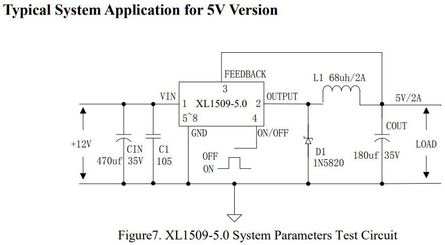
From the datasheet a 5V fixed version:
Translated from a Chinese website:
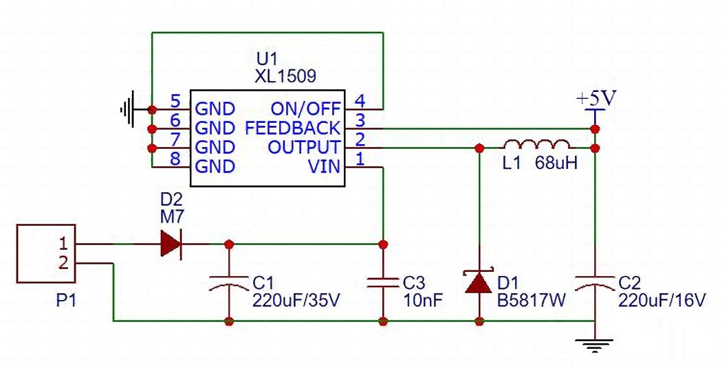
In the manual of XL1509, its classic circuit diagram has been given, and the above diagram is also connected according to the diagram on the manual. However, many people want to know the principle, I will introduce it in detail below.
D2 uses ordinary diode M7, which is the patch version of the in-line component IN4007. Its function is to prevent the reverse connection of the power supply. When you accidentally reverse the positive and negative connections of the power supply, it will not burn the circuit board.
The role of C1 and C3 is to filter the power supply, which is to remove the noise of the input power supply. C1 does not necessarily have to use 220uF, it is possible to use 100uF or 470uF. C3 can use 10nF or 100nF. The key is that the withstand voltage of C1 and C3 must be greater than the power supply voltage for the circuit board.
L1 uses 68uH inductance. The function is to filter the noise of the power supply 5V output.
D1 is Schottky diode B5817W, where the function is freewheeling. Because the DC-DC chip is based on the principle of switching power supply, the diode plays a freewheeling function when the MOS tube in the chip is turned off. The current flows through the diode and then is output from the inductor.