Mechanica Firmware – GRBL info – Configuratie
![]()
Informatie (ENG)
source: https://github.com/gnea/grbl/wiki/Grbl-v1.1-Configuration
Getting Started
First, connect to Grbl using the serial terminal of your choice.
Set the baud rate to 115200 as 8-N-1 (8-bits, no parity, and 1-stop bit.)
Once connected you should get the Grbl-prompt, which looks like this:
|
1 2 |
Grbl 1.1f ['$' for help] |
Type $ and press enter to have Grbl print a help message. You should not see any local echo of the $ and enter. Grbl should respond with:
|
1 2 |
[HLP:$$ $# $G $I $N $x=val $Nx=line $J=line $SLP $C $X $H ~ ! ? ctrl-x] |
The ‘$’-commands are Grbl system commands used to tweak the settings, view or change Grbl’s states and running modes, and start a homing cycle. The last four non-‘$’ commands are realtime control commands that can be sent at anytime, no matter what Grbl is doing. These either immediately change Grbl’s running behavior or immediately print a report of the important realtime data like current position (aka DRO).
Grbl Settings
$$ – View Grbl settings
To view the settings, type $$ and press enter after connecting to Grbl. Grbl should respond with a list of the current system settings, as shown in the example below. All of these settings are persistent and kept in EEPROM, so if you power down, these will be loaded back up the next time you power up your Arduino.
The x of $x=val indicates a particular setting, while val is the setting value. In prior versions of Grbl, each setting had a description next to it in () parentheses, but Grbl v1.1+ no longer includes them unfortunately. This was done to free up precious flash memory to add the new features available in v1.1. However, most good GUIs will help out by attaching descriptions for you, so you know what you are looking at.
$x=val – Save Grbl setting
The $x=val command saves or alters a Grbl setting, which can be done manually by sending this command when connected to Grbl through a serial terminal program, but most Grbl GUIs will do this for you as a user-friendly feature.
To manually change e.g. the microseconds step pulse option to 10us you would type this, followed by an enter:
|
1 2 |
$0=10 |
If everything went well, Grbl will respond with an ‘ok’ and this setting is stored in EEPROM and will be retained forever or until you change them. You can check if Grbl has received and stored your setting correctly by typing $$ to view the system settings again.
Grbl’s $x=val settings and what they mean
NOTE: From Grbl v0.9 to Grbl v1.1, only $10 status reports changed and new $30/ $31 spindle rpm max/min and $32 laser mode settings were added. Everything else is the same.
$0 – Step pulse, microseconds
Stepper drivers are rated for a certain minimum step pulse length. Check the data sheet or just try some numbers. You want the shortest pulses the stepper drivers can reliably recognize. If the pulses are too long, you might run into trouble when running the system at very high feed and pulse rates, because the step pulses can begin to overlap each other. We recommend something around 10 microseconds, which is the default value.
$1 – Step idle delay, milliseconds
Every time your steppers complete a motion and come to a stop, Grbl will delay disabling the steppers by this value. OR, you can always keep your axes enabled (powered so as to hold position) by setting this value to the maximum 255 milliseconds. Again, just to repeat, you can keep all axes always enabled by setting $1=255.
The stepper idle lock time is the time length Grbl will keep the steppers locked before disabling. Depending on the system, you can set this to zero and disable it. On others, you may need 25-50 milliseconds to make sure your axes come to a complete stop before disabling. This is to help account for machine motors that do not like to be left on for long periods of time without doing something. Also, keep in mind that some stepper drivers don’t remember which micro step they stopped on, so when you re-enable, you may witness some ‘lost’ steps due to this. In this case, just keep your steppers enabled via $1=255.
$2 – Step port invert, mask
This setting inverts the step pulse signal. By default, a step signal starts at normal-low and goes high upon a step pulse event. After a step pulse time set by $0, the pin resets to low, until the next step pulse event. When inverted, the step pulse behavior switches from normal-high, to low during the pulse, and back to high. Most users will not need to use this setting, but this can be useful for certain CNC-stepper drivers that have peculiar requirements. For example, an artificial delay between the direction pin and step pulse can be created by inverting the step pin.
This invert mask setting is a value which stores the axes to invert as bit flags. You really don’t need to completely understand how it works. You simply need to enter the settings value for the axes you want to invert. For example, if you want to invert the X and Z axes, you’d send $2=5 to Grbl and the setting should now read $2=5 (step port invert mask:00000101).
| Setting Value | Mask | Invert X | Invert Y | Invert Z |
|---|---|---|---|---|
| 0 | 00000000 | N | N | N |
| 1 | 00000001 | Y | N | N |
| 2 | 00000010 | N | Y | N |
| 3 | 00000011 | Y | Y | N |
| 4 | 00000100 | N | N | Y |
| 5 | 00000101 | Y | N | Y |
| 6 | 00000110 | N | Y | Y |
| 7 | 00000111 | Y | Y | Y |
$3 – Direction port invert, mask
This setting inverts the direction signal for each axis. By default, Grbl assumes that the axes move in a positive direction when the direction pin signal is low, and a negative direction when the pin is high. Often, axes don’t move this way with some machines. This setting will invert the direction pin signal for those axes that move the opposite way.
This invert mask setting works exactly like the step port invert mask and stores which axes to invert as bit flags. To configure this setting, you simply need to send the value for the axes you want to invert. Use the table above. For example, if want to invert the Y axis direction only, you’d send $3=2 to Grbl and the setting should now read $3=2 (dir port invert mask:00000010)
$4 – Step enable invert, boolean
By default, the stepper enable pin is high to disable and low to enable. If your setup needs the opposite, just invert the stepper enable pin by typing $4=1. Disable with $4=0. (May need a power cycle to load the change.)
$5 – Limit pins invert, boolean
By default, the limit pins are held normally-high with the Arduino’s internal pull-up resistor. When a limit pin is low, Grbl interprets this as triggered. For the opposite behavior, just invert the limit pins by typing $5=1. Disable with $5=0. You may need a power cycle to load the change.
NOTE: For more advanced usage, the internal pull-up resistor on the limit pins may be disabled in config.h.
$6 – Probe pin invert, boolean
By default, the probe pin is held normally-high with the Arduino’s internal pull-up resistor. When the probe pin is low, Grbl interprets this as triggered. For the opposite behavior, just invert the probe pin by typing $6=1. Disable with $6=0. You may need a power cycle to load the change.
$10 – Status report, mask
This setting determines what Grbl real-time data it reports back to the user when a ‘?’ status report is sent. This data includes current run state, real-time position, real-time feed rate, pin states, current override values, buffer states, and the g-code line number currently executing (if enabled through compile-time options).
By default, the new report implementation in Grbl v1.1+ will include just about everything in the standard status report. A lot of the data is hidden and will appear only if it changes. This increases efficiency dramatically over of the old report style and allows you to get faster updates and still get more data about your machine. The interface documentation outlines how it works and most of it applies only to GUI developers or the curious.
To keep things simple and consistent, Grbl v1.1 has only two reporting options. These are primarily here just for users and developers to help set things up.
- Position type may be specified to show either machine position (
MPos:) or work position (WPos:), but no longer both at the same time. Enabling work position is useful in certain scenarios when Grbl is being directly interacted with through a serial terminal, but machine position reporting should be used by default. - Usage data of Grbl’s planner and serial RX buffers may be enabled. This shows the number of blocks or bytes available in the respective buffers. This is generally used to helps determine how Grbl is performing when testing out a streaming interface. This should be disabled by default.
Use the table below enables and disable reporting options. Simply add the values listed of what you’d like to enable, then save it by sending Grbl your setting value. For example, the default report with machine position and no buffer data reports setting is $10=1. If work position and buffer data are desired, the setting will be $10=2.
| Report Type | Value | Description |
|---|---|---|
| Position Type | 0 | Enable WPos: Disable MPos:. |
| Position Type | 1 | Enable MPos:. Disable WPos:. |
| Buffer Data | 2 | Enabled Buf: field appears with planner and serial RX available buffer. |
$11 – Junction deviation, mm
Junction deviation is used by the acceleration manager to determine how fast it can move through line segment junctions of a G-code program path. For example, if the G-code path has a sharp 10 degree turn coming up and the machine is moving at full speed, this setting helps determine how much the machine needs to slow down to safely go through the corner without losing steps.
How we calculate it is a bit complicated, but, in general, higher values gives faster motion through corners, while increasing the risk of losing steps and positioning. Lower values makes the acceleration manager more careful and will lead to careful and slower cornering. So if you run into problems where your machine tries to take a corner too fast, decrease this value to make it slow down when entering corners. If you want your machine to move faster through junctions, increasethis value to speed it up. For curious people, hit this link to read about Grbl’s cornering algorithm, which accounts for both velocity and junction angle with a very simple, efficient, and robust method.
$12 – Arc tolerance, mm
Grbl renders G2/G3 circles, arcs, and helices by subdividing them into teeny tiny lines, such that the arc tracing accuracy is never below this value. You will probably never need to adjust this setting, since 0.002mm is well below the accuracy of most all CNC machines. But if you find that your circles are too crude or arc tracing is performing slowly, adjust this setting. Lower values give higher precision but may lead to performance issues by overloading Grbl with too many tiny lines. Alternately, higher values traces to a lower precision, but can speed up arc performance since Grbl has fewer lines to deal with.
For the curious, arc tolerance is defined as the maximum perpendicular distance from a line segment with its end points lying on the arc, aka a chord. With some basic geometry, we solve for the length of the line segments to trace the arc that satisfies this setting. Modeling arcs in this way is great, because the arc line segments automatically adjust and scale with length to ensure optimum arc tracing performance, while never losing accuracy.
$13 – Report inches, boolean
Grbl has a real-time positioning reporting feature to provide a user feedback on where the machine is exactly at that time, as well as, parameters for coordinate offsets and probing. By default, it is set to report in mm, but by sending a $13=1 command, you send this boolean flag to true and these reporting features will now report in inches. $13=0 to set back to mm.
$20 – Soft limits, boolean
Soft limits is a safety feature to help prevent your machine from traveling too far and beyond the limits of travel, crashing or breaking something expensive. It works by knowing the maximum travel limits for each axis and where Grbl is in machine coordinates. Whenever a new G-code motion is sent to Grbl, it checks whether or not you accidentally have exceeded your machine space. If you do, Grbl will issue an immediate feed hold wherever it is, shutdown the spindle and coolant, and then set the system alarm indicating the problem. Machine position will be retained afterwards, since it’s not due to an immediate forced stop like hard limits.
NOTE: Soft limits requires homing to be enabled and accurate axis maximum travel settings, because Grbl needs to know where it is. $20=1 to enable, and $20=0 to disable.
$21 – Hard limits, boolean
Hard limit work basically the same as soft limits, but use physical switches instead. Basically you wire up some switches (mechanical, magnetic, or optical) near the end of travel of each axes, or where ever you feel that there might be trouble if your program moves too far to where it shouldn’t. When the switch triggers, it will immediately halt all motion, shutdown the coolant and spindle (if connected), and go into alarm mode, which forces you to check your machine and reset everything.
To use hard limits with Grbl, the limit pins are held high with an internal pull-up resistor, so all you have to do is wire in a normally-open switch with the pin and ground and enable hard limits with $21=1. (Disable with $21=0.) We strongly advise taking electric interference prevention measures. If you want a limit for both ends of travel of one axes, just wire in two switches in parallel with the pin and ground, so if either one of them trips, it triggers the hard limit.
Keep in mind, that a hard limit event is considered to be critical event, where steppers immediately stop and will have likely have lost steps. Grbl doesn’t have any feedback on position, so it can’t guarantee it has any idea where it is. So, if a hard limit is triggered, Grbl will go into an infinite loop ALARM mode, giving you a chance to check your machine and forcing you to reset Grbl. Remember it’s a purely a safety feature.
$22 – Homing cycle, boolean
Ahh, homing. For those just initiated into CNC, the homing cycle is used to accurately and precisely locate a known and consistent position on a machine every time you start up your Grbl between sessions. In other words, you know exactly where you are at any given time, every time. Say you start machining something or are about to start the next step in a job and the power goes out, you re-start Grbl and Grbl has no idea where it is due to steppers being open-loop control. You’re left with the task of figuring out where you are. If you have homing, you always have the machine zero reference point to locate from, so all you have to do is run the homing cycle and resume where you left off.
To set up the homing cycle for Grbl, you need to have limit switches in a fixed position that won’t get bumped or moved, or else your reference point gets messed up. Usually they are setup in the farthest point in +x, +y, +z of each axes. Wire your limit switches in with the limit pins, add a recommended RC-filter to help reduce electrical noise, and enable homing. If you’re curious, you can use your limit switches for both hard limits AND homing. They play nice with each other.
Prior to trying the homing cycle for the first time, make sure you have setup everything correctly, otherwise homing may behave strangely. First, ensure your machine axes are moving in the correct directions per Cartesian coordinates (right-hand rule). If not, fix it with the $3 direction invert setting. Second, ensure your limit switch pins are not showing as ‘triggered’ in Grbl’s status reports. If are, check your wiring and settings. Finally, ensure your $13x max travel settings are somewhat accurate (within 20%), because Grbl uses these values to determine how far it should search for the homing switches.
By default, Grbl’s homing cycle moves the Z-axis positive first to clear the workspace and then moves both the X and Y-axes at the same time in the positive direction. To set up how your homing cycle behaves, there are more Grbl settings down the page describing what they do (and compile-time options as well.)
Also, one more thing to note, when homing is enabled. Grbl will lock out all G-code commands until you perform a homing cycle. Meaning no axes motions, unless the lock is disabled ($X) but more on that later. Most, if not all CNC controllers, do something similar, as it is mostly a safety feature to prevent users from making a positioning mistake, which is very easy to do and be saddened when a mistake ruins a part. If you find this annoying or find any weird bugs, please let us know and we’ll try to work on it so everyone is happy. :)
NOTE: Check out config.h for more homing options for advanced users. You can disable the homing lockout at startup, configure which axes move first during a homing cycle and in what order, and more.
$23 – Homing dir invert, mask
By default, Grbl assumes your homing limit switches are in the positive direction, first moving the z-axis positive, then the x-y axes positive before trying to precisely locate machine zero by going back and forth slowly around the switch. If your machine has a limit switch in the negative direction, the homing direction mask can invert the axes’ direction. It works just like the step port invert and direction port invert masks, where all you have to do is send the value in the table to indicate what axes you want to invert and search for in the opposite direction.
$24 – Homing feed, mm/min
The homing cycle first searches for the limit switches at a higher seek rate, and after it finds them, it moves at a slower feed rate to home into the precise location of machine zero. Homing feed rate is that slower feed rate. Set this to whatever rate value that provides repeatable and precise machine zero locating.
$25 – Homing seek, mm/min
Homing seek rate is the homing cycle search rate, or the rate at which it first tries to find the limit switches. Adjust to whatever rate gets to the limit switches in a short enough time without crashing into your limit switches if they come in too fast.
$26 – Homing debounce, milliseconds
Whenever a switch triggers, some of them can have electrical/mechanical noise that actually ‘bounce’ the signal high and low for a few milliseconds before settling in. To solve this, you need to debounce the signal, either by hardware with some kind of signal conditioner or by software with a short delay to let the signal finish bouncing. Grbl performs a short delay, only homing when locating machine zero. Set this delay value to whatever your switch needs to get repeatable homing. In most cases, 5-25 milliseconds is fine.
$27 – Homing pull-off, mm
To play nice with the hard limits feature, where homing can share the same limit switches, the homing cycle will move off all of the limit switches by this pull-off travel after it completes. In other words, it helps to prevent accidental triggering of the hard limit after a homing cycle. Make sure this value is large enough to clear the limit switch. If not, Grbl will throw an alarm error for failing to clear it.
$30 – Max spindle speed, RPM
This sets the spindle speed for the maximum 5V PWM pin output. For example, if you want to set 10000rpm at 5V, program $30=10000. For 255rpm at 5V, program $30=255. If a program tries to set a higher spindle RPM greater than the $30 max spindle speed, Grbl will just output the max 5V, since it can’t go any faster. By default, Grbl linearly relates the max-min RPMs to 5V-0.02V PWM pin output in 255 equally spaced increments. When the PWM pin reads 0V, this indicates spindle disabled. Note that there are additional configuration options are available in config.h to tweak how this operates.
$31 – Min spindle speed, RPM
This sets the spindle speed for the minimum 0.02V PWM pin output (0V is disabled). Lower RPM values are accepted by Grbl but the PWM output will not go below 0.02V, except when RPM is zero. If zero, the spindle is disabled and PWM output is 0V.
$32 – Laser mode, boolean
When enabled, Grbl will move continuously through consecutive G1, G2, or G3 motion commands when programmed with a S spindle speed (laser power). The spindle PWM pin will be updated instantaneously through each motion without stopping. Please read the GRBL laser documentation and your laser device documentation prior to using this mode. Lasers are very dangerous. They can instantly damage your vision permanantly and cause fires. Grbl does not assume any responsibility for any issues the firmware may cause, as defined by its GPL license.
When disabled, Grbl will operate as it always has, stopping motion with every S spindle speed command. This is the default operation of a milling machine to allow a pause to let the spindle change speeds.
$100, $101 and $102 – [X,Y,Z] steps/mm
Grbl needs to know how far each step will take the tool in reality. To calculate steps/mm for an axis of your machine you need to know:
- The mm traveled per revolution of your stepper motor. This is dependent on your belt drive gears or lead screw pitch.
- The full steps per revolution of your steppers (typically 200)
- The microsteps per step of your controller (typically 1, 2, 4, 8, or 16). Tip: Using high microstep values (e.g., 16) can reduce your stepper motor torque, so use the lowest that gives you the desired axis resolution and comfortable running properties.
The steps/mm can then be calculated like this: steps_per_mm = (steps_per_revolution*microsteps)/mm_per_rev
Compute this value for every axis and write these settings to Grbl.
$110, $111 and $112 – [X,Y,Z] Max rate, mm/min
This sets the maximum rate each axis can move. Whenever Grbl plans a move, it checks whether or not the move causes any one of these individual axes to exceed their max rate. If so, it’ll slow down the motion to ensure none of the axes exceed their max rate limits. This means that each axis has its own independent speed, which is extremely useful for limiting the typically slower Z-axis.
The simplest way to determine these values is to test each axis one at a time by slowly increasing max rate settings and moving it. For example, to test the X-axis, send Grbl something like G0 X50with enough travel distance so that the axis accelerates to its max speed. You’ll know you’ve hit the max rate threshold when your steppers stall. It’ll make a bit of noise, but shouldn’t hurt your motors. Enter a setting a 10-20% below this value, so you can account for wear, friction, and the mass of your workpiece/tool. Then, repeat for your other axes.
NOTE: This max rate setting also sets the G0 seek rates.
$120, $121, $122 – [X,Y,Z] Acceleration, mm/sec^2
This sets the axes acceleration parameters in mm/second/second. Simplistically, a lower value makes Grbl ease slower into motion, while a higher value yields tighter moves and reaches the desired feed rates much quicker. Much like the max rate setting, each axis has its own acceleration value and are independent of each other. This means that a multi-axis motion will only accelerate as quickly as the lowest contributing axis can.
Again, like the max rate setting, the simplest way to determine the values for this setting is to individually test each axis with slowly increasing values until the motor stalls. Then finalize your acceleration setting with a value 10-20% below this absolute max value. This should account for wear, friction, and mass inertia. We highly recommend that you dry test some G-code programs with your new settings before committing to them. Sometimes the loading on your machine is different when moving in all axes together.
$130, $131, $132 – [X,Y,Z] Max travel, mm
This sets the maximum travel from end to end for each axis in mm. This is only useful if you have soft limits (and homing) enabled, as this is only used by Grbl’s soft limit feature to check if you have exceeded your machine limits with a motion command.
Quick Guide to Setting Up Your Machine for the First Time
Grbl’s default configuration is intentionally very generic to help ensure users can see successful motion without having to tweak settings. Generally, the first thing you’ll want to do is get your stepper motors running, usually without it connected to the CNC. Wire Grbl to your stepper drivers and stepper motors according to your manufacturer guidelines. Connect to Grbl through a serial terminal or one of many Grbl GUIs. Send some G1 or G0 commands to Grbl. You should see your stepper motor rotating. If you are having trouble with your stepper motors, try the following:
- Ensure everything is wired and powered correctly per your stepper driver manufacturer guidelines.
- If your steppers are mounted in your CNC already, ensure your axes move freely and don’t obviously bind. If you can’t easily tell, try removing your steppers and check if they run under no load.
- Ensure your stepper motors and axes linear mechanisms are all tight and secure. Small set screws on drivetrain components becoming loose is a very common problem. Re-tighten and try applying some non-permenant thread locker (Loctite blue) if it continually loosens.
- For more difficult issues, try the process of elimination to quickly isolate the problem. Start by disconnecting everything from the Arduino. Test if Grbl is operating ok by itself. Then, add one thing at a time and test.
- If your steppers are powered and making a grinding noise when trying to move, try lowering the ‘$’ acceleration and max rate settings. This sound is a sign that your steppers is losing steps and not able to keep up due too much torque load or going too fast.
- Grbl’s default step pulse settings cover the vast majority of stepper drivers on the market. While very uncommon, check these settings if you are still experiencing problems or have a unusual setup.
Next, you will need to make sure your machine is moving in the correct directions according to a Cartesian(XYZ) coordinate frame and satisfies the right-hand rule, as shown:
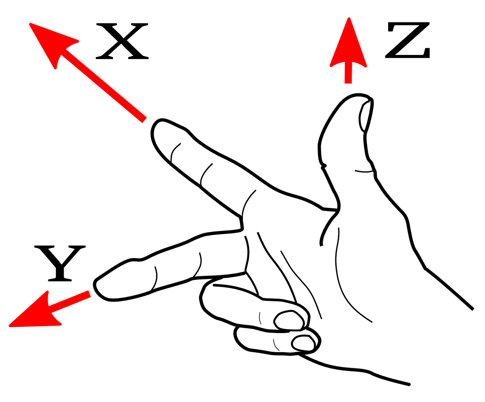
Mount your stepper motors into your CNC, if you haven’t already done so. Send Grbl some motion commands, such as G91 G0 X1 or G91 G0 X-1, which will move the x-axis +1mm and -1mm, respectively. Check all axes. If an axis is not moving correctly, alter the $3 direction port mask setting to invert the direction.
If you are unfamiliar with how coordinate frames are setup on CNC machines, see this great diagram by LinuxCNC. Just keep in mind that motions are relative to the tool. So on a typical CNC gantry router, the tool will move rather than the fixed table. If the x-axis is aligned positive to the right, a positive motion command will move the tool to the right. Whereas, a moving table with a fixed tool will move the table to the left for the same command, because the tool is moving to the right relative to the table.
Finally, tune your settings to get close to your desired or max performance. Start by ensuring your $100,$101, and $102 axes step/mm settings are correct for your setup. This is dependent on your stepper increments, micro steps on your driver, and mechanical parameters. There are multiple resources online to show you how to compute this for your particular machine, if your machine manufacturer has not supplied this for you. Tweak your $12x acceleration and $11x max rate settings to improve performance. Set to no greater than 80% of absolute max to account for inertia, cutting forces, and motor torque reductions with speed. Set your $13x max travel settings if you plan on using homing or soft limits. It’s recommended to enter something approximately close to actual travel now to avoid problems in the future.
At this point, you’re pretty much ready to get going! Grbl can now move your CNC machine and run g-code jobs. If you need to add more features, such as limit switches for homing or hard limits or spindle/laser control. There are other Wiki pages to help you that. Good luck and have fun!