3D Printer – Heated bed – Reprap, Mendel
![]()
Informatie (ENG):
Previously the accepted method was to cover the PCB heatbed with kapton tape, degrease it and print. An alternative method that has become popular (as of January 2015) is to use a sheet of 3mm borosilicate glass, held using bulldog clips (see the Discussion tab). Adherence of the printed object to the glass is helped by spraying the clean glass with hair lacquer (the “extra strength” type).
ABS temperature range: 100-110°C
PLA temperature range: 50-70°C
These ranges of temperatures are indicative only, you’ll have to test and see what works best for your printer/filament/hotend setup.
MAKE SURE YOUR Power Supply HAS 10 MORE AMPS SPARE!!!
WARNING!!! Be aware from where you buy the PCB heatbeds!! There is one critical thing, the heatbed must be etched directly from 35um copper clad! ASK YOUR SELLER!!! If the board is plated, as it’s normally done, no manufacturer can guarantee the final thickness of copper or how even the copper is around the board. Which means that the final power won’t be evenly distributed around the board or the board won’t have a high enough heat output generally.
Main warning sign are plated holes! Plating of holes requires copper plating.
[TODO]
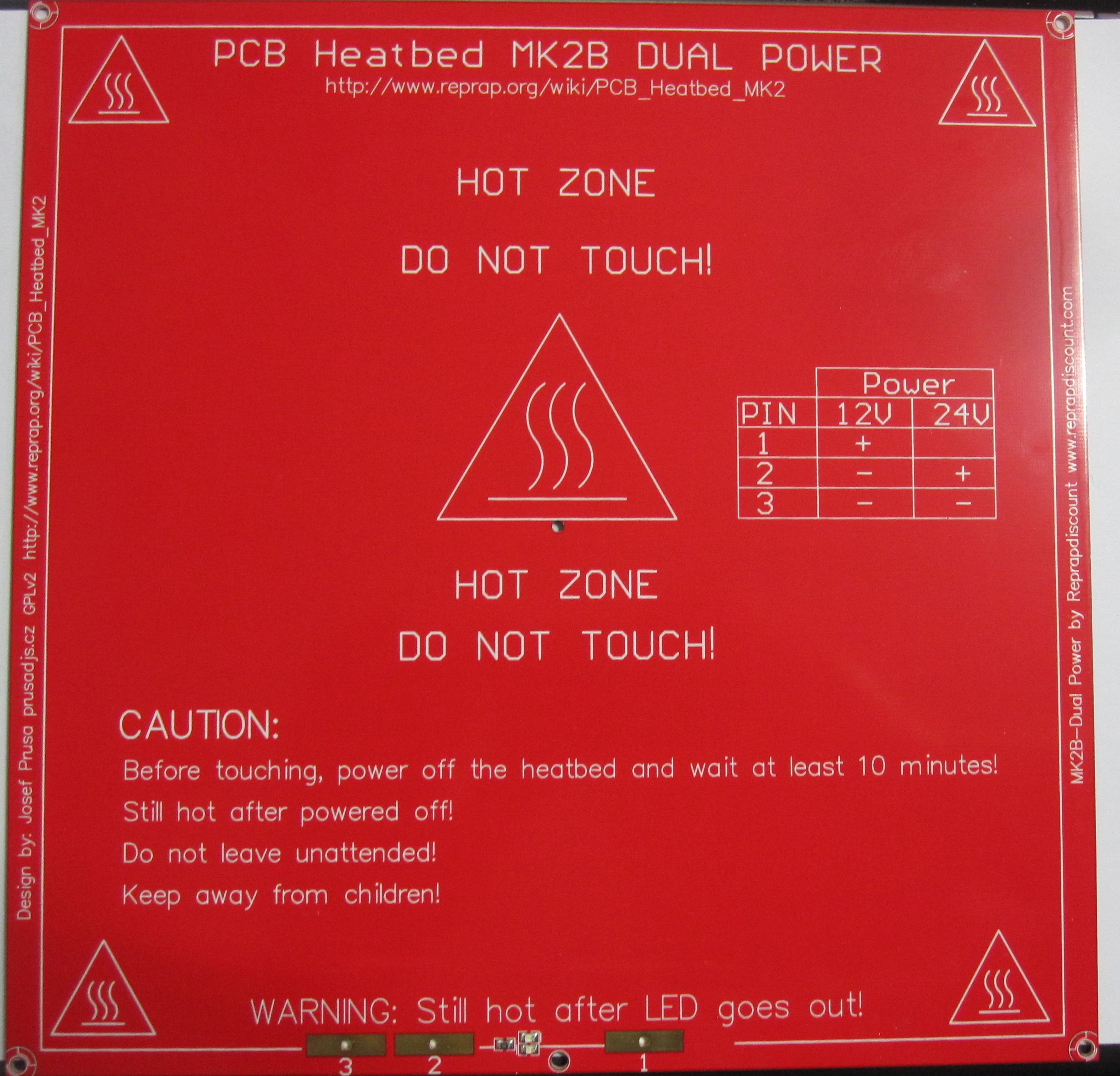
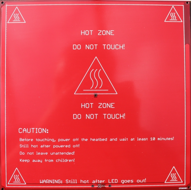
PCB Heatbead MK2b
- Dimensions 214mmx 214mm
- Laminate FR4 1.6+-0.15mm
- 2 layer, 35μm copper
- Red Soldermask – both sides
- White Silkscreen – both sides
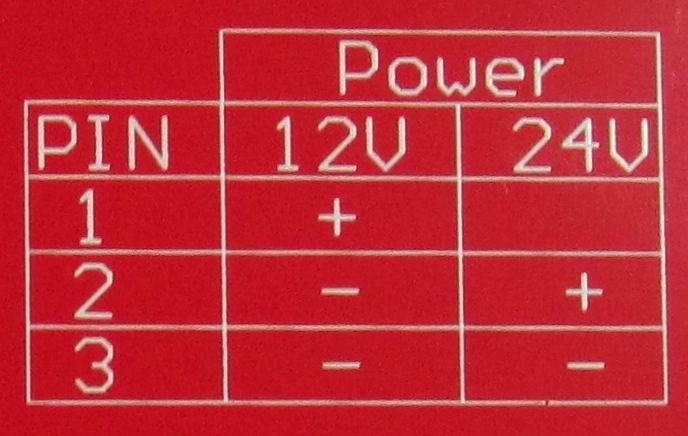
- Power Input: 12V or 24v
- copper plated holes
- resistance between 1.0-1.2 ohm (12V) or 3-3.4 ohm (24V) (Sainsmart board came in at 1.8 ohm @ 12V/3.6 ohm @ 24V)
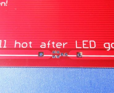
As you can see in the pictures below depending on the voltage you want to use you have to use different solder pads, but it’s written on the PCB which pads have to be used for which voltage.
Download Download PCB Heatbed MK2b – SRC @ reprapdiscount.com
Foto’s:

PCB Heatbead MK2a
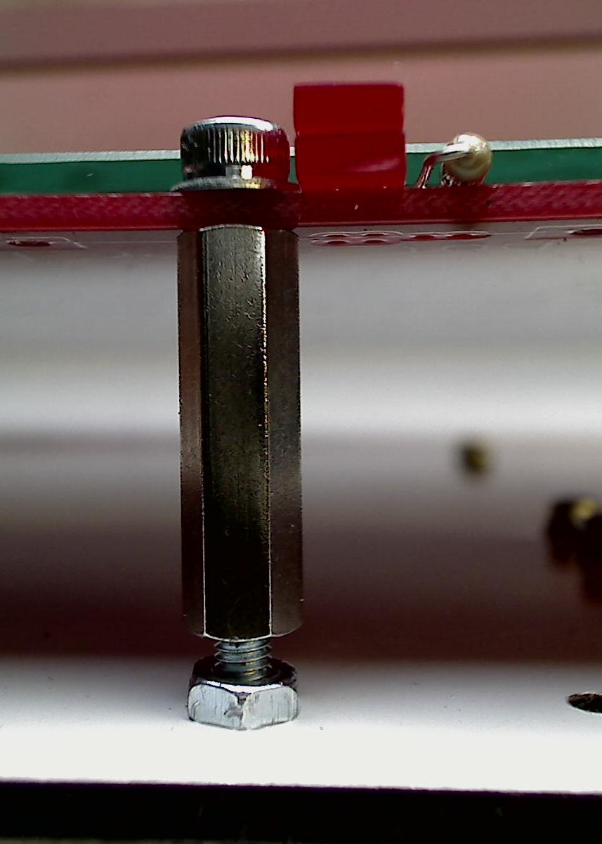
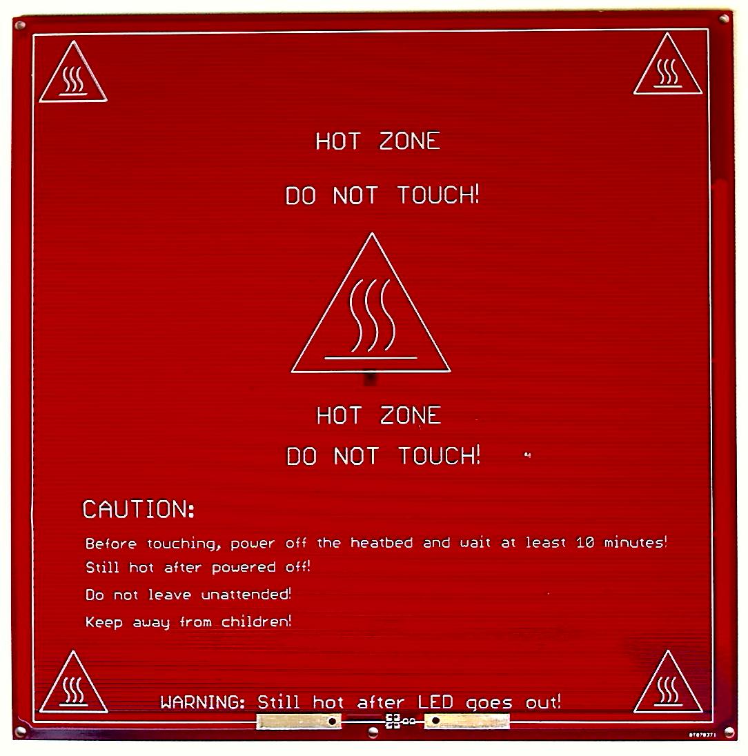
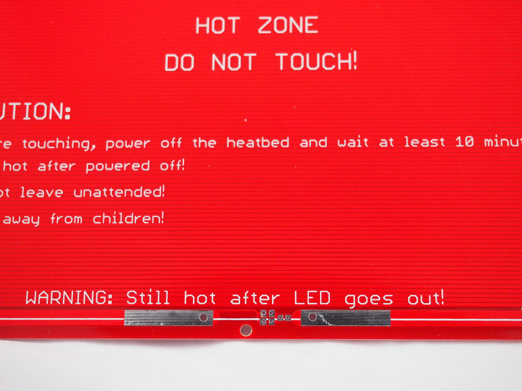
The MK2a has a central mounting hole on the front side to allow for three point mounting. This is much easier for bed leveling in comparison to 4 point mounting. First level the side with two holes and fix in place, then level the side with one hole. A glass plate is highly recommended to provide a truly flat surface and rigidity.
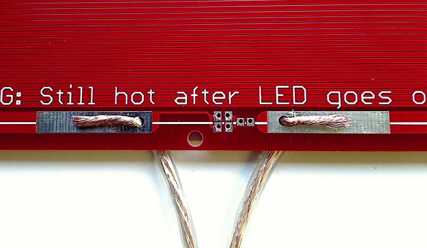
The pads to solder onto have been greatly increased as shown in the picture below. The picture shows the wires prepared for soldering routed through the holes for extra security. This does not remove the need to use proper strain relief.
Download PCB Heatbed MK2a – BRD @ reprap.org
Foto’s:
PCB Heatbead MK2
It’s not successor of MK1 even with it’s name. It’s concurrent design. – Josef Prusa
The PCB still has a side with the traces on and a side without but now the silkscreen is on both the top and bottom, this makes it look good even when ‘upside down’ under a layer of glass. The LED, resistor and power wires can be mounted on either side of the board, with either surface mount or through hole components. If you are using through hole be careful when soldering not to interfere with the glass and introduce a gap between the glass and the PCB. If the MK2 board is made properly without copper plating then be sure to only solder the LED and resistor to the same side and the tracks. This problem is solved in the MK2a by removing the pads on the non connected side.
The MK2 board can be mounted either side up and is designed to be mounted as Josef describes
1) The holes in the 4 corners to attach the heated bed MK2 to the top print plate are not suitable for M3 bolts though! Use M2.5 instead.
2) The glass protects the tracks from a head crash and is easily swapped out.
3) The board dimensions are identical to the MK1 design.
4) Insulation between the board and the thick plate should improve heat-up times and reduce energy consumption.
Polarity doesn’t affect the PCB, however the LEDs have a polarity.
The LEDs are optional, but if you choose to use the LEDs you MUST install the resistor. Solder the components to the pads on the track side of the PCB. With the MK2, conventional wired parts can be substituted for the surface mount parts. If your MK2 board is made properly without copper plating then be sure to only solder the LED and resistor to the same side and the tracks. This problem is solved in the MK2a by removing the pads on the non connected side.
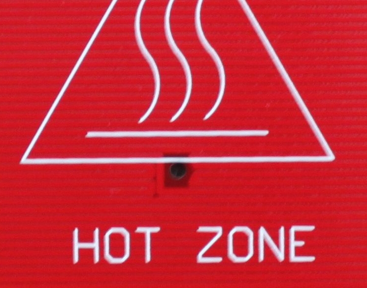
There is a central hole in the board and it is sized so a small thermistor will fit though it allowing contact directly with the glass.
todo: test efficacy of using heat sink compound to better thermally couple the thermistor to the glass
Download PCB Heatbed MK2 – BRD @ reprap.org
Foto’s:
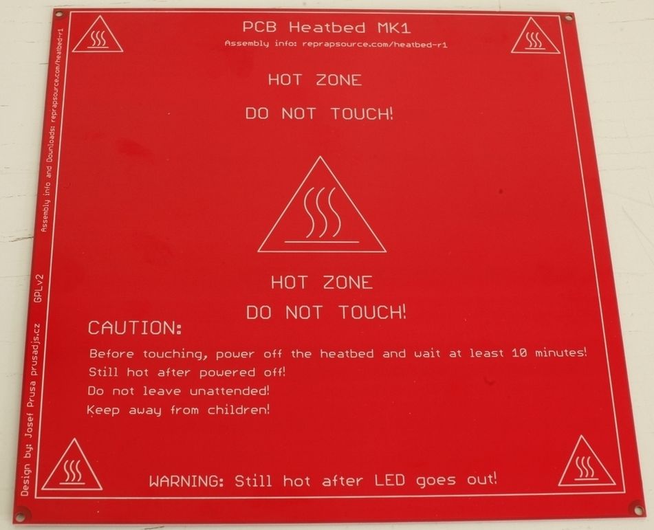
PCB Heatbead MK1
The original PCB Heatbed MK1 was developed by Josef Průša.
- 200 mm x 200 mm active heated area.
- 209 mm center-to-center mounting holes (outside the active area).
- 214 mm x 214 mm total PCB size.
Download PCB Heatbed MK1 – BRD @ thingiverse.com
Download PCB Heatbed MK1 – DXF, PDF, JPG @ thingiverse.com
Foto’s: