Apparaat – Digitale schuifmaat
Hardware
Informatie
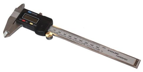
Het is mogelijk om deze digitale schuifmaten uit te lezen met een microcontroller, er is daarvoor al veel op internet te vinden kant en klare oplossingen zijn vrijwel altijd aan de dure kant, hieronder samengevat hoe je zelf een schuifmaat digitaal kan uitlezen.
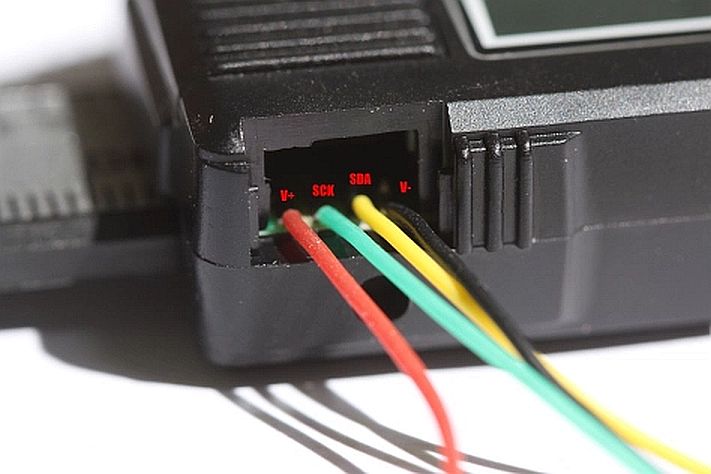
Veelal is er een klepje of schuifje (dataport) te vinden aan de bovenkant van de schuifmaat, hieronder zitten 4 spoortjes, in principe is daar een speciale stekker voor te krijgen die je daarin kan steken en klemt, maar daar is moeilijk aan te komen, je kan de draden ook solderen.
Protocollen:
- 24BIT – Two 24-bit, binary numbers are sent with the first representing the absolute position and the second representing the relative position. The two numbers are counts with a resolution of 20480 counts per inch.
- 21BIT – A single 21-bit, binary number is sent representing the absolute position. The number has a resolution of 2560 counts per inch. The 21BIT scales differ in that the DRO must provide a clock to read out the data rather than the scale providing the clock like other Chinese scale types. See the 21 bit protocol information at the ShumaTech web site for information on how to connect a 21 bit protocol scale.
- BIN6 – A single 20-bit, binary number followed by a 4-bit flag field. The 20-bit number is the count with a resolution of 2540 counts per inch when the scale is in metric mode.
- BCD7 – A single 24-bit, BCD number followed by a 4-bit flag field. The BCD number represents the seven digits shown on the scale display.
In addition, the 24BIT and BCD7 scales support a “fast” mode where they send the data to the DRO at a much higher rate than normal. The 21BIT and BIN6 scales do not support that feature.
The metal backs of Chinese scales are connected to one of the battery terminals. For 24BIT and BCD7 scales, the metal backs are connected to the positive battery terminal. For 21BIT and BIN6 scales, the scale beams are connected to the negative battery terminal. If you mix both types on one DRO, then you must insulate them to avoid shorting the DRO power supply through the machine.
Pinout
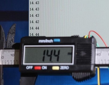
Nevertheless, it does have a data port at top of the enclosure. Before starting this project, I have searched internet about reading digital caliper and from this site, it seems clear that most of these digital caliper/scale/dial indicator output two signals — data and clock. After opening up the caliper, using a multi-meter, I quickly find out which one is V+ and which one is V- and which are data lines — voltage on data lines is about half that of V+ and this makes sense as data and clock lines are changing rapidly.
I could not deterministically figure out which line is the clock and which one is the data, but because the clock signal should be relatively stable and the pattern for data signal will change as you move the slider. So a quick experiment shows that the yellow line seems to be the data line and the cyan line is the clock. This also coincides with other findings on the internet.
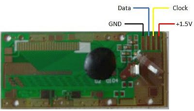
PCB:
Protocol (BIN6)
The imported digital calipers that I’ve tested so far all seem to use one pin for the clock and one pin for the data. These pins are often shared with the buttons on the front of the caliper. So, pressing a button will interfere with the data output. Yet, this also means that your project can trigger the functionality of the buttons by bringing the data or clock line low.
The imported digital calipers that I’ve tested so far all seem to use one pin for the clock and one pin for the data. These pins are often shared with the buttons on the front of the caliper. So, pressing a button will interfere with the data output. Yet, this also means that your project can trigger the functionality of the buttons by bringing the data or clock line low.
The following traces were captured using a logic analyzer. Unlike reading an official specification datasheet, this doesn’t tell us the true maximum and minimum timings; it only tells us the average timing of one example caliper. Keep that in mind by coding some slack.

Full logic analyzer trace of 24-bit digital caliper data format.
Above is one complete caliper packet when the caliper display read “0.00”. The clock pin is initially low.
The packet consists of a long start bit, a 23-bit group, a long middle bit, another 23-bit group, and then one long stop bit.
Each group is in least-significant bit order. They form a two’s compliment value of the caliper value in 10240ths of an inch. (The caliper isn’t actually this accurate — the least-significant bits oscillate quite a bit.)
Oddly, the second group has the bits inverted. For example, notice the data pin is mostly high towards the end, even though the caliper reads “0.00”.
The first 23-bit group is the absolute position since the caliper received power. The second 23-bit group is the relative position based on when the clear button was most recently pressed.
Start bit and data bit lengths of 24-bit digital caliper data format.
The start bit of the first group (A->B) is approximately 58.76 µs.
Each additional data bit is approximately 13.02 µs (B->C).
Data changes during clock high. Data seems steady when the clock is low. But, it’s probably best to read on the clock’s falling edge.
First group and middle bit lengths of 24-bit digital caliper data format.
The first data group (A->B) has 23 bits with a total period of 299.42 µs. That’s 13.018 µs per bit, which is close to the 13.02 µs measured earlier. It means the clock is relatively steady.
The start bit of the second group (B->C) is 117.2 µs.
Second group and stop bit lengths of 24-bit digital caliper data format.
23 more bits (A->B). Here is an example of the data being analyzed.
Ending (B->C) doesn’t rise up until the next packet.
Data line glitch in 24 bit digital caliper data format.
Data glitches can occur, particularly around machining equipment. Your software should be prepared to discard data that doesn’t match the expected timing for start and stop bits (or total packet length).
However, if the data pin switches state when the clock is high, that’s legal. Therefore, to be safe, data should be read on the trailing edge of the clock.
Two 24-bit groups is not the only data format output by calipers. There are many other protocols.
The read out sent out from the data port consists of 24-bit and it’s sent within 9ms.
CLOCK signal is normally high and is taken down on every bit. Thus, you need to read DATA on high-to-low transition. DATA line is taken high or low to signal corresponding bit
Data Analysis
Because the digital indicator is based on a caliper, it has the same “24-bit” format as the data protocol for other imported calipers. You should read that article for complete details. However, what follows is a specific example.
The data arrives as:
- One long bit
- 23 data bits representing absolute position since startup
- One medium-length bit
- 23 data bits representing relative position since the clear button was last pressed
- One medium-length stop bit
I only care about the second set of bits, since that matches the LCD screen. A logic analyzer (digital scope) shows the following output:
Logic analyzer trace of the second set of data in the digital indicator output
The green letter ‘M’ indicates the medium length bit. You can include this bit if you want to make the total a nice even 24 bits. Or, you can ignore this and only pay attention to 23 data bits. I’m going to focus only on the 23 data bits.
This example uses a positive value. You’ll need to put in additional work to convert negative numbers. If the most-significant bit is high, then the value is negative.
The protocol specifies that you should read the data line when the clock transitions from high to low (called “trailing edge”). The data line is allowed to change states during other times, and if you read it during high clocks, you’ll end up with wrong values from the short glitches that you should be ignoring. (There are three narrow state changes in the data line in the above image. If you follow the protocol, they won’t affect you.)
So, examining the value of the data line only when the clock line drops, you’ll get the following binary digits:
0 1 1 1 1 1 1 1 0 0 1 0 1 0 1 1 1 1 1 1 1 1 1
Invert the bits. (0 becomes 1, 1 becomes 0)
1 0 0 0 0 0 0 0 1 1 0 1 0 1 0 0 0 0 0 0 0 0 0
Reverse the order, since the device transmits the least significant bit first.
0 0 0 0 0 0 0 0 0 1 0 1 0 1 1 0 0 0 0 0 0 0 1
Convert the binary to decimal.
0b00000000010101100000001 = 0b10101100000001 = 11009
Divide that by 10240 to make it into inches. (Divide by 20480 if you decided to grab the middle bit for an even 24 bits, in which case your number is 22018.)
1.07509765625 inches
Awesome! The tool displayed 1.075 at that moment.
You may think that you can display the extra digits for improved resolution. However, the capacitive technology used in the tool is simply not that precise. The additional digits are essentially random noise. Think about it, LCDs are cheap. If there were legitimate additional digits to display, they would.
wei48221.blogspot

Bits form integer that corresponds to number of 100th of mm in case of metric system. And 2000th of inch in case of measurements in inches. That is, if display reads 3.67mm, you get integer 367. The same reading in inches is 0.1445 and this gives us 289 (0.1445 * 2000). So, in case if caliper is switched to inches, for the same reading, it will send now 289 instead of 367.
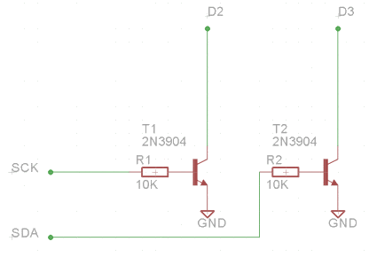
Hardware
Finding out (or guessing out) which line is which is not finished yet. The caliper uses 1.5V battery (the voltage on this caliper at moment of measure is about 1.2V, suggesting the either poor quality battery or it has been used for long time). So the signals from its data port will never exceed 1.5V and it is probably not enough for Arduino to interpret it as logic one. So level shifting is required.
Software
The hardware part are easy and straight forward. It is the communication protocol this caliper uses is the unknown part and I need to figure it out. From what I gathered on the internet, these calipers work this way: idle state where clock is low, before transmit data, the clock goes high (an UP edge), then data line is valid when clock goes low (DOWN edge), clocking out all data in this fashion and goes back to idle state.
Since I do not have any analytical tools to help me, the first thing is to confirm the yellow line is indeed the clock line. How? Because the clock signal must be very consistent, the width of each clock pulse must be consistent, unlike data line. Also the assumption that number of clock pulses is usually mutiple of 8 (8 bits or a byte), it is easy to confirm which one is the SCK line by logging duration between UP and DOWN edges and print them out. Yes, the yellow line is indeed the clock line and surprisingly, number of clocks is 24, which means 3 bytes are clocked out. This is very different from what I gathered from internet.
The second thing is to interpret data captured. It turned out, the first byte is the low byte of a 2.5 byte (20 bits) sequence, the second byte is the high byte and the first 4 bits of the third byte are highest bits of 20 bits number. The fifth bit of the third byte is the sign indicator. The number represented by the 20 bits must be divided by 200 to arrive at a reading in millimeter display. Of course, all these were guessed based setting slider at particular positions, like zero, 1 mm, etc, the patter will reveal itself.
Arduino
Hieronder het script om de schuifmaat uit te lezen (icm met een levelshifter)
|
1 2 3 4 5 6 7 8 9 10 11 12 13 14 15 16 17 18 19 20 21 22 23 24 25 26 27 28 29 30 31 32 33 34 35 36 37 38 39 40 |
int i; int sign; long value; float result; int clockpin = 11; int datapin = 12; unsigned long tempmicros; void setup() { Serial.begin(9600); pinMode(clockpin, INPUT); pinMode(datapin, INPUT); } void loop () { while (digitalRead(clockpin) == HIGH) {} //if clock is LOW wait until it turns to HIGH tempmicros=micros(); while (digitalRead(clockpin) == LOW) {} //wait for the end of the HIGH pulse if ((micros() - tempmicros) > 500) { //if the HIGH pulse was longer than 500 micros we are at the start of a new bit sequence decode(); //decode the bit sequence } } void decode() { sign=1; value=0; for (i=0;i<23;i++) { while (digitalRead(clockpin) == HIGH) { } //wait until clock returns to HIGH- the first bit is not needed while (digitalRead(clockpin) == LOW) {} //wait until clock returns to LOW if (digitalRead(datapin) == LOW) { if (i<20) { value|= 1<<i; } if (i==20) { sign=-1; } } } result = (value * sign) / 100.00; Serial.println(result, 2); //print result with 2 decimals delay(200); } |
Output:
|
1 2 3 4 5 6 7 8 9 10 11 12 13 14 15 16 17 18 19 20 |
0.00 0.00 0.00 -0.12 -0.12 -0.12 -0.18 -2.43 -4.01 -4.01 -3.49 6.69 9.51 10.28 10.30 10.29 9.47 6.55 2.94 2.63 |
Het script hieronder laat de bitreeks zien met enen en nullen:
|
1 2 3 4 5 6 7 8 9 10 11 12 13 14 15 16 17 18 19 20 21 22 23 24 25 26 27 28 29 30 31 32 33 |
// Pin Declarations int dataIn = 12; int clockIn = 11; // Variables int clock = 1; int lastClock = 1; unsigned long time = 0; unsigned long timeStart = 0; int out = 0; void setup() { // Pin Set Up pinMode(dataIn, INPUT); pinMode(clockIn, INPUT); Serial.begin(9600); Serial.println("Ready: "); } void loop(){ lastClock = clock; clock = digitalRead(clockIn); if (lastClock == 1 && clock == 0){ out = digitalRead(dataIn)+digitalRead(dataIn)+digitalRead(dataIn); // Tripple sampling to remove glitches if((micros() - time) > 800){ Serial.println(" "); } else if((micros() - time) > 400){ Serial.print(" "); } if (out > 1){ Serial.print("1"); } else{ Serial.print("0"); } Serial.print(","); time = micros(); } } |
Output:
|
1 2 3 4 5 6 7 8 9 10 11 12 13 14 15 16 17 18 19 20 21 22 23 24 25 26 27 28 29 30 31 32 33 34 35 36 37 38 39 40 41 42 43 44 45 46 47 48 49 50 51 |
1,1,1,1, 1,1,1,1, 1,1,1,1, 1,1,1,1, 1,1,1,1, 1,1,1,1, 1,1,1,1, 1,1,1,1, 1,1,1,1, 1,1,1,1, 1,1,1,1, 1,1,1,1, 1,1,1,1, 1,1,1,1, 1,1,1,1, 1,1,1,1, 1,1,1,1, 1,1,1,1, 0,1,1,1, 0,0,1,1, 1,1,1,1, 1,1,1,1, 1,1,1,1, 0,1,1,1, 1,0,0,1, 0,0,0,1, 1,1,1,1, 1,1,1,1, 1,1,1,1, 0,1,1,1, 0,0,1,0, 0,0,0,0, 1,1,1,1, 1,1,1,1, 1,1,1,1, 0,1,1,1, 0,0,0,0, 0,0,1,1, 0,1,1,1, 1,1,1,1, 1,1,1,1, 0,1,1,1, 0,0,0,0, 0,0,0,1, 0,1,1,1, 1,1,1,1, 1,1,1,1, 0,1,1,1, 0,1,1,1, 1,1,0,0, 0,1,1,1, 1,1,1,1, 1,1,1,1, 0,1,1,1, 1,1,0,1, 0,0,1,1, 1,0,1,1, 1,1,1,1, 1,1,1,1, 0,1,1,1, 0,0,0,0, 0,1,1,0, 1,0,1,1, 1,1,1,1, 1,1,1,1, 0,1,1,1, 0,1,1,1, 1,1,0,0, 1,0,1,1, 1,1,1,1, 1,1,1,1, 0,1,1,1, 0,1,0,0, 0,0,1,0, 0,0,1,1, 1,1,1,1, 1,1,1,1, 0,1,1,1, 0,1,0,0, 0,0,1,0, 0,0,1,1, 1,1,1,1, 1,1,1,1, 0,1,1,1, 0,1,0,0, 0,0,1,0, 0,0,1,1, 1,1,1,1, 1,1,1,1, 0,1,1,1, 1,0,0,0, 0,0,1,0, 0,0,1,1, 1,1,1,1, 1,1,1,1, 0,1,1,1, 1,0,0,0, 0,0,1,0, 0,0,1,1, 1,1,1,1, 1,1,1,1, 0,1,1,1, 0,1,1,0, 0,0,1,0, 0,0,1,1, 1,1,1,1, 1,1,1,1, 0,1,1,1, 1,1,0,1, 1,1,1,0, 0,0,1,1, 1,1,1,1, 1,1,1,1, 0,1,1,1, 0,1,0,1, 1,1,1,1, 0,0,1,1, 1,1,1,1, 1,1,1,1, 0,1,1,1, 0,1,1,0, 0,0,1,0, 1,0,1,1, 1,1,1,1, 1,1,1,1, 0,1,1,1, 0,0,1,0, 0,1,0,1, 1,0,1,1, 1,1,1,1, 1,1,1,1, 0,1,1,1, 1,0,1,1, 0,1,1,0, 0,1,1,1, 1,1,1,1, 1,1,1,1, 0,1,1,1, 0,0,1,0, 1,1,1,1, 0,1,1,1, 1,1,1,1, 1,1,1,1, 0,1,1,1, 1,0,0,1, 1,0,1,0, 1,1,1,1, 1,1,1,1, 1,1,1,1, 0,1,1,1, 1,1,1,1, 0,1,1,1, 1,1,1,1, 1,1,1,1, 1,1,1,1, 0,1,1,1, 1,0,0,0, 0,0,1,0, 1,1,1,1, 1,1,1,1, 1,1,1,1, 1,1,1,1, 0,0,1,0, 1,1,1,1, 0,1,1,1, 1,1,1,1, 1,1,1,1, 1,1,1,1, 1,0,0,0, 0,0,1,1, 0,1,1,1, 1,1,1,1, 1,1,1,1, 1,1,1,1, 1,0,1,0, 1,1,0,1, 0,1,1,1, 1,1,1,1, 1,1,1,1, 1,1,1,1, 1,0,1,0, 1,1,0,1, 0,1,1,1, 1,1,1,1, 1,1,1,1, 1,1,1,1, 1,0,1,0, 1,1,0,1, 0,1,1,1, 1,1,1,1, 1,1,1,1, 1,1,1,1, 1,0,1,0, 1,1,0,1, 0,1,1,1, 1,1,1,1, 1,1,1,1, 1,1,1,1, 1,0,0,1, 1,1,0,1, 0,1,1,1, 1,1,1,1, 1,1,1,1, 1,1,1,1, 1,1,0,1, 1,1,0,1, 0,1,1,1, 1,1,1,1, 1,1,1,1, 1,1,1,1, 0,0,0,1, 0,0,0,1, 1,1,1,1, 1,1,1,1, 1,1,1,1, 1,1,1,1, 0,0,1,1, 0,0,1,0, 0,1,1,1, 1,1,1,1, 1,1,1,1, 0,1,1,1, 1,0,1,1, 1,0,1,0, 1,0,1,1, 1,1,1,1, 1,1,1,1, 0,1,1,1, 0,0,0,0, 1,1,0,1, 0,0,1,1, 1,1,1,1, 1,1,1,1, 0,1,1,1, 0,1,0,0, 0,1,0,0, 0,0,1,1, 1,1,1,1, 1,1,1,1, 0,1,1,1, 0,1,1,1, 0,0,0,0, 0,0,1,1, 1,1,1,1, 1,1,1,1, 0,1,1,1, 0,1,1,1, 0,0,0,0, 0,0,1,1, 1,1,1,1, 1,1,1,1, 0,1,1,1, 0,1,1,1, 1,1,1,0, 0,0,1,1, 1,1,1,1, 1,1,1,1, 0,1,1,1, 1,0,1,0, 1,0,1,1, 1,0,1,1, 1,1,1,1, 1,1,1,1, 0,1,1,1, 0,0,1,1, 0,0,0,1, 0,1,1,1, 1,1,1,1, 1,1,1,1, 0,1,1,1, 1,0,0,1, 1,1,0,0, 1,1,1,1, 1,1,1,1, 1,1,1,1, 0,1,1,1, 1,0,1,0, 1,0,1,1, 1,1,1,1, 1,1,1,1, 1,1,1,1, 0,1,1,1, 1,1,0,0, 1,0,1,0, 1,1,1,1, 1,1,1,1, 1,1,1,1, 1,1,1,1, 1,1,1,1, 0,1,0,1, 0,1,1,1, 1,1,1,1, 1,1,1,1, 1,1,1,1, 0,0,1,1, 1,1,0,0, 0,1,1,1, 1,1,1,1, 1,1,1,1, 1,1,1,1, 0,1,1,1, 0,1,1,1, 1,0,1,1, 1,1,1,1, 1,1,1,1, 1,1,1,1, |
Of nog simpeler:
|
1 2 3 4 5 6 7 8 9 10 11 12 13 14 15 16 17 18 19 20 21 22 23 24 |
const byte clockPin = 3; const byte dataPin = 2; int j = 0, k = 0; int myData[24]; // the clock signal represents 6 sets times 4 pulses; see the picture void setup() { pinMode(clockPin, INPUT_PULLUP); pinMode(dataPin, INPUT_PULLUP); Serial.begin(9600); attachInterrupt(digitalPinToInterrupt(clockPin), myISR, RISING); } void loop() { if (j >= 24) { j = 0; for (k = 23; k >= 0; k--) Serial.print(myData[k]); Serial.println(""); }//if } void myISR() { myData[j] = digitalRead(dataPin); j++; } |
Output:
|
1 2 3 4 5 6 7 8 9 10 11 12 13 14 15 16 17 18 19 20 21 22 23 |
011011111111111110111001 011011111111111110111001 011011111111111110111001 011011111111111110111001 011011111111111110111001 011011111111111110111001 011011111111111110111001 011011111111111110111000 011011111111111111011001 011111111111111100111110 011111111111111010111001 011111111111111010010011 011111111111111001011100 011111111111111000011001 011111111111110111000110 011111111111110110000010 011111111111110101110000 011111111111110101101000 011111111111110101101000 011111111111110101101000 011111111111110101101000 011111111111110101101000 011111111111110101101000 |
Bronnen:
pylin.com
robotroom.com
wei48221.blogspot.com
pcbheaven.com
shumatech.com