Arduino – CAN Bus communicatie
Het is mogelijk een arduino te gebruiken met een CAN Bus interface, met CAN Bus kan je datalijnen gebruiken tot ca. 500m, en apparaten werken peer-to-peer (ipv master – slave) dat is erg interessant!
Wat je nodig hebt is een CAN Bus module met een controller en transciever om het differentiële signaal van de CAN Bus bus om te zetten naar SPI signalen voor de Arduino (en andersom).
Hardware CAN Bus controller module
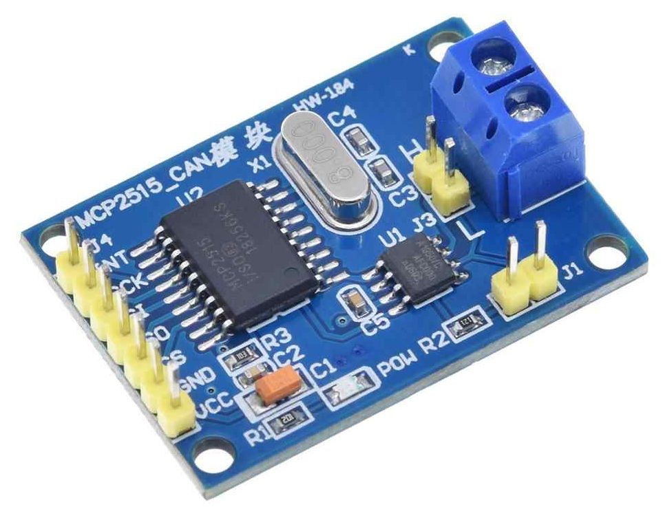
The MCP2515 CAN Bus Controller is a simple Module that supports CAN Protocol version 2.0B and can be used for communication at 1Mbps. In order to setup a complete communication system, you will need two CAN Bus Module.
- Supports CAN V2.0B specification, with communication speed up to 1Mb/s.
- 0 to 8-byte data field with standard frame, extended frame and remote frame.
- 5V DC power supply module, SPI interface protocol control.
- Onboard 120 Ohm termination resistor.
- Working current: 5mA (1 microamp standby current).
- Operating temperature: -40 C – +85 C
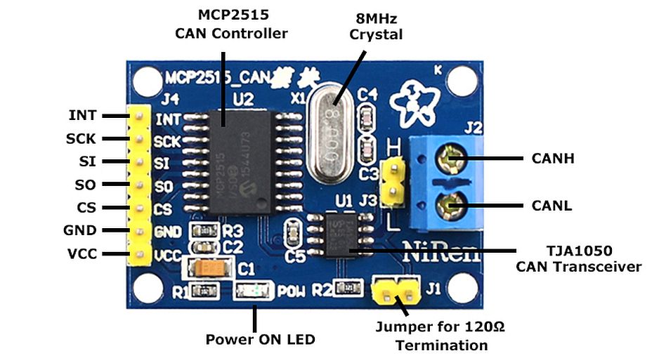
This particular module is based on MCP2515 CAN Controller IC and TJA1050 CAN Transceiver IC. The MCP2515 IC is a standalone CAN Controller and has integrated SPI Interface for communication with microcontrollers.
Coming to the TJA1050 IC, it acts as an interface between the MCP2515 CAN Controller IC and the Physical CAN Bus.
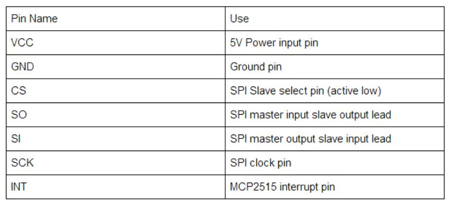
The following image shows the components and pins on a typical MCP2515 Module:
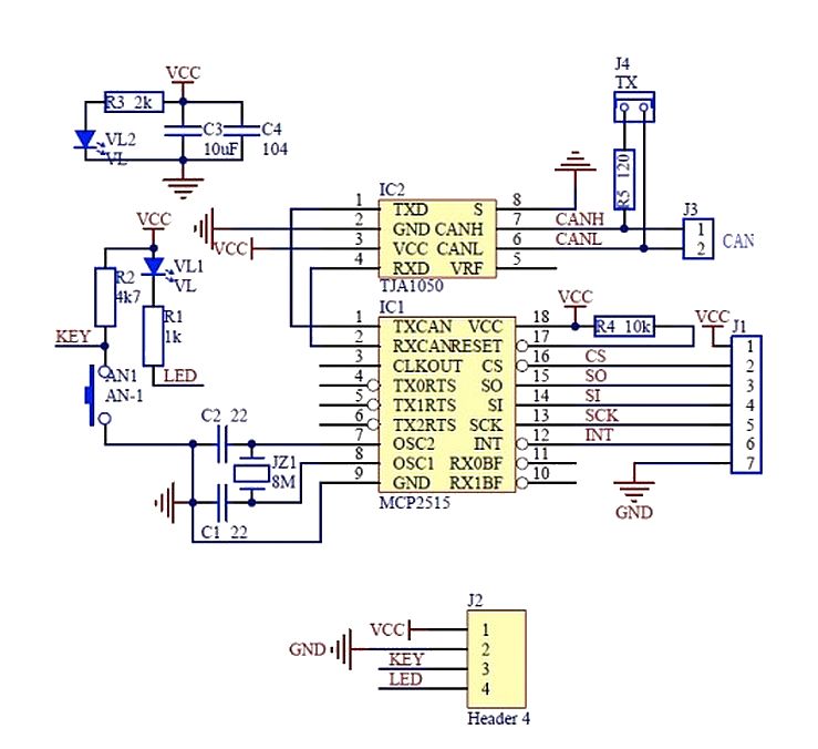
Module schema
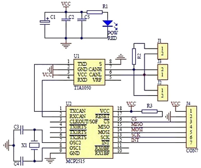
Before seeing the schematic of the module, you need to understand a couple of things about both the ICs i.e. MCP2515 and TJA1050.
MCP2515 IC is the main controller that internally consists of three main subcomponents: The CAN Module, the Control Logic and the SPI Block.
CAN Module is responsible for transmitting and receiving messages on the CAN Bus. Control Logic handles the setup and operation of the MCP2515 by interfacing all the blocks. The SPI Block is responsible for the SPI Communication interface.
Coming to the TJA1050 IC, since it acts as an interface between MCP2515 CAN Controller and the physical CAN Bus, this IC is responsible for taking the data from the controller and relaying it on to the bus.
The following image shows the schematic of the MCP2515 CAN Module and it shows how MCP2515 IC and TJA1050 IC are connected on the Module.
Schema met component waarden:
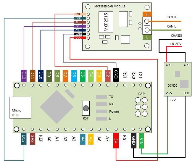
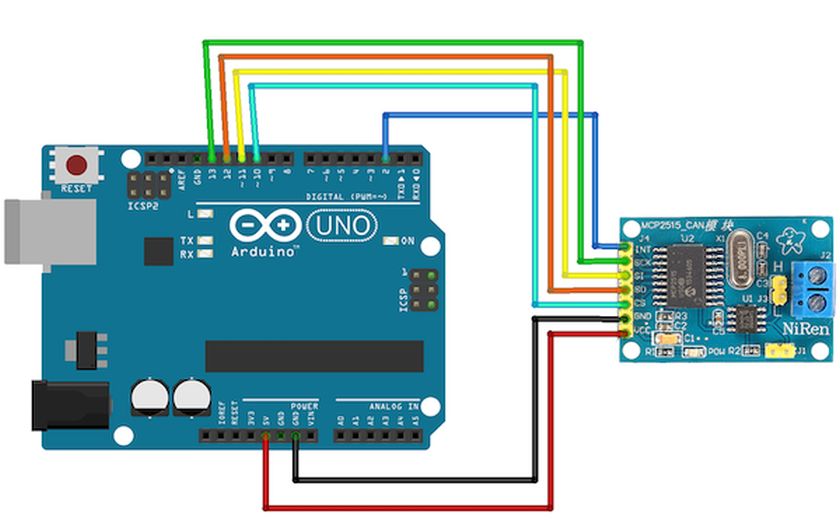
Arduino schema
Sluit de CAN Bus Module aan zoals hieronder aangegeven.
Arduino NANO:
Arduino UNO:
In duale opstelling UNO:
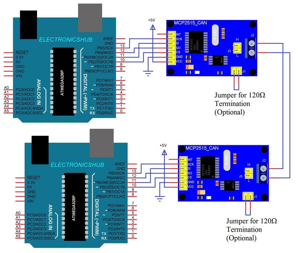
In duale opstelling NANO:
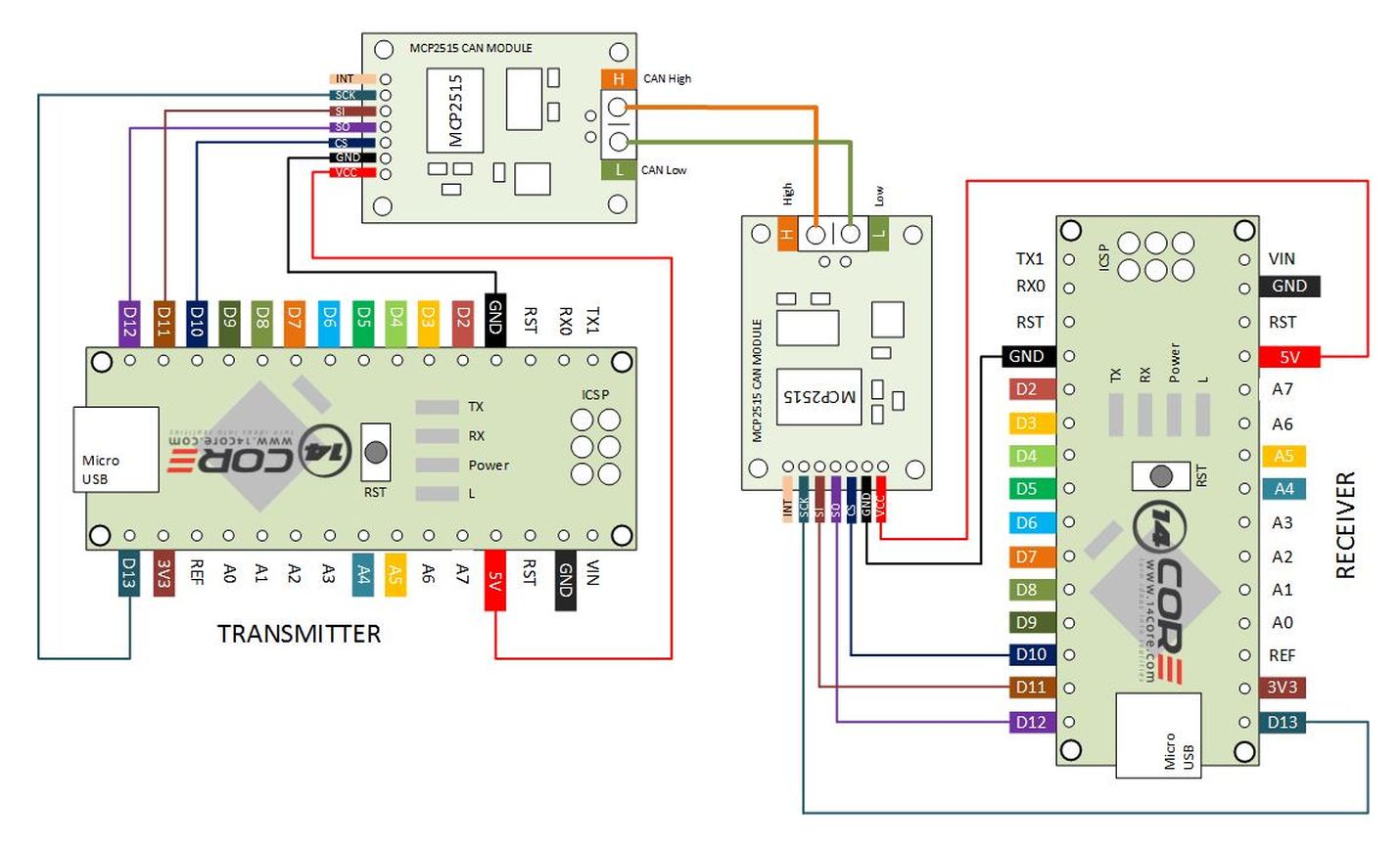
For Transmitter (Arduino 1)
MCP2515 Module -> Arduino Nano
MPC2515 – VCC -> +5V
MPC2515 – GND -> GND
MPC2515 – CS -> D10 (SPI_SS)
MPC2515 – SO -> D12 (SPI_MISO)
MPC2515 – S I -> D11 (SPI_MOSI)
MPC2515 – SCK -> D13 (SPI_SCK)
MPC2515 – INT -> D2
For Receiver (Arduino 2)
MCP2515 Module -> Arduino Uno
VCC -> +5V
GND -> GND
CS -> 10 (SPI_SS)
SO -> 12 (SPI_MISO)
SI -> 11 (SPI_MOSI)
SCK -> 13 (SPI_SCK)
INT -> 2
Between two MCP2515
MCP2515 on Arduino Nano (Arduino 1) -> MCP2515 on Arduino Nano (Arduino 2)
H -> H
L -> L
Scripts
Wat heb je nodig?
1) Arduino CAN Bus bibliotheek (autowp): https://github.com/autowp/arduino-mcp2515
arduino-mcp2515-master (DL @ 2020-12-08)
Transmitter script
|
1 2 3 4 5 6 7 8 9 10 11 12 13 14 15 16 17 18 19 20 21 22 23 24 25 26 27 |
#include <SPI.h> // Library for using SPI Communication #include <mcp2515.h> // Library for using CAN Communication struct can_frame canMsg; MCP2515 mcp2515(10); void setup(){ SPI.begin(); // Begins SPI communication mcp2515.reset(); mcp2515.setBitrate(CAN_500KBPS, MCP_8MHZ); // Sets CAN at speed 500KBPS and Clock 8MHz mcp2515.setNormalMode(); } void loop(){ canMsg.can_id = 0x036; // CAN id as 0x036 canMsg.can_dlc = 8; // CAN data length as 8 canMsg.data[0] = 125; // value in [0] (max=255) canMsg.data[1] = 203; // value in [1] (max=255) canMsg.data[2] = 255; // value in [2] (max=255) canMsg.data[3] = 0x00; // Rest all with 0 canMsg.data[4] = 0x00; canMsg.data[5] = 0x00; canMsg.data[6] = 0x00; canMsg.data[7] = 0x00; mcp2515.sendMessage(&canMsg); //Sends the CAN message delay(1000); } |
Reciever script
|
1 2 3 4 5 6 7 8 9 10 11 12 13 14 15 16 17 18 19 20 21 |
#include <SPI.h> // Library for using SPI Communication #include <mcp2515.h> // Library for using CAN Communication struct can_frame canMsg; MCP2515 mcp2515(10); // SPI CS Pin 10 void setup() { SPI.begin(); // Begins SPI communication Serial.begin(9600); // Begins Serial Communication at 9600 baud rate mcp2515.reset(); mcp2515.setBitrate(CAN_500KBPS, MCP_8MHZ); // Sets CAN at speed 500KBPS and Clock 8MHz mcp2515.setNormalMode(); // Sets CAN at normal mode } void loop(){ if ((mcp2515.readMessage(&canMsg) == MCP2515::ERROR_OK) && (canMsg.can_id == 0x036)){ Serial.print("Getal 1: "); Serial.print(canMsg.data[0]); Serial.print(", Getal 2: "); Serial.print(canMsg.data[1]); Serial.print(", Getal 3: "); Serial.println(canMsg.data[2]); } } |
Console uitput van de ontvanger:
|
1 2 3 4 |
Getal 1: 125, Getal 2: 203, Getal 3: 255 Getal 1: 125, Getal 2: 203, Getal 3: 255 Getal 1: 125, Getal 2: 203, Getal 3: 255 Getal 1: 125, Getal 2: 203, Getal 3: 255 |
Met 3 apparaten
Transmitter script 1
|
1 2 3 4 5 6 7 8 9 10 11 12 13 14 15 16 17 18 19 20 21 22 23 24 25 26 27 |
#include <SPI.h> // Library for using SPI Communication #include <mcp2515.h> // Library for using CAN Communication struct can_frame canMsg; MCP2515 mcp2515(10); void setup(){ SPI.begin(); // Begins SPI communication mcp2515.reset(); mcp2515.setBitrate(CAN_500KBPS, MCP_8MHZ); // Sets CAN at speed 500KBPS and Clock 8MHz mcp2515.setNormalMode(); } void loop(){ canMsg.can_id = 0x036; // CAN id as 0x036 canMsg.can_dlc = 8; // CAN data length as 8 canMsg.data[0] = 125; // value in [0] (max=255) canMsg.data[1] = 203; // value in [1] (max=255) canMsg.data[2] = 255; // value in [2] (max=255) canMsg.data[3] = 0x00; // Rest all with 0 canMsg.data[4] = 0x00; canMsg.data[5] = 0x00; canMsg.data[6] = 0x00; canMsg.data[7] = 0x00; mcp2515.sendMessage(&canMsg); //Sends the CAN message delay(1000); } |
Transmitter script 2
|
1 2 3 4 5 6 7 8 9 10 11 12 13 14 15 16 17 18 19 20 21 22 23 24 25 26 27 |
#include <SPI.h> // Library for using SPI Communication #include <mcp2515.h> // Library for using CAN Communication struct can_frame canMsg; MCP2515 mcp2515(10); void setup(){ SPI.begin(); // Begins SPI communication mcp2515.reset(); mcp2515.setBitrate(CAN_500KBPS, MCP_8MHZ); // Sets CAN at speed 500KBPS and Clock 8MHz mcp2515.setNormalMode(); } void loop(){ canMsg.can_id = 0x021; // CAN id as 0x036 canMsg.can_dlc = 8; // CAN data length as 8 canMsg.data[0] = 100; // value in [0] (max=255) canMsg.data[1] = 111; // value in [1] (max=255) canMsg.data[2] = 222; // value in [2] (max=255) canMsg.data[3] = 0x00; // Rest all with 0 canMsg.data[4] = 0x00; canMsg.data[5] = 0x00; canMsg.data[6] = 0x00; canMsg.data[7] = 0x00; mcp2515.sendMessage(&canMsg); //Sends the CAN message delay(400); } |
Reciever script
|
1 2 3 4 5 6 7 8 9 10 11 12 13 14 15 16 17 18 19 20 21 22 23 24 25 26 27 28 |
#include <SPI.h> // Library for using SPI Communication #include <mcp2515.h> // Library for using CAN Communication struct can_frame canMsg; MCP2515 mcp2515(10); // SPI CS Pin 10 void setup() { SPI.begin(); // Begins SPI communication Serial.begin(9600); // Begins Serial Communication at 9600 baud rate mcp2515.reset(); mcp2515.setBitrate(CAN_500KBPS, MCP_8MHZ); // Sets CAN at speed 500KBPS and Clock 8MHz mcp2515.setNormalMode(); // Sets CAN at normal mode } void loop(){ if (mcp2515.readMessage(&canMsg) == MCP2515::ERROR_OK) { if (canMsg.can_id == 0x036) { Serial.print("0x036 - Getal 1: "); Serial.print(canMsg.data[0]); Serial.print(", Getal 2: "); Serial.print(canMsg.data[1]); Serial.print(", Getal 3: "); Serial.println(canMsg.data[2]); } if (canMsg.can_id == 0x021) { Serial.print("0x021 - Getal 1: "); Serial.print(canMsg.data[0]); Serial.print(", Getal 2: "); Serial.print(canMsg.data[1]); Serial.print(", Getal 3: "); Serial.println(canMsg.data[2]); } } } |
Console uitput van de ontvanger:
|
1 2 3 4 5 6 7 8 9 10 11 12 13 |
0x021 - Getal 1: 100, Getal 2: 111, Getal 3: 222 0x021 - Getal 1: 100, Getal 2: 111, Getal 3: 222 0x021 - Getal 1: 100, Getal 2: 111, Getal 3: 222 0x036 - Getal 1: 125, Getal 2: 203, Getal 3: 255 0x021 - Getal 1: 100, Getal 2: 111, Getal 3: 222 0x021 - Getal 1: 100, Getal 2: 111, Getal 3: 222 0x036 - Getal 1: 125, Getal 2: 203, Getal 3: 255 0x021 - Getal 1: 100, Getal 2: 111, Getal 3: 222 0x021 - Getal 1: 100, Getal 2: 111, Getal 3: 222 0x021 - Getal 1: 100, Getal 2: 111, Getal 3: 222 0x036 - Getal 1: 125, Getal 2: 203, Getal 3: 255 0x021 - Getal 1: 100, Getal 2: 111, Getal 3: 222 0x021 - Getal 1: 100, Getal 2: 111, Getal 3: 222 |
Bronnen:
https://www.electronicshub.org/arduino-mcp2515-can-bus-tutorial/
https://copperhilltech.com/mcp2515-can-bus-breakout-board-with-spi-interface/