Arduino Library – Encoder
![]()
Installatie van Arduino IDE libraries: Arduino info
Informatie (ENG):

Description
Encoder counts pulses from quadrature encoded signals, which are commonly available from rotary knobs, motor or shaft sensors and other position sensors.
Encoder provides 4X counting mode and highly optimized code.
Encoders have 2 signals, which must be connected to 2 pins. There are three options.
- Best Performance: Both signals connect to interrupt pins.
- Good Performance: First signal connects to an interrupt pin, second to a non-interrupt pin.
- Low Performance: Both signals connect to non-interrupt pins
| Board | Interrupt Pins |
LED Pin (do not use) |
|---|---|---|
| Teensy 3.0 | All Digital Pins | 13 |
| Teensy 2.0 | 5, 6, 7, 8 | 11 |
| Teensy 1.0 | 0, 1, 2, 3, 4, 6, 7, 16 | |
| Teensy++ 2.0 | 0, 1, 2, 3, 18, 19, 36, 37 | 6 |
| Teensy++ 1.0 | 0, 1, 2, 3, 18, 19, 36, 37 | |
| Arduino Due | All Digital Pins | 13 |
| Arduino Uno | 2, 3 | 13 |
| Arduino Leonardo | 0, 1, 2, 3 | 13 |
| Arduino Mega | 2, 3, 18, 19, 20, 21 | 13 |
| Sanguino | 2, 10, 11 | 0 |
Low cost encoders only connect their pins to ground. Encoder will activate the on-chip pullup resistors. If you connect lengthy wires, adding 1K pullup resistors may provide a better signal.
Basic Usage
Encoder myEnc(pin1, pin2);
Create an Encoder object, using 2 pins. You may create mulitple Encoder objects, where each uses its own 2 pins. The first pin should be capable of interrupts. If both pins have interrupt capability, both will be used for best performance. Encoder will also work in low performance polling mode if neither pin has interrupts.
myEnc.read();
Returns the accumulated position. This number can be positive or negative.
myEnc.write(newPosition);
Set the accumulated position to a new number.
Understanding Quadrature Encoded Signals
Encoders can sense movement in either direction, by detecting holes or marks as they move past 2 positions. When the blue disc in the diagram below spins clockwise, the changes are first detected by pin 1, and then by pin 2. When it spins counterclockwise, pin 2 is first to detect changes. This scheme is called “quadrature encoding” because the waveforms detected by the 2 pins are 90 degrees out of phase.
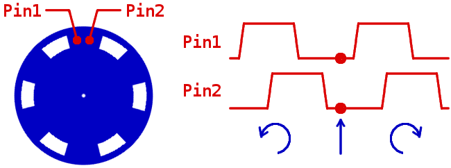
The Encoder library monitors the 2 pins and updates a count of the relative change in position. The library updates its count at each change, which is often called 4X counting, since 4 counts are available for each physical mark or hole in the encoder hardware.
Interrupt Latency Requirements
Encoder requires low latency response to changes of the signals. Using either the first or both pins with interrupts works very well. However, if interrupts are disabled for lengthy times, either by your code or another library, Encoder may miss a change. The result is incorrect counting. The next 1, 2 or 3 changes may produce wrong results.
SoftwareSerial and NewSoftSerial are very likely to cause problems.
Optimized Interrupt Option
When used on Teensy and Arduino, Encoder uses very optimized interrupt routines written in assembly language. Normally, Encoder usesattachInterrupt(), which allows dynamically attaching functions to each interrupt. The dynamic function call adds slight overhead. To eliminate this extra overhead, you can use this option.
|
1 2 3 4 |
// This optional setting causes Encoder to use more optimized code, // It must be defined before Encoder.h is included. #define ENCODER_OPTIMIZE_INTERRUPTS #include <Encoder.h> |
Encoder will directly define interrupts the minimum overhead. The downside is a conflict if any other code in your sketch or any libraries you use require attachInterrupt().
Maximum Speed and CPU Usage
SpeedTest example, in File > Examples > Encoder > SpeedTest, provides a simple way to verify how much CPU time Encoder is consuming. The following SpeedTest results have been measured:
| Board | Maximum Interrupt Rate (approximate) |
Conditions |
|---|---|---|
| Teensy 2.0 | 100 kHz | Normal |
| Teensy 2.0 | 127 kHz | ENCODER_OPTIMIZE_INTERRUPTS |