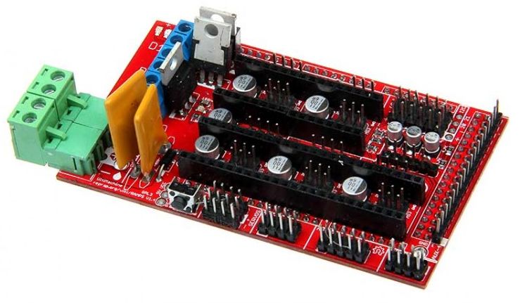
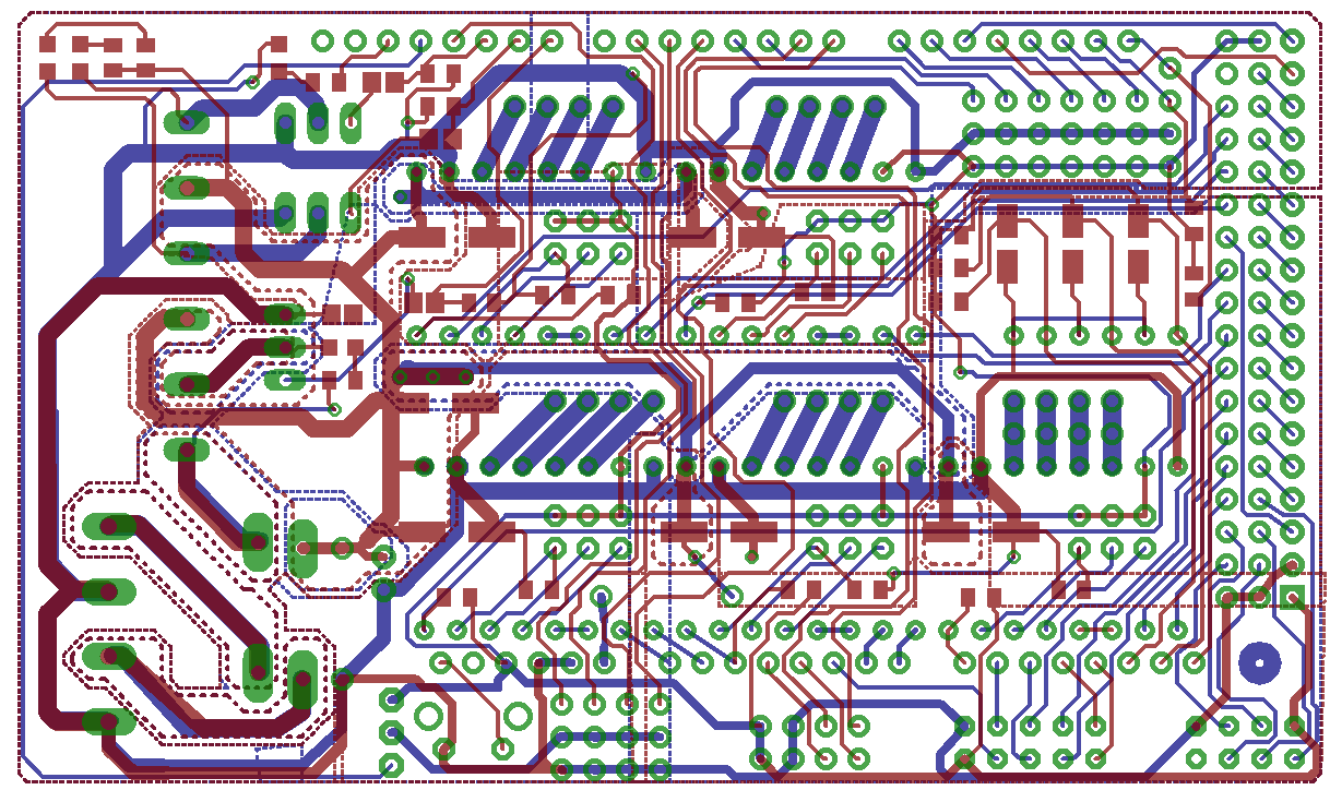
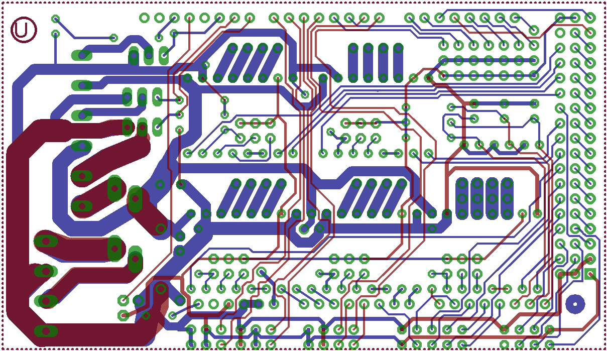
Arduino MEGA Shield – RAMPS
![]()
Informatie (ENG):
RepRap Arduino Mega Pololu Shield, or RAMPS for short. It is designed to fit the entire electronics needed for a RepRap in one small package for low cost. RAMPS interfaces an Arduino Mega with the powerful Arduino MEGA platform and has plenty room for expansion. The modular design includes plug in stepper drivers and extruder control electronics on an Arduino MEGA shield for easy service, part replacement, upgrade-ability and expansion. Additionally, a number of Arduino expansion boards can be added to the system as long as the main RAMPS board is kept to the top of the stack.
Introduction
Version 1.4 uses surface mount capacitors and resistors to further cover edge issue cases. As of version 1.3 in order to fit more stuff RAMPS is no longer designed for easy circuit home etching. If you want to etch your own PCB either get version 1.25 or Generation 7 Electronics. Version 1.25 and earlier are “1.5 layer” designed boards (i.e. it’s double sided board, but one of layers can easily be replaced with wire-jumpers) that is printable on your RepRap with the etch resist pen method, or home fabbed with toner transfer.
This board is mostly based on Adrian’s Pololu_Electronics and work by Tonok. Copper etch resists methods suggested by Vik. Also inspired by Vik’s work with EasyDrivers. Circuit design based mostly on Adrian’s Pololu_Electronics. Joaz at RepRapSource.com supplied initial pin definitions and many design improvements. Much inspiration, suggestions, and ideas from Prusajr, Kliment, Maxbots, Rick, and many others in the RepRap community.
Features
- It has provisions for the cartesian robot and extruder.
- Expandable to control other accessories.
- 3 mosfets for heater / fan outputs and 3 thermistor circuits.
- Fused at 5A for additional safety and component protection
- Heated bed control with additional 11A fuse
- Fits 5 Pololu stepper driver board
- Pololu boards are on pin header sockets so they can be replaced easily or removed for use in future designs.
- I2C and SPI pins left available for future expansion.
- All the Mosfets are hooked into PWM pins for versatility.
- Servo style connectors are used to connect to the endstops, motors, and leds. These connectors are gold plated, rated for 3A, very compact, and globally available.
- USB type B receptacle
- SD Card add on available — Available now made by Kliment – Sdramps
- LEDs indicate when heater outputs on
- Option to connect 2 motors to Z for Prusa Mendel
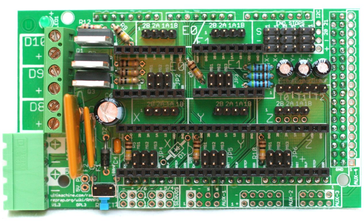
RAMPS v1.4

RAMPS v1.3
RAMPS v1.2


Firmware and Pin Assignments
RAMPS 1.4 uses the same pin definitions as 1.3.
You will need the Arduino software to upload the firmware to Arduino Mega. The version of Arduino you need may be determined by the firmware you want to use. The current (as of 2014-01-22) Marlin firmware is compatible with Arduino version 1.0.5. Some other firmwares may require Arduino software version 0023, NOT the most recent version. Please see your firmware documentations if you need assistance.
Troubleshooting: You may need to make sure that the driver is installed for the Arduino MEGA by going to Control Panel -> Hardware and Sound -> Device Manager. If the device that appears/disappears when you plug in and unplug the board USB is “Unknown Device” under “Other devices”, then you need to right click on the device and click the update driver button. Find where on your computer you saved/installed the Arduino software, and tell the wizard to search in the driver folder there. Windows 8 will give this error: “The third party INF does not contain digital signature”. If so, save the zip for the latest version of Arduino on your PC, and repeat the steps above with the driver folder in there. It should contain the digital signature Windows needs.
Sprinter and Marlin are popular and stable firmwares for RAMPS as of 3/28/2012. Pronterface is a cross platform printer control program that can be used for testing/printing.
Working preconfigured Marlin firmware can be downloaded. is for mechanical endstops. For optical, you will need to reverse the endstop logic in configuration.h. The language of display is in italian, but can easy be changed in language.h. It is preconfigured for the RepRap Discount Smart Controller and similar LCD module. You will need to disable LCD in configuration.h if not using it.
Others (Need pins set in Firmware as below):
- mechanical endstops (now the default ultimachine.com option) require #define OPTO_PULLUPS_INTERNAL 1 to be added to configuration.h if not there by default.
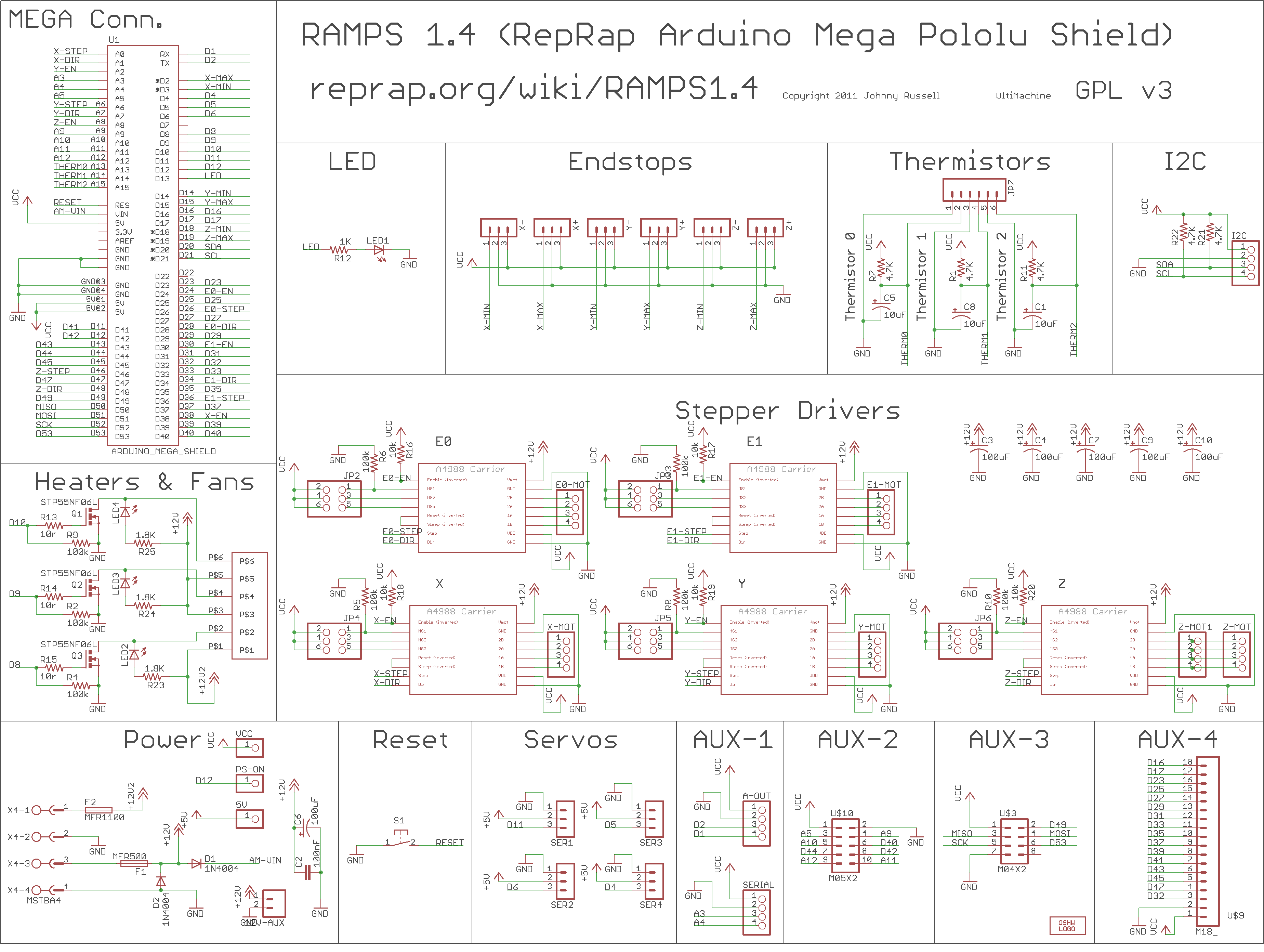
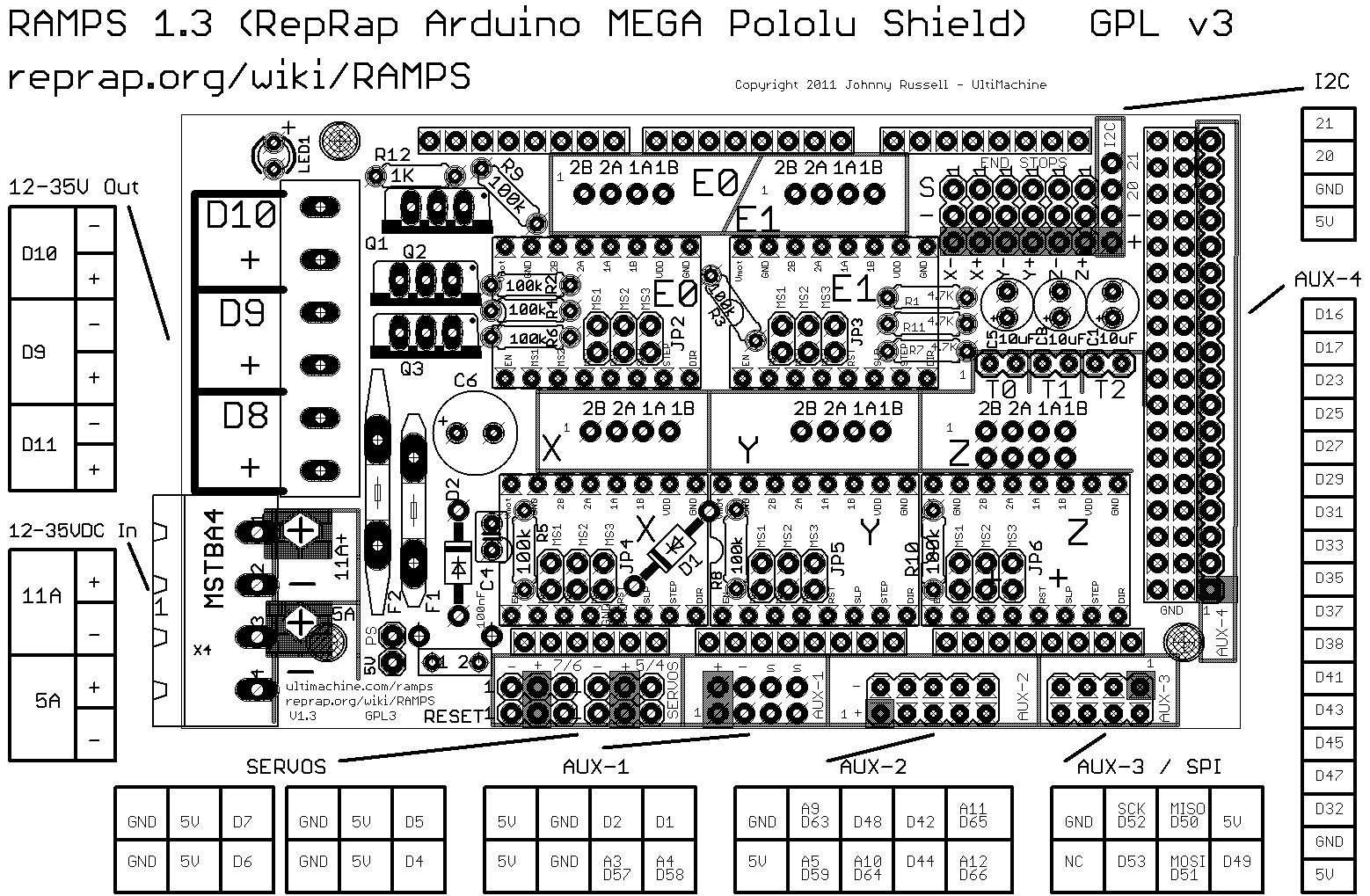
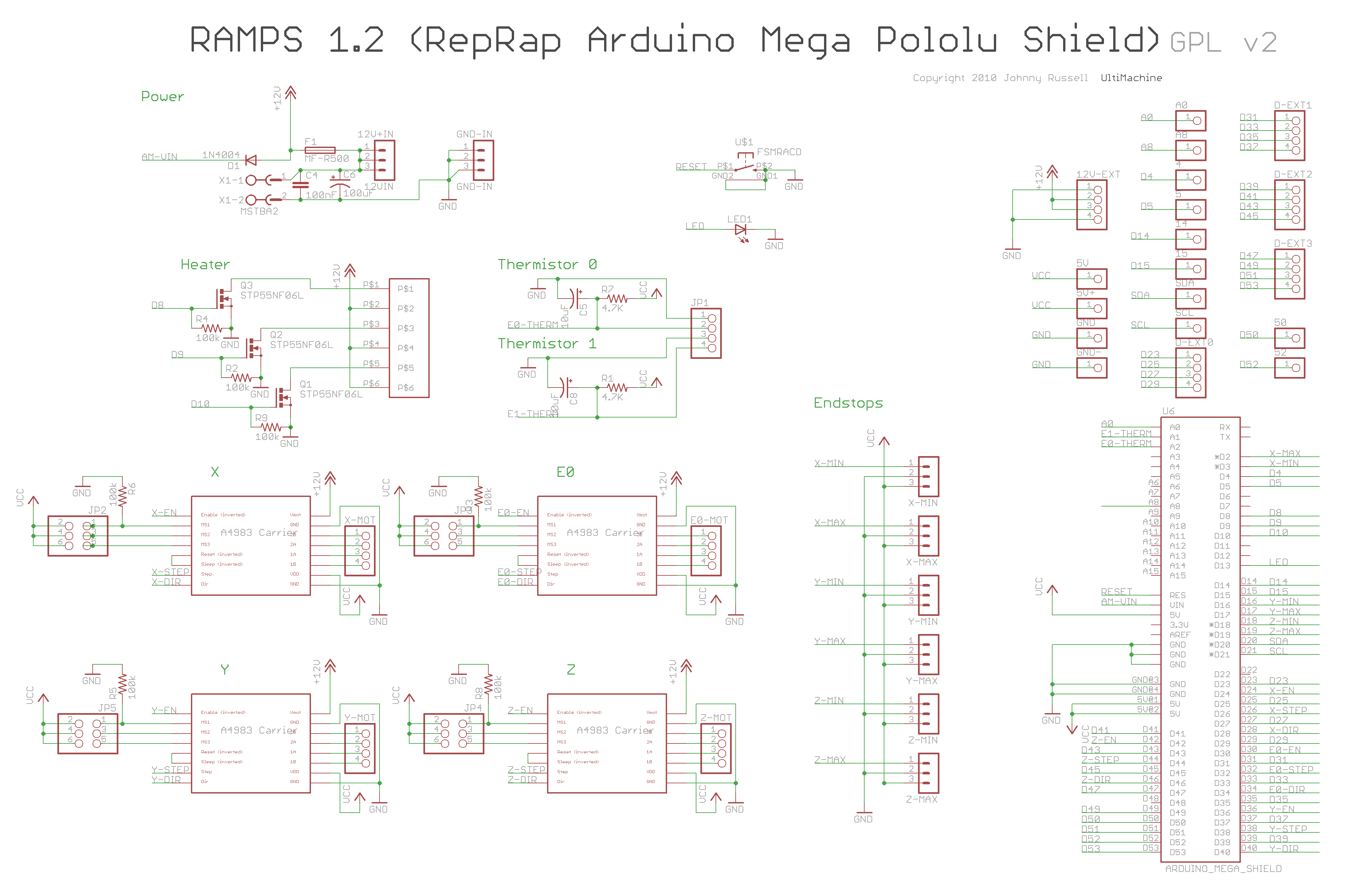
Here are the pin definitions for this board:
|
1 2 3 4 5 6 7 8 9 10 11 12 13 14 15 16 17 18 19 20 21 22 23 24 25 26 27 28 29 30 31 32 33 34 35 36 |
// For RAMPS 1.4 #define X_STEP_PIN 54 #define X_DIR_PIN 55 #define X_ENABLE_PIN 38 #define X_MIN_PIN 3 #define X_MAX_PIN 2 #define Y_STEP_PIN 60 #define Y_DIR_PIN 61 #define Y_ENABLE_PIN 56 #define Y_MIN_PIN 14 #define Y_MAX_PIN 15 #define Z_STEP_PIN 46 #define Z_DIR_PIN 48 #define Z_ENABLE_PIN 62 #define Z_MIN_PIN 18 #define Z_MAX_PIN 19 #define E_STEP_PIN 26 #define E_DIR_PIN 28 #define E_ENABLE_PIN 24 #define SDPOWER -1 #define SDSS 53 #define LED_PIN 13 #define FAN_PIN 9 #define PS_ON_PIN 12 #define KILL_PIN -1 #define HEATER_0_PIN 10 #define HEATER_1_PIN 8 #define TEMP_0_PIN 13 // ANALOG NUMBERING #define TEMP_1_PIN 14 // ANALOG NUMBERING |
Voltage and current notes
Standard RAMPS has a 5A PTC fuse that runs the Arduino Mega, the stepper motor drivers, and the D10 and D9 outputs. This PTC fuse is rated for a max of 30V, however other components on the board are rated for lower voltages, so care should be taken when using any voltage >12V.
Standard RAMPS has a 11A PTC fuse that runs the D8 output. This PTC fuse is rated for a max of 16V.
RAMPS was developed with 12V systems in mind, but it is possible to run it at 24V with various precautions. Most RAMPS boards will happily run at 13.8V or slightly higher with no modification. It is not recommended to exceed 15V for a standard setup, especially if you’ve bought your board from a cheaper supplier who may have used lower spec components than are recommended.
Notes:
- Some variants of RAMPS have real fuses in place of the PTC fuses (eg: GRRF RAMPS). The max current limits will of course be different.
- Many PSU’s overestimate their max current capability. The max current you require will depend on all your components and the voltage you run them at. For a standard RAMPS board, running a machine with a heated bed, your PSU should generate 12V at >16A (20+A is better, as some PSU’s overestimate their capabilities).
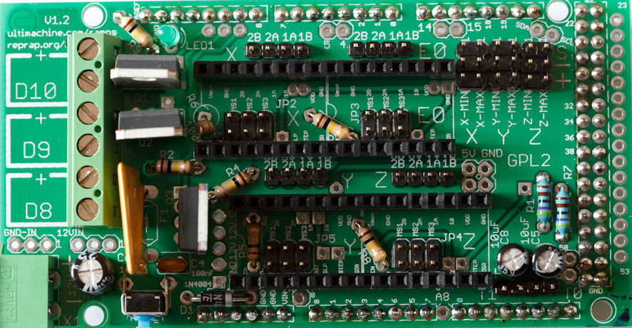
Stepper Driver Boards
Jumpers need to be installed under each stepper driver:
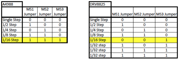
For now the default is 1/16 micro stepping (all jumpers installed under drivers)
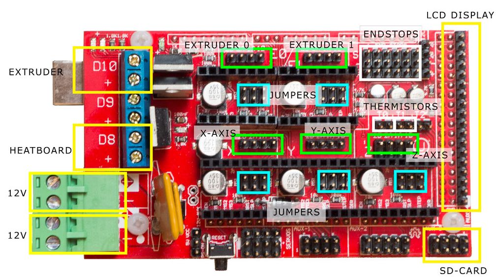
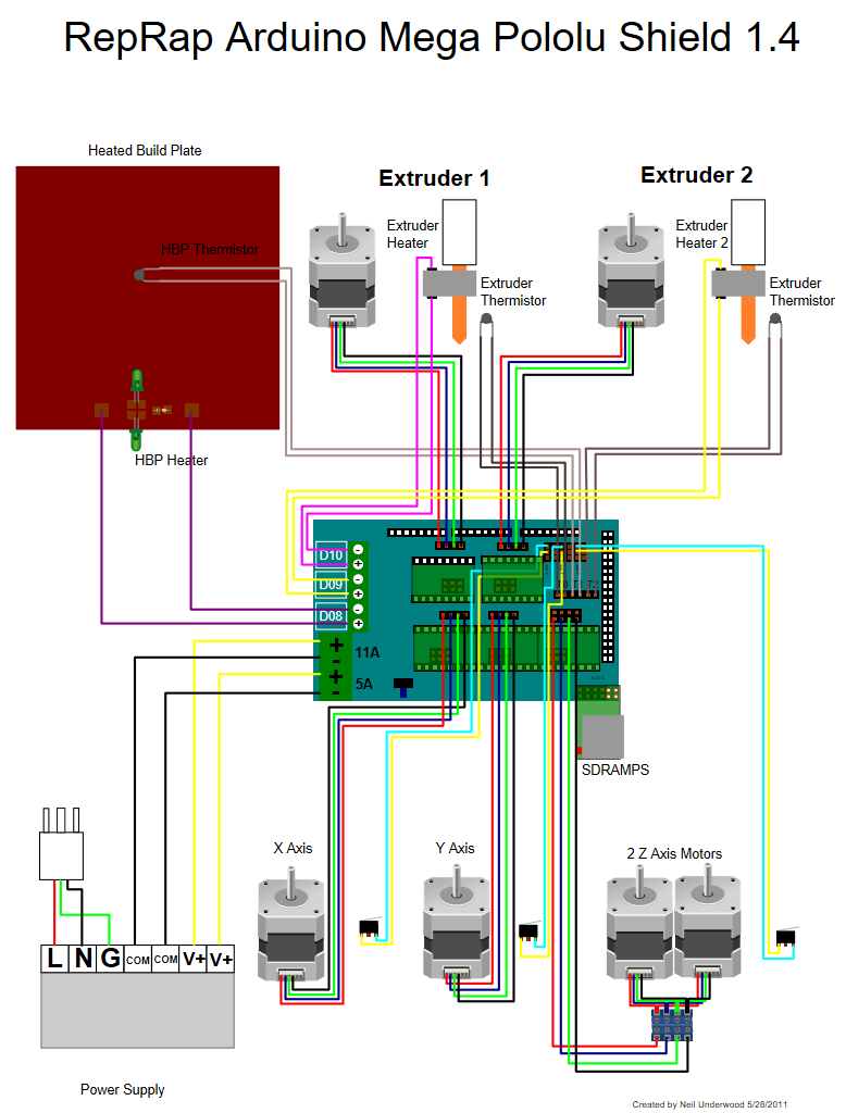
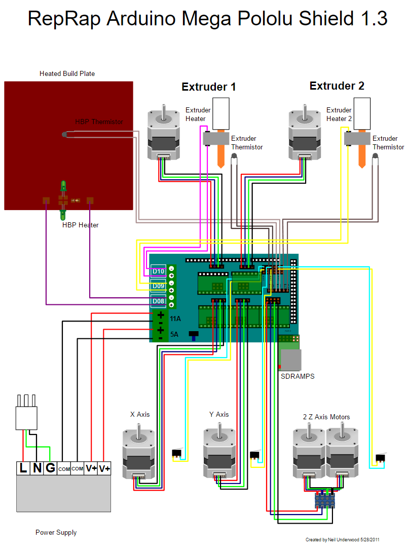
Power Supply
RAMPS is quite happy with the 12 V line from PCPowerSupply. Or you can hack up a 12V laptop power supply, or other 12 V “wall wart” power supply. Make sure that the power supply can output 5A or greater. Additional 11A may be needed for heated bed support.
See Connecting power above.
The 3 pins next to the reset switch are meant to optionally connect to your PSU.
The PS_ON pin is intended to switch your power supply on and off. Many firmwares support pulling this pin low with M80 command to turn the power supply on, and M81 to turn it off. This behavior is desired for ATX power supplies and can be modified in firmware to support 5V high power supplies like those borrowed from an Xbox.
Without D1 installed, or when the 12VIN is not connected, the Arduino gets its power from USB. If you want your kit powered without USB connected you need to solder in D1 OR connect VCC to your PSU.
The VCC pin can be connected to your ATX’s 5Vsb to continuously power the Arduino from your ATX power supply. You will want to make sure that D1 is not installed or cut out. The Arduino is not designed to be powered directly on the VCC rail and the VIN pin at the same time.
If you want to use PS_ON to turn on your power supply then don’t use diode D1, you need your Arduino to be powered from 5Vsb otherwise when no USB is connected the PS_ON pin floats (and your power supply pulses on and off).
The 5V pin in that connector on RAMPS only supplies the 5V to the auxiliary servo connectors. It is designed so that you can jumper it to the VCC pin and use the Arduino’s power supply to supply 5V for extra servos if you are only powered from USB or 5V. Since there is not a lot of extra power from the Arduino’s power supply you can connect it directly to your 5V power supply if you have one. You can also leave this pin not connected if you have no plan to add extra servos.
Maximum Input Voltage
Power Supply without diode
There are three limiting factors to the maximum voltage that you can put into the RAMPS:
- The Arduino Mega maximum input voltage
- Filtering capacitor maximum voltages
- PTC fuse maximum voltages
First, the 1N4004 diode connects the RAMPS input voltage to the Arduino Mega which has a recommended maximum input voltage of 12 volts. If your board does not have this diode soldered in (or if you cut it), you will need to power the Mega through the USB connector or through a separate 5v line, but this allows a higher RAMPS voltage.
Second, most boards use 25v or 35v aluminum electrolytic capactors (C2, C3, C4, C6, C7, C9, and C10). To be safe, you should only go to half of your rated maximum voltage — thus if your board has 35v capacitors (code VZA) then you should use a maximum input of 17.5v. The absolute maximum voltage is determined by the pololu servo drivers, which themselves are limited to 35V.
Third, the MF-R500 (5A) PTC fuse is rated to 30V and the MF-R1100 (11A) PTC fuse is rated to 16V. They will need to be replaced with real fuses.
Power Supply with diode
If your board has a 1N4004 diode soldered in, do not apply more than 12 V to it. Original flavor Arduino Mega are rated to 12 V input. While Arduino Mega 2560 can take 20 V, it is not recommended.
Troubleshooting
- Check List
- RAMPS shield firmly seated on Arduino MEGA
- No stray wires/metal to cause short
- All connections firmly seated, screws tight
- Power connection oriented correctly, connected to RAMPS shield (only USB is connected to MEGA)
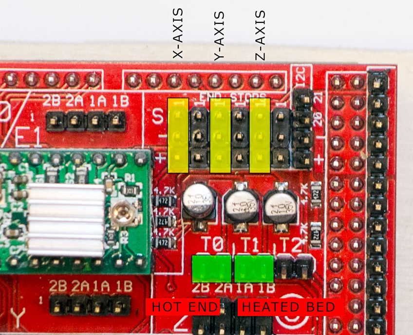
- Thermistor connected to T0
- Firmware uploaded
- Stepper driver potentiometers to a sane setting (maybe 25% from CCW to start, adjust to enough power to drive axis + not overheat)
- Heater wires properly connected
- Power supply functioning properly
- Cannot connect?
- Verify firmware and host software baud rate matches
- Disconnect USB, reconnect, and retry
- It may be a problem with the software you’re using (repsnapper). Try using pronterface.
- Stepper motor getting too hot?
- Adjust the potentiometer (small screw) on the stepper driver in question by rotating the screw counterclockwise to decrease the current going to the stepper motor.
- My fan is not working.
- If you have RAMPs 1.3+ and sprinter firmware (set with the default pins for RAMPs 1.3), try attaching the fan to D9 output.
- In pronterface, the fan can be turned on by using the M106 command and turned off with M107.
- Hot end/heated bed not working.
- Check resistivity by disconnecting from RAMPs and measuring with multimeter
- Check that host software obtains readings from thermistors
Known issues and limitations
1. Overheating 5V regulator on the Arduino Mega
Unless you provide external 5V power or provide 5V through USB cable, the regulator on the Arduino supplies 5V power to the Arduino, the RAMPS (which uses very little) and anything else connected to it. With nothing else powered from the RAMPS, the voltage regulator will run quite warm but not overheat (in tests, I was even able to turn up the input voltage from 12V to 15V without overheating it). With a 20×4 LCD connected, it’s still OK with 12V input. However, if you power a servo or a graphic LCD from the RAMPS, then you will almost certainly overheat the voltage regulator. The usual symptom is that the system will not work unless it is connected to a PC via USB. Or the system may work for a few minutes, hours or days, then fail.
Workarounds include (a) removing D1 on the RAMPS and providing external 5V power to the Arduino/RAMPS; (b) driving the backlight of the graphical LCD from 12V through a series resistor instead of from 5V (a 120 ohm 1W resistor is about right for 12864-type displays), (c) using an Arduino variant with a more powerful voltage regulator (e.g. Taurino).
2. Overheating bed heater MOSFET
The STP55NF06L mosfet is not really adequate to drive a 10A heated bed without a heatsink, so on boards supplied without a heatsink it runs very hot. This is often exacerbated by the previous issue (overheating 5V regulator), which causes the voltage on the 5V rail to be significantly lower than 5V and insufficient to turn the mosfet fully on.
Workaround: either add a heatsink, or (preferably) replace the bed heater mosfet (Q3) by a better type such as IRLB8743PBF or IRLB3034PBF. Also check that the voltage on the 5V rail is close to 5V, preferably at least 4.75V.
3. USB data rate fails to keep up with the printer, resulting in slow, poor-quality prints
This is due to the lack of a true USB port on the Arduino Mega, which uses USB-over-serial instead, and the consequent lack of driver-level flow control. As a result, flow control has to be done at application level by the host program waiting to receive “OK” after sending each command. General purpose host operating systems such as Windows and Linux cannot do this efficiently. Some host programs and operating system combinations work better than others, but this issue has even been reported by some users running Octoprint on a dedicated Raspberry Pi host.
Workaround: print from SD card instead of over USB.
Change Log
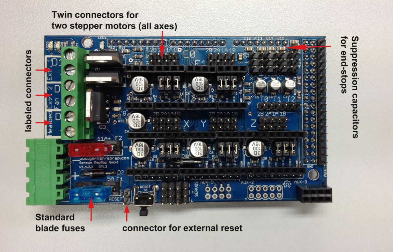
- 1.4.2 has minor changes over RAMPS 1.4. The RAMPS 1.4.2 has below enhancements over 1.4
- Standard blade fuses instead of thermal fuses increasing the heat resilience.
- Current carrying improved by increasing the thickness of the cooper at the PCB from 35 to 70 micro meters.
- Suppression caps added to each end-stop to avoid spurious signals.
- Added an additional connector to XY, E1 and E2 to connect a second stepper motor.
- Connector for external reset added.
- Labeled D8, D9,D10 with Heatbed, Extruder 1 Fan and Extruder 2.
- 1.4 August 4, 2011
- Changed capacitors and resistors to surface mount components
- Added LEDs to mosfet outputs
- Added bulk capacitors for each stepper driver
- Added pull up resistors to enable to override the Pololu drivers default enabled state
- Added mosfet gate resistors
- Added pull-ups for I2C
- Servo1 connector moved to pin 11 to free 7 for ADK
- Fixed thermals
- Servo 5V supply is only connected to VCC if a jumper is added
- Reset switch changed for small footprint
- Moved Aux conectors around a bit and increased board size ~0.1″
- Added some space around Q3 for a small heatsink
- 1.3 May 13, 2011
- Added 5th stepper driver socket
- Added 3rd thermistor circuit
- Added Heated bed circuit w/ 11A PTC fuse, changed to 4 position pluggable input jack to accommodate additional current
- Increased board size to 4″x2.32″
- Pin order on heater outputs changed
- Increased spacing increased to accommodate different connectors
- Added connectors for optional 2 motors on Z driver
- Added connector for PS control
- Improved expansion connector layout
- Moved LED towards corner and added resistor to LED circuit
- No longer optimised for home etching :(
- License changed to GPL v3 or newer
- v1.2 January 04, 2011
- Added 0.1″ motor connector to RAMPS for each driver (motors no longer have to be connected on top of stepper drivers)
- Added breakouts for serial and I2C
- Changed extra power and pin headers around for easier connection to extra boards.
- Lost most extra analog breakouts
- More silk screen and bottom layer fixing
- v1.1 September 30, 2010
- Replaced power barrel jack with plug-able screw terminal
- Added jumpers to select micro-stepping on stepper driver boards
- Added debug LED
- Changed mosfet pins to be compatible with FiveD firmware
- Reduced number of 100uF capacitors to 1
- Added 100nF capacitor to 12V input
- Put auxiliary 12VIN and GNDIN pads in a straight line
- Silk screen and bottom layer cleaned up
- v1.0 Original RAMPS PCB design
- v0.1? Point to point wired Arduino MEGA Prototype shield
Bronnen: reprap.org