Arduino – TWI Keyboard
Hardware
Wat is een TWI Keyboard?
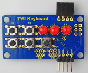
De TWI Keyboard is een eenvoudig te toetsenbord en LED controller board dat kan worden bediend met de TWI (I2C compatibel)-protocol gebruiken. De knoppen zijn allemaal debounced en ondersteuning omhoog, omlaag en toetsherhaling gebeurtenissen. 7 knoppen en 5 LED’s worden ondersteund (twee van de knoppen en lampjes zijn externe, kunnen de overblijvende direct worden gesoldeerd op de print
Het is super-eenvoudig te bedienen met een microcontroller die de TWI-protocol ondersteunt. Bibliotheken voor Arduino en avr-gcc zijn beschikbaar op GitHub .
Slechts vier draden nodig voor gebruik, een voor voeding (draait op zowel 3,3 V en 5 V), een voor aarde, en twee voor de TWI protocol.
Meer informatie is hier te vinden.
Eigenschappen:
– 5 ingang knoppen en 3 LEDs
– 2 poorten voor externe knoppen, evenals 2 poorten voor externe LED’s
– Knoppen zijn allemaal ontdenderd
– Omhoog, omlaag en toetsherhaling evenementen
– LED helderheid kan voor elke LED worden ingesteld
– Automatische pulse functie voor de LEDs
– Arduino library en Low-level avr-gcc library (beschikbaar op GitHub )
– Open Source Firmware (beschikbaar op GitHub )
– Programmeerbare TWI Bus Adres
– On-board ISP header voor het upgraden van firmware
Onderdelen:
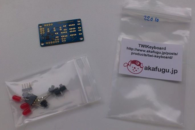
De TWI toetsenbord wordt geleverd als een gedeeltelijk geassembleerd kit, en bestaat uit de volgende onderdelen:
– Gedeeltelijk geassembleerd printplaat (ATTiny2313 en andere opbouwcomponenten komen voorgemonteerd)
– 5x tactiele schakelaars
– 3x LEDs
– 1x 4-pins haakse kop (vrouwelijk)
– 1x 4-pins haakse kop (mannelijk)
Wat heb je nodig?
1) Arduino bibliotheek
Het protocol:
De TWI toetsenbord en LED controller definieert een eenvoudige TWI protocol voor eenvoudige interfacing. Sluit SDA en SCL aan de overeenkomstige SDA en SCL pinnen op uw microcontroller. De TWI protocol vereist pull-up weerstanden, 4.7k of 10k zijn meestal goede waarden, maar voor de korte kabel loopt is het meestal voldoende om ingebouwde pull-up weerstanden van de microcontroller te gebruiken indien beschikbaar.
Het toetsenbord werkt als een TWI slave, het standaard slave-adres is 16, het schrijven van bytes aan het slave-adres activeert het keyboard.
Bytes met waarden tussen 0x80 en 0xff (dwz alle 8-bit waardes MSB 1) zijn gereserveerd voor opdrachten. Elke onbekend commando (alles tussen 0x00 en 0x79) wordt gedefinieerd als ongeldig en heeft geen effect!
Pinout
| Pin TWI Keyboard: | Pin Arduino: |
|---|---|
| SDA | A4 |
| SCL | A5 |
| VCC | +5v |
| GND | GND |
Commandoset (ENG)
All bytes from 0x80 to 0xff are reserved for commands. Some commands are followed by additional data in the form of one of more bytes. For such commands, be sure to send all expected bytes, otherwise the keyboard will be stuck in an invalid state.
0x81: Change slave address. Send this command followed by a new TWI slave address. The valid address range is 0-127 (7-bits). If an invalid address is sent, it will be ignored.
After changing the address, it is neccesary to toggle power to the device: Once the address has been successfully changed, the keyboard will only respond by its new address.
To reset the device to its default address of 16, hold button 1, 2 and 5.
0x82: Clear all LEDs (turning them OFF)
0x83 <led id, brightness>: Set LED brigthness. This command is followed by the id of the LED (numbered from 0 to 5) and then the desired brightness between 0 (off) and 100 (full brightness). The brightness change is instantaneous.
Led id must be between 0 and 5, otherwise the command is treated as a nop (no effect). Any brightness value greater than 100 is treated as 100 (full brightness).
0x84 <led id, pulse on/off>: Set LED to pulse. This command is followed by the id of the LED (numbered from 0 to 5) and then 1 to set pulsing on or 0 to set pulsing off.
Led id must be between 0 and 5, otherwise the command is treated as a nop (no effect)
0x85 <led id, brigthness>: Fade the value of the LED from the current value to a new value. This command is followed by the id of the LED (numbered from 0 to 5) and then the desired brightness between 0 (off) and 255 (full brightness). The brightness change will be gradual.
Led id must be between 0 and 5, otherwise the command is treated as a nop (no effect) Any brightness value greater than 100 is treated as 100 (full brightness).
0x90: Get key up event
0x91: Get key down event
Returns a byte with the key up and key down state of each button respectively, each packed into one bit, with button 1 as MSB and button 7 as LSB.
When the key state is read, the internal state of the key is reset. This means that the user pressing and releasing a single key will result in one key down and one key up event only. If key repeat is set (see command 0x92), the key down event is re-triggered while the key is held down.
0x92 <key id, key repeat>: Set key repeat. Send the command followed by key id (numbered from 0 to 7) and then the key repeat mode.
The following key repeat modes are available:
0: none
1: slow
2: medium slow
3: medium
4: medium fast
5: fast
For key repeat modes between 1 (slow) and 5 (fast) the key down event is re-triggered at a time interval. For key repeat set to 0, only one key down and one key up event is sent.
Key id must be between 0 and 7, key repeat must be between 0 and 5. If any other value is sent, the entire command is treated as a nop and will have no effect.
Default is 0 (none) for all keys.
0xFE: Reset 0xFF: Flush the bus
When initializing the keyboard, send four 0xFF followed by 0xFE to reset the keyboard to a known state. Failure to to this may result in key up and key down events getting mixed up