Arduino Shield – USB 2.0 Host shield
Hardware

Informatie
Arduino USB Host Shield is a board which gives USB interface features to Arduino board and possibility to stack USB devices to Arduino.
Keyboard or mouse can be connected to Arduino with the shield, wireless communication can be done with bluetooth dongle, you can connect to barcode reader and even your phone.MAX3421 is used on board as USB host/SPI converter IC. It is compatible with Arduino Uno and Mega and with 5V/3.3V selection feature, it can be used with 3.3V boards
Specifications
- Works with standard (dual 5/3.3V) and 3.3V-only (for example, Arduino Pro) boards.
- Operates over the extended -40°C to +85°C temperature range
- Complies with USB Specification Revision 2.0 (Full-Speed 12Mbps Peripheral, Full-/Low-Speed 12Mbps/1.5Mbps Host)
Devices that supported by Board
- HID Devices – Klavye, mouse, joystick..
- Game Pads – PS3, PS4, XBOX360, Wii…
- USB-Serial Converters – FTDI, PL-2303, GPS…
- ADK Android Phones and Tablets
- Digital Cameras – Canon EOS, Powershot, Nikon DSLR and P&S
- Storing Devices – Usb Memory, SD card reader, harddisk
- Bluetooth Dongles
Compatible with for Arduino following hardware
- Arduino Uno 328
- Arduino Diecimila / Duemilanove 328
- Arduino Mega 2560 (recommended)
- Arduino Mega 1280
to achieve the FOR Arduino USB HOST function, you can communicate with other USB devices, and support USB HUB function
Shield klaarmaken voor Arduino
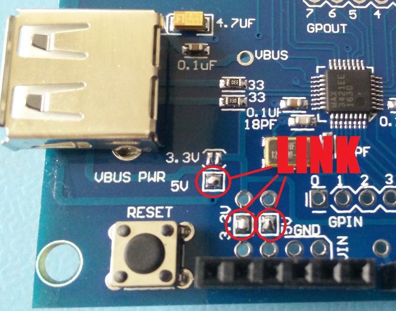
Let op: Voordat deze shield gebruikt kan worden op een arduino UNO/MEGA e.d., moeten er een aantal “bruggen gesoldeerd” worden (de shield is namelijk universeel met andere microcontroller platformen):
– POWER SELECT 3.3v
– POWER SELECT 5V
– VBUS PWR 5V
Overzicht
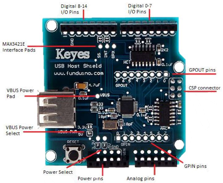
- Power Select 2 solder jumpers marked “5V” and “3.3V”. They are used for different power The configuration shown, when both jumpers are closed, is suitable for official Arduinos, such as UNO, Duemilanove, Mega and Mega 2560. See Power Options section for detailed explanation.
- Power pins are used to connect to power pins of Arduino board. RESET, 3.3V, 5V and GROUND signals from this connector are used.
- Analog pins are not used by the shield. They are provided to simplify mounting and provide pass-through for shields mounted atop of USB Host Shield in a stack.
- GPIN pins. Eight 3.3V general-purpose digital input pins of MAX3421E. They are used primarily to interface with buttons, rotary encoders and such. GPIN pins can also be programmed as a source of MAX3421E interrupt. An example of GPIN use can be seen in digital camera controller
- ICSP connector is used by the shield to send/receive data using SPI interface. SCK, MOSI, MISO and RESET signals from this connector are used.
- GPOUT pins are eight 3.3V general-purpose digital output pins of MAX3421E. They can be used for many purposes; I use it to drive HD44780-compatible character LCD, as can be seen in digital camera controller circuit, as well as this keyboard example. Max_LCD library which is part of standard USB Host library software package uses some of GPOUT pins.
- Digital I/O pins 0-7, like already mentioned analog pins are not used by the shield and provided only for convenience.
- Digital I/O pins 8-13. In this group, the shield in its default configuration uses pins 9 and 10 for INT and SS interface signals. However, standard-sized Arduino boards, such as Duemilanove and UNO have SPI signals routed to pins 11-13 in addition to ICSP connector, therefore shields using pins 11-13 combined with standard-sized Arduinos will interfere with SPI. INT and SS signals can be re-assigned to other pins (see below); SPI signals cannot.
- MAX3421E interface pads are used to make shield modifications easier. Pads for SS and INT signals are routed to Arduino pins 10 and 9 via solder jumpers. In case pin is taken by other shield a re-routing is necessary, a trace is cut and corresponding pad is connected with another suitable Arduino I/O ping with a wire. To undo the operation, a wire is removed and jumper is closed. See interface modifications section for more information. GPX pin is not used and is available on a separate pad to facilitate further expansion. It can be used as a second interrupt pin of MAX3421E.
- VBUS power pad. This pad is used in advanced power configurations, described in Power Options section.
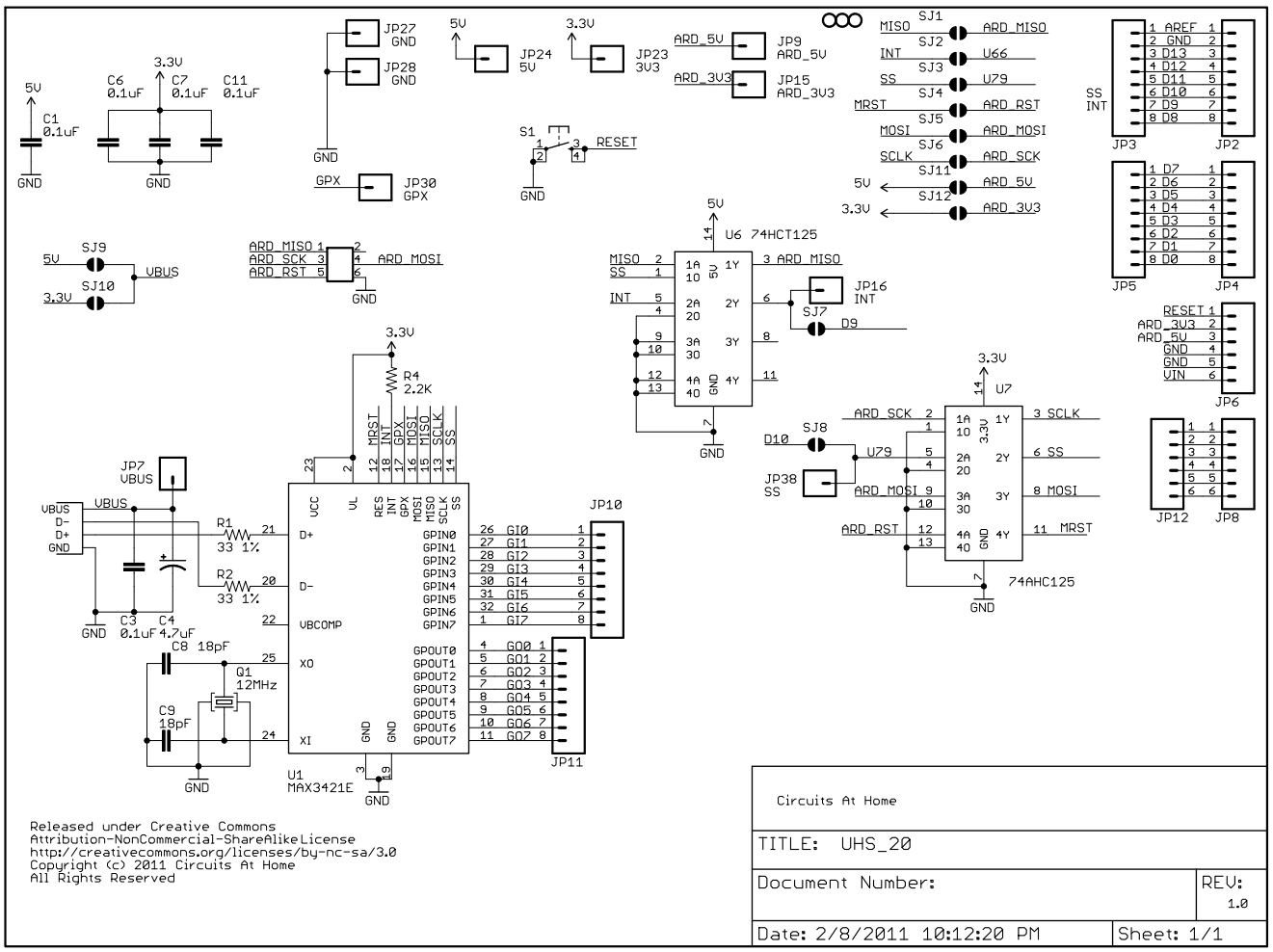
Schema
Script Toetsenbord

Dit is het voorbeeldscript dat bijgeleverd wordt bij de bibliotheek om een HID toetsenbord uit te lezen:
|
1 2 3 4 5 6 7 8 9 10 11 12 13 14 15 16 17 18 19 20 21 22 23 24 25 26 27 28 29 30 31 32 33 34 35 36 37 38 39 40 41 42 43 44 45 46 47 48 49 50 51 52 53 54 55 56 57 58 59 60 61 62 63 64 65 66 67 68 69 70 71 72 73 74 75 76 77 78 79 80 81 82 83 84 85 86 87 88 89 90 91 92 93 94 95 96 97 98 99 100 101 102 103 104 105 106 107 108 109 110 111 112 113 114 115 116 117 118 119 120 121 122 123 124 |
#include <hidboot.h> #include <usbhub.h> // Satisfy the IDE, which needs to see the include statment in the ino too. #ifdef dobogusinclude #include <spi4teensy3.h> #endif #include <SPI.h> class KbdRptParser : public KeyboardReportParser { void PrintKey(uint8_t mod, uint8_t key); protected: void OnControlKeysChanged(uint8_t before, uint8_t after); void OnKeyDown (uint8_t mod, uint8_t key); void OnKeyUp (uint8_t mod, uint8_t key); void OnKeyPressed(uint8_t key); }; void KbdRptParser::PrintKey(uint8_t m, uint8_t key) { MODIFIERKEYS mod; *((uint8_t*)&mod) = m; Serial.print((mod.bmLeftCtrl == 1) ? "C" : " "); Serial.print((mod.bmLeftShift == 1) ? "S" : " "); Serial.print((mod.bmLeftAlt == 1) ? "A" : " "); Serial.print((mod.bmLeftGUI == 1) ? "G" : " "); Serial.print(" >"); PrintHex<uint8_t>(key, 0x80); Serial.print("< "); Serial.print((mod.bmRightCtrl == 1) ? "C" : " "); Serial.print((mod.bmRightShift == 1) ? "S" : " "); Serial.print((mod.bmRightAlt == 1) ? "A" : " "); Serial.println((mod.bmRightGUI == 1) ? "G" : " "); }; void KbdRptParser::OnKeyDown(uint8_t mod, uint8_t key) { Serial.print("DN "); PrintKey(mod, key); uint8_t c = OemToAscii(mod, key); if (c) OnKeyPressed(c); } void KbdRptParser::OnControlKeysChanged(uint8_t before, uint8_t after) { MODIFIERKEYS beforeMod; *((uint8_t*)&beforeMod) = before; MODIFIERKEYS afterMod; *((uint8_t*)&afterMod) = after; if (beforeMod.bmLeftCtrl != afterMod.bmLeftCtrl) { Serial.println("LeftCtrl changed"); } if (beforeMod.bmLeftShift != afterMod.bmLeftShift) { Serial.println("LeftShift changed"); } if (beforeMod.bmLeftAlt != afterMod.bmLeftAlt) { Serial.println("LeftAlt changed"); } if (beforeMod.bmLeftGUI != afterMod.bmLeftGUI) { Serial.println("LeftGUI changed"); } if (beforeMod.bmRightCtrl != afterMod.bmRightCtrl) { Serial.println("RightCtrl changed"); } if (beforeMod.bmRightShift != afterMod.bmRightShift) { Serial.println("RightShift changed"); } if (beforeMod.bmRightAlt != afterMod.bmRightAlt) { Serial.println("RightAlt changed"); } if (beforeMod.bmRightGUI != afterMod.bmRightGUI) { Serial.println("RightGUI changed"); } } void KbdRptParser::OnKeyUp(uint8_t mod, uint8_t key) { Serial.print("UP "); PrintKey(mod, key); } void KbdRptParser::OnKeyPressed(uint8_t key) { Serial.print("ASCII: "); Serial.println((char)key); }; USB Usb; //USBHub Hub(&Usb); HIDBoot<USB_HID_PROTOCOL_KEYBOARD> HidKeyboard(&Usb); KbdRptParser Prs; void setup() { Serial.begin( 115200 ); #if !defined(__MIPSEL__) while (!Serial); // Wait for serial port to connect - used on Leonardo, Teensy and other boards with built-in USB CDC serial connection #endif Serial.println("Start"); if (Usb.Init() == -1) Serial.println("OSC did not start."); delay( 200 ); HidKeyboard.SetReportParser(0, &Prs); } void loop() { Usb.Task(); } |
Output:
|
1 2 3 4 5 6 7 8 9 10 11 12 13 14 15 16 |
Start DN >0B< ASCII: h UP >0B< DN >04< ASCII: a UP >04< DN >0F< ASCII: l UP >0F< DN >0F< ASCII: l UP >0F< DN >12< ASCII: o UP >12< |
Script Muis
![]()
Dit is het voorbeeldscript dat bijgeleverd wordt bij de bibliotheek om een HID toetsenbord uit te lezen:
|
1 2 3 4 5 6 7 8 9 10 11 12 13 14 15 16 17 18 19 20 21 22 23 24 25 26 27 28 29 30 31 32 33 34 35 36 37 38 39 40 41 42 43 44 45 46 47 48 49 50 51 52 53 54 55 56 57 58 59 60 61 62 63 64 65 66 67 68 69 70 71 72 73 74 75 76 77 78 |
#include <hidboot.h> #include <usbhub.h> // Satisfy the IDE, which needs to see the include statment in the ino too. #ifdef dobogusinclude #include <spi4teensy3.h> #endif #include <SPI.h> class MouseRptParser : public MouseReportParser { protected: void OnMouseMove (MOUSEINFO *mi); void OnLeftButtonUp (MOUSEINFO *mi); void OnLeftButtonDown (MOUSEINFO *mi); void OnRightButtonUp (MOUSEINFO *mi); void OnRightButtonDown (MOUSEINFO *mi); void OnMiddleButtonUp (MOUSEINFO *mi); void OnMiddleButtonDown (MOUSEINFO *mi); }; void MouseRptParser::OnMouseMove(MOUSEINFO *mi) { Serial.print("dx="); Serial.print(mi->dX, DEC); Serial.print(" dy="); Serial.println(mi->dY, DEC); }; void MouseRptParser::OnLeftButtonUp (MOUSEINFO *mi) { Serial.println("L Butt Up"); }; void MouseRptParser::OnLeftButtonDown (MOUSEINFO *mi) { Serial.println("L Butt Dn"); }; void MouseRptParser::OnRightButtonUp (MOUSEINFO *mi) { Serial.println("R Butt Up"); }; void MouseRptParser::OnRightButtonDown (MOUSEINFO *mi) { Serial.println("R Butt Dn"); }; void MouseRptParser::OnMiddleButtonUp (MOUSEINFO *mi) { Serial.println("M Butt Up"); }; void MouseRptParser::OnMiddleButtonDown (MOUSEINFO *mi) { Serial.println("M Butt Dn"); }; USB Usb; USBHub Hub(&Usb); HIDBoot<USB_HID_PROTOCOL_MOUSE> HidMouse(&Usb); MouseRptParser Prs; void setup() { Serial.begin( 115200 ); #if !defined(__MIPSEL__) while (!Serial); // Wait for serial port to connect - used on Leonardo, Teensy and other boards with built-in USB CDC serial connection #endif Serial.println("Start"); if (Usb.Init() == -1) Serial.println("OSC did not start."); delay( 200 ); HidMouse.SetReportParser(0, &Prs); } void loop() { Usb.Task(); } |
Output:
|
1 2 3 4 5 6 7 8 9 10 11 12 13 14 15 16 17 18 |
Start L Butt Dn L Butt Up R Butt Dn R Butt Up M Butt Dn M Butt Up dx=0 dy=1 dx=3 dy=2 dx=6 dy=1 dx=7 dy=1 dx=3 dy=1 dx=2 dy=0 dx=0 dy=1 dx=1 dy=0 dx=0 dy=-1 dx=1 dy=0 dx=1 dy=-1 |
Script Joystick

Dit is het voorbeeldscript dat bijgeleverd wordt bij de bibliotheek om een HID Joystick uit te lezen:
|
1 2 3 4 5 6 7 8 9 10 11 12 13 14 15 16 17 18 19 20 21 22 23 24 25 26 27 28 29 30 31 32 33 34 35 36 37 |
#include <usbhid.h> #include <hiduniversal.h> #include <usbhub.h> // Satisfy IDE, which only needs to see the include statment in the ino. #ifdef dobogusinclude #include <spi4teensy3.h> #endif #include <SPI.h> #include "hidjoystickrptparser.h" USB Usb; USBHub Hub(&Usb); HIDUniversal Hid(&Usb); JoystickEvents JoyEvents; JoystickReportParser Joy(&JoyEvents); void setup() { Serial.begin(115200); #if !defined(__MIPSEL__) while (!Serial); // Wait for serial port to connect - used on Leonardo, Teensy and other boards with built-in USB CDC serial connection #endif Serial.println("Start"); if (Usb.Init() == -1) Serial.println("OSC did not start."); delay(200); if (!Hid.SetReportParser(0, &Joy)) ErrorMessage<uint8_t > (PSTR("SetReportParser"), 1); } void loop() { Usb.Task(); } |
Output:
|
1 2 3 4 5 6 7 8 9 10 11 12 13 14 15 16 17 18 19 20 21 22 23 24 25 26 27 28 29 30 31 32 33 34 35 36 37 38 39 40 41 42 43 44 45 46 |
Up: 12 Up: 6 Dn: 7 Dn: 8 Up: 9 Up: 10 Dn: 9 Up: 11 Up: 7 Up: 8 Up: 9 Dn: 5 Dn: 6 Dn: 8 Dn: 10 Up: 5 Up: 6 Up: 8 Up: 10 Dn: 12 X1: 01 Y1: 00 X2: 00 Y2: 40 Rz: 00 X1: 01 Y1: 00 X2: 00 Y2: 00 Rz: 00 X1: 01 Y1: 00 X2: 40 Y2: 00 Rz: 00 X1: 01 Y1: 00 X2: 00 Y2: 00 Rz: 00 X1: 01 Y1: 00 X2: 00 Y2: 04 Rz: 00 X1: 01 Y1: 00 X2: 00 Y2: 06 Rz: 00 X1: 01 Y1: 00 X2: 00 Y2: 0E Rz: 00 X1: 01 Y1: 00 X2: 00 Y2: 0F Rz: 00 X1: 01 Y1: 00 X2: 20 Y2: 0F Rz: 00 X1: 01 Y1: 00 X2: 20 Y2: 1F Rz: 00 X1: 01 Y1: 00 X2: 60 Y2: 1F Rz: 00 X1: 01 Y1: 00 X2: 20 Y2: 1F Rz: 00 X1: 01 Y1: 00 X2: 20 Y2: 1E Rz: 00 X1: 01 Y1: 00 X2: 20 Y2: 9E Rz: 00 X1: 01 Y1: 00 X2: 20 Y2: DE Rz: 00 X1: 01 Y1: 00 X2: 20 Y2: 9E Rz: 00 X1: 01 Y1: 00 X2: 20 Y2: DE Rz: 00 X1: 01 Y1: 00 X2: 00 Y2: DE Rz: 00 X1: 01 Y1: 00 X2: 00 Y2: 9E Rz: 00 X1: 01 Y1: 00 X2: 00 Y2: DE Rz: 00 X1: 01 Y1: 00 X2: 10 Y2: DE Rz: 00 X1: 01 Y1: 00 X2: 30 Y2: DE Rz: 00 X1: 01 Y1: 00 X2: 30 Y2: DC Rz: 00 X1: 01 Y1: 00 X2: 10 Y2: C8 Rz: 00 X1: 01 Y1: 00 X2: 00 Y2: 80 Rz: 00 X1: 01 Y1: 00 X2: 00 Y2: 00 Rz: 00 |
Script Barcode scanner
![]()
We hebben dit script gevonden op het internet om een USB barcode scanner uit te lezen, de scanner geeft de nummers door als een toetsenbord gevolgd door een enter op het eind (soort macro)
|
1 2 3 4 5 6 7 8 9 10 11 12 13 14 15 16 17 18 19 20 21 22 23 24 25 26 27 28 29 30 31 32 33 34 35 36 37 38 39 40 41 42 43 44 45 46 47 48 49 50 51 52 53 54 55 56 57 58 59 60 61 62 63 64 65 66 67 68 69 70 71 72 73 74 75 76 77 78 79 80 81 82 83 84 85 86 |
#include <usbhid.h> #include <usbhub.h> #include <hiduniversal.h> #include <hidboot.h> #include <SPI.h> class MyParser : public HIDReportParser { public: MyParser(); void Parse(USBHID *hid, bool is_rpt_id, uint8_t len, uint8_t *buf); protected: uint8_t KeyToAscii(bool upper, uint8_t mod, uint8_t key); virtual void OnKeyScanned(bool upper, uint8_t mod, uint8_t key); virtual void OnScanFinished(); }; MyParser::MyParser() {} void MyParser::Parse(USBHID *hid, bool is_rpt_id, uint8_t len, uint8_t *buf) { // If error or empty, return if (buf[2] == 1 || buf[2] == 0) return; for (uint8_t i = 7; i >= 2; i--) { // If empty, skip if (buf[i] == 0) continue; // If enter signal emitted, scan finished if (buf[i] == UHS_HID_BOOT_KEY_ENTER) { OnScanFinished(); } // If not, continue normally else { // If bit position not in 2, it's uppercase words OnKeyScanned(i > 2, buf, buf[i]); } return; } } uint8_t MyParser::KeyToAscii(bool upper, uint8_t mod, uint8_t key) { // Letters if (VALUE_WITHIN(key, 0x04, 0x1d)) { if (upper) return (key - 4 + 'A'); else return (key - 4 + 'a'); } // Numbers else if (VALUE_WITHIN(key, 0x1e, 0x27)) { return ((key == UHS_HID_BOOT_KEY_ZERO) ? '0' : key - 0x1e + '1'); } return 0; } void MyParser::OnKeyScanned(bool upper, uint8_t mod, uint8_t key) { uint8_t ascii = KeyToAscii(upper, mod, key); Serial.print((char)ascii); } void MyParser::OnScanFinished() { Serial.println(" - Finished"); } USB Usb; USBHub Hub(&Usb); HIDUniversal Hid(&Usb); MyParser Parser; void setup() { Serial.begin( 115200 ); Serial.println("Start"); if (Usb.Init() == -1) { Serial.println("OSC did not start."); } delay( 200 ); Hid.SetReportParser(0, &Parser); } void loop() { Usb.Task(); } |
Output:
|
1 2 3 4 |
Start 8718452139774 - Finished 87167054 - Finished 3607345373515 - Finished |
Bronnen:
github.com/felis/USB_Host_Shield_2.0
Downloads:
Arduino library @ github.com/felis/USB_Host_Shield_2.0
- USB_Host_Shield_2.0-1.3.2.7z 184,71 kb
- USB_Host_Shield_2.0-1.3.1.7z 182,93 kb
- USB_Host_Shield_2.0-1.3.0.7z 182,12 kb
- USB_Host_Shield_2.0-1.2.1.7z 172,27 kb
- USB_Host_Shield_2.0-1.2.0.7z 172,22 kb
- USB_Host_Shield_2.0-1.1.1.7z 171,25 kb
- USB_Host_Shield_2.0-1.1.0.7z 170,68 kb
- USB_Host_Shield_2.0-1.0.0.7z 168,99 kb
- UHS_20r10 eagle files.7z 21,98 kb
- UHS_20 schema.7z 24,92 kb