ATtiny13 Basics – LED dimmen met PWM
In dit voorbeeld gaan we een LEDje laten dimmen op de ATtiny13.
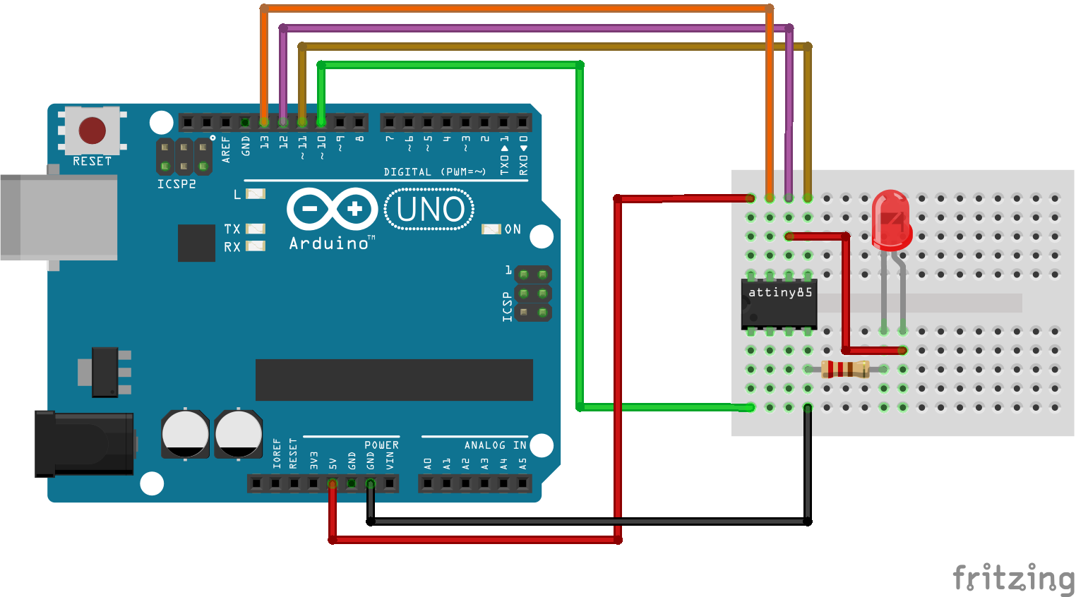
Sluit het ledje aan volgens onderstaand schema (in dit schema is ook de bedrading voor het programmeren via de ISP meegenomen):
Let op: Het weerstandje is belangrijk, deze beperkt de stroom door de LED, als je deze niet gebruikt gaat het LEDje (snel) stuk!
De code om de LED te laten in- en uit-faden met een loop (ipv een potmeter) heb ik aangepast van adnbr@Github:
|
1 2 3 4 5 6 7 8 9 10 11 12 13 14 15 16 17 18 19 20 21 22 23 24 25 26 27 28 29 30 31 |
#include <avr/io.h> #define F_CPU 9600000 #define LED PB1 int i; int richting = 0; int main (void) { int adc_in; DDRB |= (1 << LED); ADMUX |= (1 << MUX0); ADMUX |= (1 << ADLAR); ADCSRA |= (1 << ADPS1) | (1 << ADPS0) | (1 << ADEN); TCCR0B |= (1 << CS01); TCCR0A |= (1 << WGM01) | (1 << WGM00); TCCR0A |= (1 << COM0B1); while (1) { if (richting == 1) { i = i + 1; if (i > 254) { richting = 0; } delay(10); OCR0B = i; } if (richting == 0) { i = i - 1; if (i < 2) { richting = 1; } delay(10); OCR0B = i; } } } |
Orginele code
Bron adnbr@github
|
1 2 3 4 5 6 7 8 9 10 11 12 13 14 15 16 17 18 19 20 21 22 23 24 25 26 27 28 29 30 31 32 33 34 35 36 37 38 39 40 41 42 43 44 45 46 47 48 49 50 51 52 53 54 55 56 57 58 59 60 61 62 63 64 65 66 67 68 69 70 71 72 73 74 75 76 77 78 79 |
/* --------------------------------------------------------------------- * PWM LED Brightness control for ATtiny13. * Datasheet for ATtiny13: http://www.atmel.com/images/doc2535.pdf * * Pin configuration - * PB1/OC0B: LED output (Pin 6) * PB2/ADC1: Potentiometer input (Pin 7) * * ~100 bytes. * * Find out more: http://bit.ly/1eBhqHc * -------------------------------------------------------------------*/ // 9.6 MHz, built in resonator #define F_CPU 9600000 #define LED PB1 #include <avr/io.h> void adc_setup (void) { // Set the ADC input to PB2/ADC1 ADMUX |= (1 << MUX0); ADMUX |= (1 << ADLAR); // Set the prescaler to clock/128 & enable ADC // At 9.6 MHz this is 75 kHz. // See ATtiny13 datasheet, Table 14.4. ADCSRA |= (1 << ADPS1) | (1 << ADPS0) | (1 << ADEN); } int adc_read (void) { // Start the conversion ADCSRA |= (1 << ADSC); // Wait for it to finish while (ADCSRA & (1 << ADSC)); return ADCH; } void pwm_setup (void) { // Set Timer 0 prescaler to clock/8. // At 9.6 MHz this is 1.2 MHz. // See ATtiny13 datasheet, Table 11.9. TCCR0B |= (1 << CS01); // Set to 'Fast PWM' mode TCCR0A |= (1 << WGM01) | (1 << WGM00); // Clear OC0B output on compare match, upwards counting. TCCR0A |= (1 << COM0B1); } void pwm_write (int val) { OCR0B = val; } int main (void) { int adc_in; // LED is an output. DDRB |= (1 << LED); adc_setup(); pwm_setup(); while (1) { // Get the ADC value adc_in = adc_read(); // Now write it to the PWM counter pwm_write(adc_in); } } |
Toelichting (eng)
I want to use an ATtiny13 to control the brightness of an LED light source (as a controller for this) and therefore need to control both the ADC input and the PWM output. This example is very simple, but will hopefully serve as a jumping off point for people new to the ADC and PWM systems in AVR microcontrollers.
First let’s take a look at a basic overview of the circuit we are using:
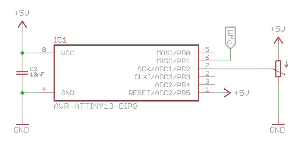
It’s very simple, and it’s certainly not going to win any awards for style or efficiency. There are spare pins left over which could be utilised elsewhere should the need arise – in the microscope board I’ve broken these out into an extra header.
From the schematic we can see that the PWM output to the LED will be on pin 6 (PB1) and the ADC input we are using is on pin 7 (ADC1, PB2).
Setup the ADC
Selecting the ADC input is easy – look at Table 14.3 on page 92 of the datasheet for the correct mux settings.
|
1 2 3 |
// Set the ADC input to PB2/ADC1, left adjust result ADMUX |= (1 << MUX0); ADMUX |= (1 << ADLAR); |
Once we’ve selected the ADC channel and set the result to be left adjusted (more on that later) we set the prescaler for the ADC clock relative to the system clock and enable the system. Table 14.4 on page 93 has the values for the prescaler selection.
Put simply the prescaler divides the system clock speed the amount prescribed by the table – the ideal ADC clock speed is between 50 kHz and 200 kHz for the full 10 bits of resolution. The faster the clock, the faster the conversion takes place.
|
1 2 |
// Set the prescaler to clock/128 & enable ADC ADCSRA |= (1 << ADPS1) | (1 << ADPS0) | (1 << ADEN); |
In our case the system clock is 9.6 MHz divided by 8 to achieve an ADC clock running at 75 kHz.
Let’s quickly package this up into a method we can call from the start of the main loop and move on to making a reading.
|
1 2 3 4 5 6 7 8 9 |
void adc_setup (void) { // Set the ADC input to PB2/ADC1 ADMUX |= (1 << MUX0); ADMUX |= (1 << ADLAR); // Set the prescaler to clock/128 & enable ADC ADCSRA |= (1 << ADPS1) | (1 << ADPS0) | (1 << ADEN); } |
ADLAR, or how to achieve 10 bit results
The PWM module is only capable of 8-bit resolution, so why bother reading a full 10-bit ADC value? The ADLAR bit in the ADMUX register rearranges the results register (see page 93 again) to let you discard the lowest two bits of information by reading the ADCH result register.
If you do want 10-bit resolution, do not set the ADLAR bit and instead of reading ADCHyou should read ADC.
Make a reading
We have to wait for a conversion to finish before we can read it – here I’m going to use a busy wait loop which continually checks for the ADSC bit in the ADCSRA register to be cleared but there is also the facility to have an interrupt thrown when the ADC has completed a conversion. I will write about that at a later date.
|
1 |
while (ADCSRA & (1 << ADSC)); |
Each conversion takes 13 ADC clock cycles (bar the first one, which takes 25.) Once the conversion is completed we need to grab the result from the result register, ADCH.
Starting a new conversion is as easy as setting the ADSC bit. And reading a 10 bit result (if you want it that is, see the section above about ADLAR) is remarkably simple – a preprocessor macro built into the avr-gcc libraries provides the helpful ADC pseudo-register that can be used to obtain the full 10 bit value.
|
1 2 3 4 5 6 7 8 9 10 |
int adc_read (void) { // Start the conversion ADCSRA |= (1 << ADSC); // Wait for it to finish while (ADCSRA & (1 << ADSC)); return ADCH; } |
So far…
We have a way to read the value of the ADC pin, but we can’t really do anything useful with the data we get. Here’s what we’ve got so far:
|
1 2 3 4 5 6 7 8 9 10 11 12 13 14 15 16 17 18 19 20 21 22 23 24 25 26 27 28 29 30 31 32 33 34 35 36 |
// 9.6 MHz, built in resonator #define F_CPU 9600000 #include <avr/io.h> void adc_setup (void) { // Set the ADC input to PB2/ADC1 ADMUX |= (1 << MUX0); ADMUX |= (1 << ADLAR); // Set the prescaler to clock/128 & enable ADC ADCSRA |= (1 << ADPS1) | (1 << ADPS0) | (1 << ADEN); } int adc_read (void) { // Start the conversion ADCSRA |= (1 << ADSC); // Wait for it to finish while (ADCSRA & (1 << ADSC)); return ADCH; } int main (void) { int adc_in; adc_setup(); while (1) { adc_in = adc_read(); } } |
Setting up the PWM
If you are unsure as to what pulse width modulation is I suggest you find out before continuing onwards.
In the circuit we are running here it is possible to simply connect the LED directly to the pin with an appropriate resistor to ground, and the pin will run it. For the microscope project we will be using a MOSFET to allow the passing of more current, but for this experimental purpose the LED will do perfectly.
Before we get ahead of ourselves though, let’s find out a bit about the ATTiny13’s PWM functionality.
OCOA and OCOB
This AVR microcontroller has two channels with 8-bit PWM capability – PB0/OCOA (pin 5) and PB1/OCOB (pin 6), both running from Timer 0.
|
1 2 3 |
// Set Timer 0 prescaler to clock/8. // At 9.6 MHz this is 1.2 MHz. TCCR0B |= (1 << CS01) | (1 << CS00); |
Just like the ADC there is a prescaler that adjusts how fast Timer 0 counts relative to the system clock speed. Controlled by the TCCR0B register this prescaler determines the maximum frequency of the PWM signal later on, according to this equation –
![]()
Where P is the prescaler factor, and M depends on the PWM mode you choose – it is either 256 (Fast PWM) or 512 (Phase Correct PWM.) We will be using the “Fast” mode, which counts from 0 to 255 repeatedly to give a frequency of 4.7 kHz – more than fast enough to avoid eye-strain-inducing flicker.
Fast PWM Mode
Change the timer to Fast PWM mode by selecting the appropriate bits from Table 11.8, and tell it to set the output value low (clear the bit) when the timer equals the value of OCR0B.
|
1 2 3 4 5 |
// Set to 'Fast PWM' mode TCCR0A |= (1 << WGM01) | (1 << WGM00); // Clear OC0B output on compare match, upwards counting. TCCR0A |= (1 << COM0B1); |
To explain what is actually happening here, take a look at the graphic below. The black sawtooth line is the value of the Timer 0 counter which counts to 255 then resets to 0. If we set the PWM value to reasonably high, say 200 (the red horizontal line) then the PWM output will be equivalent to the red square wave below. As the output is high the majority of the time the LED will be quite bright.
Conversely if we set the PWM value to quite low (the yellow horizontal line) then the PWM output will change accordingly and the LED will be quite dim. Try to imagine each section of the sawtooth occuring in approximately 200 μs.
To then actually set the PWM duty cycle it is a matter of assigning a value to the OCR0Bregister.
|
1 2 3 4 |
void pwm_write (int val) { OCR0B = val; } |
Now would be a good time to package all the PWM setup code into its own method. I’ll leave that up to you as we move on to combining the ADC and PWM. Remember to set the LED pin, PB1 as an output.
ADC and PWM together, in harmony
The ADC is set up, the PWM is ready to go and to get one talk to the other is as simple as just copying a value across:
|
1 2 3 4 5 6 7 8 9 10 11 12 13 14 15 16 17 18 19 20 21 |
#define LED PB1 // ... adc_setup, adc_read, pwm_setup, pwm_write ... int main (void) { int adc_in; // LED is an output. DDRB |= (1 << LED); adc_setup(); pwm_setup(); while (1) { // Get the ADC value adc_in = adc_read(); // Now write it to the PWM counter pwm_write(adc_in); } } |
It’s as simple as that. You may find you need to do some form of filtering to the ADC value, especially if the analog portion of your circuit is quite noisy, or perhaps there is a specific condition you want to fulfil before the PWM output is turned on. I’ll leave that up to you.
Bron: adnbr.co.uk