Berekening – Inductie
![]()
De “micometals tool” is getest op windows 10, de andere tools zijn van 1992 (incl source) en moet men bijvoorbeeld in een Windows XP (VM box) starten.
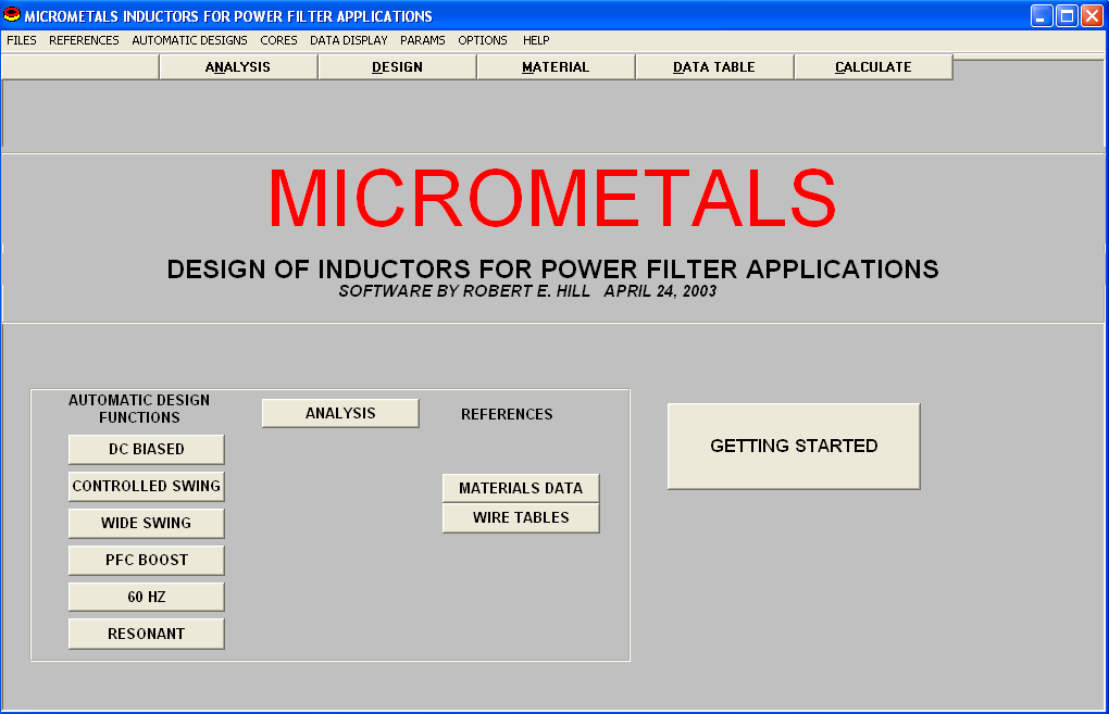
Micrometals tool
Informatie (ENG)
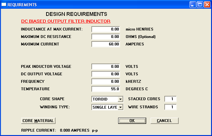
POWER SUPPLY OUTPUT (DC BIASED) FILTER INDUCTORS: Used for design of inductors for power filtering and general purpose applications with DC bias current and a superimposed AC voltage. As a minimum, the user must specify the desired inductance in microhenries and a maximum dc or ac operating current. An optional DC winding resistance limit can also be entered. If zero is entered for the MAXIMUM RESISTANCE, the value is ignored by the program. If no AC operating conditions are specified, the program selects a core and winding to satisfy the inductance and (optionally) resistance, current density, minimum percent permeability, and temperature rise limits. Wire size is calculated to fill the available window. The Peak-to-peak ac ripple current is displayed for the user’s information. Copper loss is calculated based on the specified DC bias and the ambient temperature. If AC voltages and frequency are specified the core loss is calculated based on the average induced voltage at the frequency specified.
CONTROLLED INDUCTANCE SWING FILTER INDUCTORS: Used for designs where the inductance is not allowed to exceed a specified maximum value at reduced current. Otherwise the computations are the same as for OUTPUT FILTER APPLICATIONS.
WIDE SWING FILTER INDUCTORS: Used for designs requiring inductance exceeding two specified inductance values two different current levels. The user has the choice of the conventional materials for small to moderate swing requirements or the Micrometals Powder Iron / Ferrite composite cores for wide swing applications. The computations are similar to those for OUTPUT FILTER APPLICATIONS.
INDUCTORS FOR POWER FACTOR BOOST APPLICATIONS: Used for design of inductors for power factor boost regulator applications where the switching duty cycle is modulated to obtain a (rectified) sinusoidal input current in phase with the AC powerline voltage. The design process is the same as for OUTPUT FILTER APPLICATIONS except that the core loss computation accounts for the periodic change of switching duty cycle to accurately represent the actual losses in the application.
60 HZ. AC INDUCTORS: Used for design of powerline and low frequency inductors having no DC bias current. The design process takes advantage of the increased permeability at high AC induction to obtain the highest inductance between two specified current levels.
RESONANT INDUCTORS: Used for design of high frequency AC inductors where self resonant frequency is important. Core selection is automatically restricted to the -2, -8 and -18 materials. In the DESIGN REQUIREMENTS screen the user is prompted to enter the desired inductance, peak current and peak voltage. The program produces designs which satisfy the inductance when operating at the peak sinusoidal voltage and current entered here. The operating frequency is automatically calculated from the voltage / current ratio divided by 2 pi times the required inductance. Core loss is calculated based on the induced voltage and this calculated frequency. Multi-stranded wire is used, with the strand size selected to maintain a diameter to skin depth ratio less than 3 at the calculated frequency. The number of strands is calculated to fill a single layer. The ac resistance is calculated based on the proximity effect and a single layer toroidal winding.
DC RESISTANCE: DC resistance is computed based on the calculated mean turn length and nominal wire resistance at the ambient temperature specified without adjustment for temperature rise. For best accuracy the user may enter the expected mean wire temperature in place of the Ambient temperature.
COPPER LOSS: Copper loss is computed based on the root-mean-square (RMS) current and the dc resistance with no adjustment for skin or proximity effects (except for the case of resonant inductors).
CORE LOSS: Core loss is computed based on the calculated average flux density and frequency and using the loss coefficients listed in Micrometals Catalog 4.
TEMPERATURE RISE: Temperature rise is computed from the combined Copper and Core losses and the calculated surface area of the wound part. The exponential temperature rise equation typical of convective heat transfer described in Catalog
4 is used. The characteristic exponent and proportionality constant in the equation can be modified in the PARAMETERS window.
UNITS OF MEASURE: Electrical parameters are expressed in Amperes, micro Henries, Ohms, volts and Watts except where the suffixes m, k, or u follow the numeric value. Unless the designator “k” is used all flux densities are in Gauss. Magnetic dimensions are in centimeters and square centimeters. Temperature is in degrees Celsius.
INDUCTANCE CALCULATOR
Ver 3.0 7-9-92 This program will calculate the following for round copper wire or copper strap:
1 – Inductance of a single-layer coil
2 – Turns in a single-layer coil for a specified inductance
3 – Turns from coil stock of known pitch (turns per inch or turns per cm) for a specified inductance
4 – Inductance of a straight strap
5 – Length of a straight strap for a specified inductance
6 – Inductance of a transmission-line section
7 – Length of transmission line for a specified inductance
8 – Inductance of a wire parallel to and grounded to a ground plane
9 – Length of wire parallel to ground plane for a specified inductance
10 – Inductance of a straight wire
11 – Length of a straight wire for a specified inductance
12 – Inductance of a multi-layer rectangular coil
13 – Inductance of a multi-layer circular coil
14 – Turns in a multi-layer bobbin-wound coil for a specified inductance
The source code, written in GW-Basic, and the compiled program are not copy- righted and are released into the public domain. No claims are made for its accuracy or suitability for any purpose.
Bob Stein
Download:
- micro2003b.7z 217,03 kb
- coils en induct v3.0 (1992).7z 140,57 kb