Component – MP2307 – 3A 23V 340KHz Synchronous Rectified Step-Down Converter
MP2307
The MP2307 is a monolithic synchronous buck regulator. The device integrates 100mΩ MOSFETS that provide 3A of continuous load current over a wide operating input voltage of 4.75V to 23V. Current mode control provides fast transient response and cycle-by-cycle current limit. An adjustable soft-start prevents inrush current at turn-on and in shutdown mode, the supply current drops below 1µA. This device, available in an 8-pin SOIC package, provides a very compact system solution with minimal reliance on external components.
Features & Benefits
- 3A Continuous Output Current
- A Peak Output Current
- Wide 4.75V to 23V Operating Input Range
- Integrated 100mΩ Power MOSFET Switches
- Output Adjustable from 0.925V to 20V
- Up to 95% Efficiency
- Programmable Soft-Start
- Stable with Low ESR Ceramic Output Capacitors
- Fixed 340kHz Frequency
- Cycle-by-Cycle Over Current Protection
- Input Under Voltage Lockout
- Thermally Enhanced 8-Pin SOIC Package
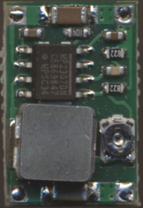
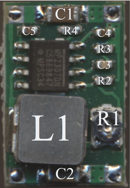
Reverse engineering Mini360 module
Bron: https://johndoe31415.github.io/mp2307calc/
This is a reverse-engineered component placement diagram from one of the common Mini-360 switch mode power supply circuits. The software to calculate resistor values can be found here and the schematic PDF is here. Essentially, it’s the “typical application” copied 1:1 — I’ve labled the components as they are in the datasheet, so that it’s easy to find your way around there.
Schematic:

Note that there are deliberately underpowered, broken Mini-360 circuits in circulation. These will have horrible efficiency and be a general pain-in-the-butt. Here’s what was different in my “broken” version compared to the version I got that was good:
- C1, C2 is 6.8µF instead of 10µF
- L1 is 2.2 µH instead of 10µH
This will lead to regulator instability and general, horrible performance (40% efficiency and worse). Note that even the ones that are “properly” working have some deficiencies:
- C2 is supposed to be 20µF, but is only 10µF
- Bootstrapping capacitor C5 should be in the range 100nF – 1µF (see datasheet pg. 10) — only 10nF in circuit
- Extenal bootstrapping diode (e.g., 1N4148) is said to improve performance (see datasheet pg. 10) — not present in circuit
- External schottky diode (e.g., MBRS130) is said to improve performance (see datasheet pg. 7) — not present in circuit
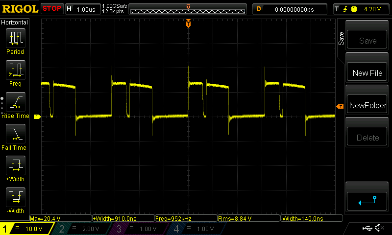
To figure out if you’re suffering from regulator instability, the easiest way is to directly measure at the inductor (side facing out). If everything is great, you’ll see something like this:
If you’re experiencing intermittent regulator instabilities, you’ll see something like this (if you’re lucky):

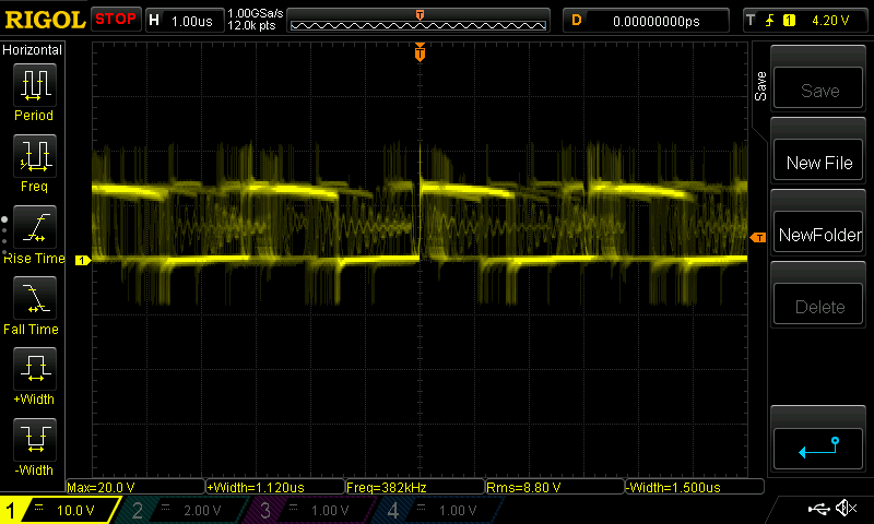
If it’s even worse, you might see something like this:
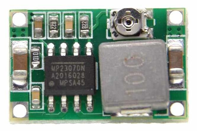
Here’s the hardware: