EEZY Bot ARM – Bouwinstructies
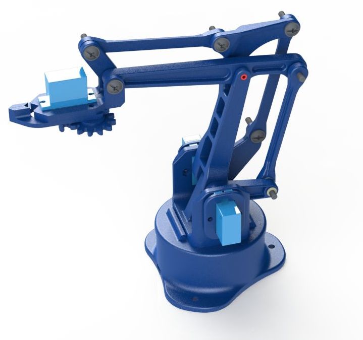
Bouwpakket project
EEZY Bot ARM
BOUWINSTRUCTIES
Informatie (ENG):
Part list
| count | part |
|---|---|
| 1 | EBA_01.00.001.STL |
| 1 | EBA_01.00.002_vertical_drive_arm.STL |
| 3 | EBA_01.00.003_link.STL |
| 1 | EBA_01.00.004_forward_drive_arm.STL |
| 1 | EBA_01.00.005_horizontal_arm.STL |
| 1 | EBA_01.00.006_triangular_link.STL |
| 2 | EBA_01.00.009_servo_plate.STL |
| 1 | EBA_01.00.010_basement.STL |
| 1 | EBA_01.00.011_round_plate.STL |
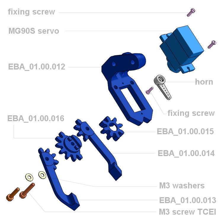
| 1 | EBA_01.00.012_R01_claw_support.STL |
| 1 | EBA_01.00.013_R01_right_finger.STL |
| 1 | EBA_01.00.014_R01_left_finger.STL |
| 1 | EBA_01.00.015_drive_gear.STL |
| 1 | EBA_01.00.016_R01_driven_gear.STL |
| 1 | EBA_01.00.017_R01_ramp.STL (optional) |
| 1 | EBA_01.00.018_maestro_holder.STL (optional) |
| 1 | EBA_01.00.019_ball.STL (optional) |
| 3 | Tower Pro SG90/MG90S servos |
| 1 | Tower Pro SG90 servo (gripper) + 1 optional for the loop ramp |
| 7 | M4 self locking nuts |
| 15 | M4 washers |
| 7 | M3 nuts |
| 1 | M3 x 30 screw |
| 2 | M3 washers |
| 4 | M3 x 12 hex screw |
| 2 | M3 x 12 TCEI screw |
| 2 | M3 x 20 TCEI screw |
| 5 | M4 x 20 round hed hex recess screw |
| 1 | brass pipe 4 x 3 x 22 + n°1 4 x 3 x 26 |
Electronics
The Arm can be driven in several different ways : sketches, potentiometers, joystick, WII nunchuck …. after several trials I found very “easy” to use a controller from Pololu: Mini Maestro USB Servo Controller. You can attach up to 6 – 12 – 24 servos depend of the controller type. It is provided with a free configuration and control program for Windows and Linux that give you the power to drive the servo in manual moving slides; in the mean time you are able to set the values of speed and acceleration for any singular item. You can also build sequences of servo movements and run scripts stored in the internal script memory that can be automatically played back without any computer or external microcontroller connected.
Stap 01
Nodig (mijn montage/bevindingen): 2x M4x15
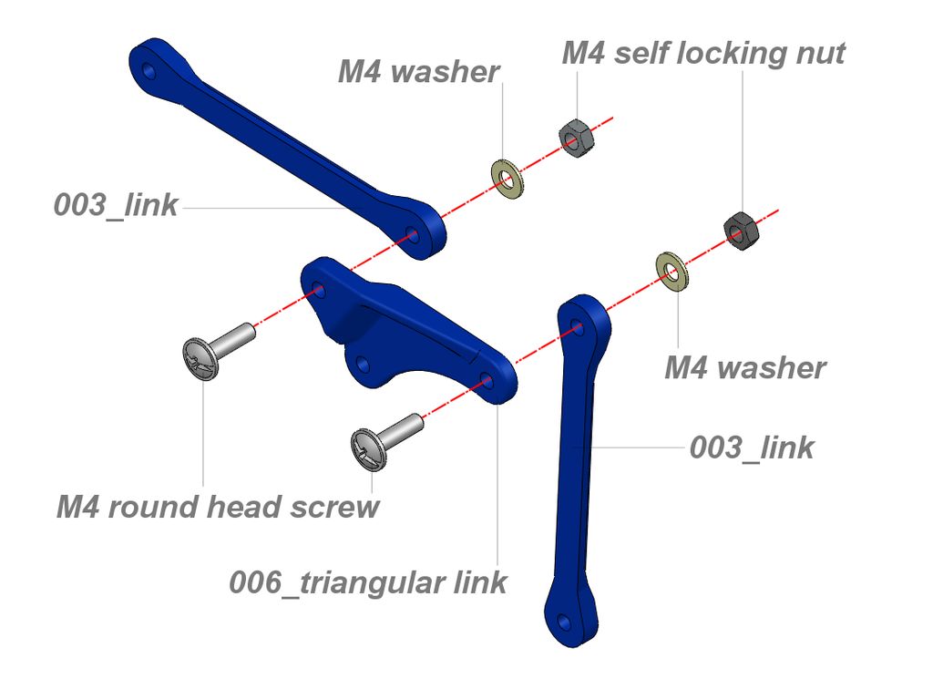
Connect two link arms (003) to the Triangular link (006).
Keep the M4 round heads screws to the inner side like shown on image and selflocking nuts to the outer side.
IMPORTANT
I design all the holes of joints quite exact to allow to make them more precise using a drill bit
The nuts are to be tightened till the locking of the joint, then consequently you must loose them until you obtain a smooth movement with the lower clearance between components. This rule is valid and is to be applied also for the following joint that involve use of self locking nuts.
Stap 02
Nodig (mijn montage/bevindingen): 2x M4x20
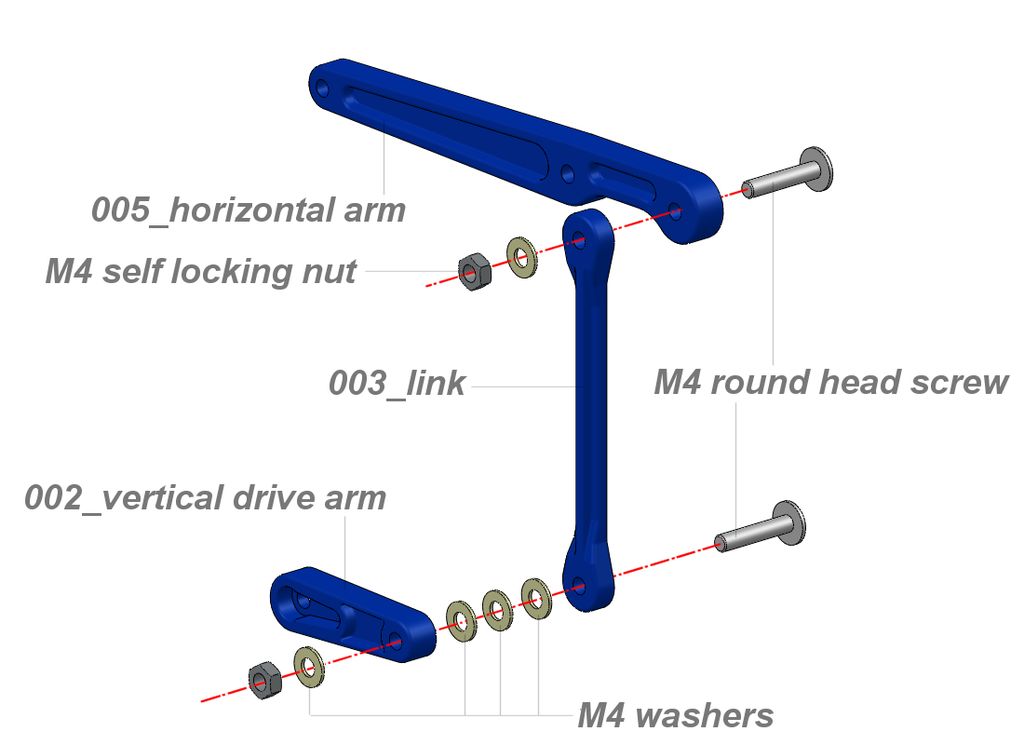
Connect link (003) to the rear joint of the horizontal arm (005).
The lower part of the link (003) is to be connected with the vertical drive arm (002) as shown.
Between the two links interpose three M4 washer, this to better align them with the vertical arm
Keep the M4 round heads screws to the inner side and self locking nuts outside
Stap 03
Nodig (mijn montage/bevindingen): 1x M4x30
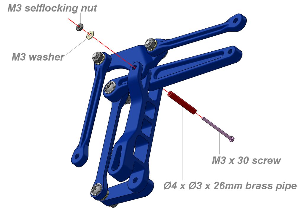
Connect now the two preassembled links to the forward drive arm (004).
Punt in position horizontal arm (005) and triangular link (006) aligned with the upper connection of the forward drive arm (004). Insert the Ø4 mm brass pipe crossing all the parts and fix it with the M3x30 screw, locked by the nut on the other side.
Verify the freedom of movement and If everything is ok, proceed to the next step.
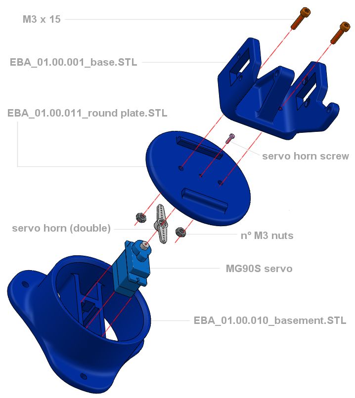
Base assembly
Stap 04
Nodig (mijn montage/bevindingen): 2x M3x12
Zie onder voor detail
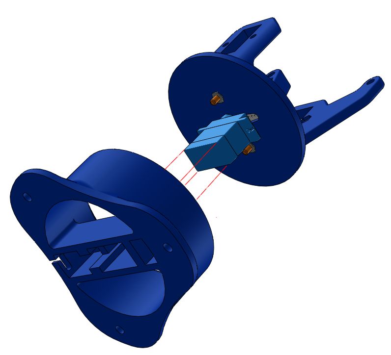
Stap 05
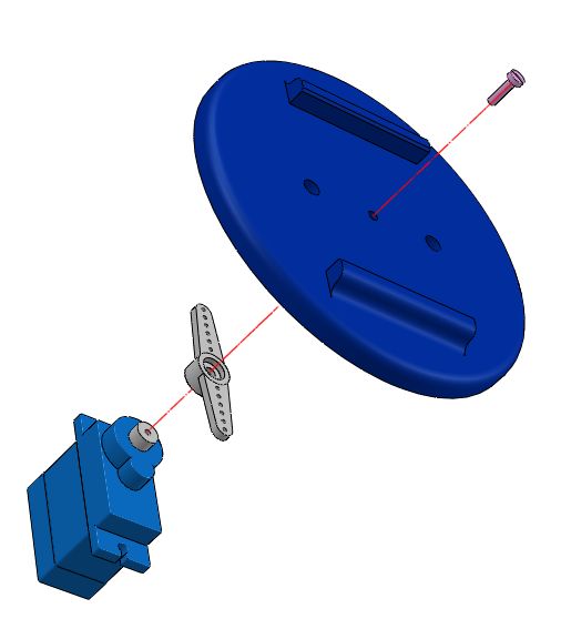
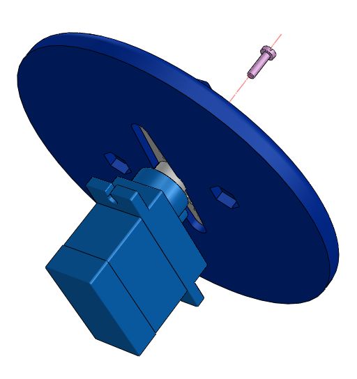
Be sure that the servo is in the neutral position than install the double arm horn on the splined shaft keeping the arms parallel to the servo body
Insert the horn inside the housing below the round plate and fix the servo to the plate using one of the two long screw supplied with the servo (the small one in too short due to the thickness of round plate)
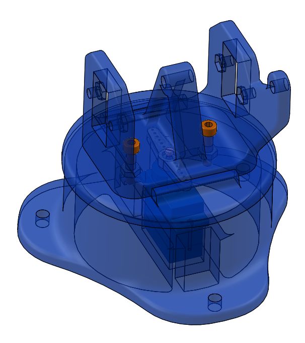
Stap 06
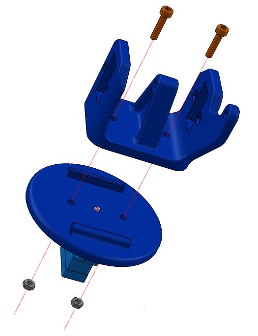
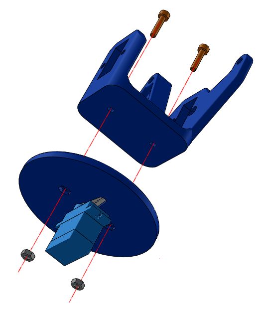
Put in position the base between the two shoulder on the plate and attach together using the two M3 screws and nuts. There two hexagonal housing below, so nuts will be kept in position during tightening
Stap 07
Put in position the base between the two shoulder on the plate and attach together using the two M3 screws and nuts. There two hexagonal housing below, so nuts will be kept in position during tightening
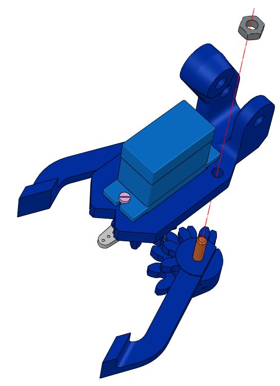
Gripper assembly
Stap 08
Stap 09
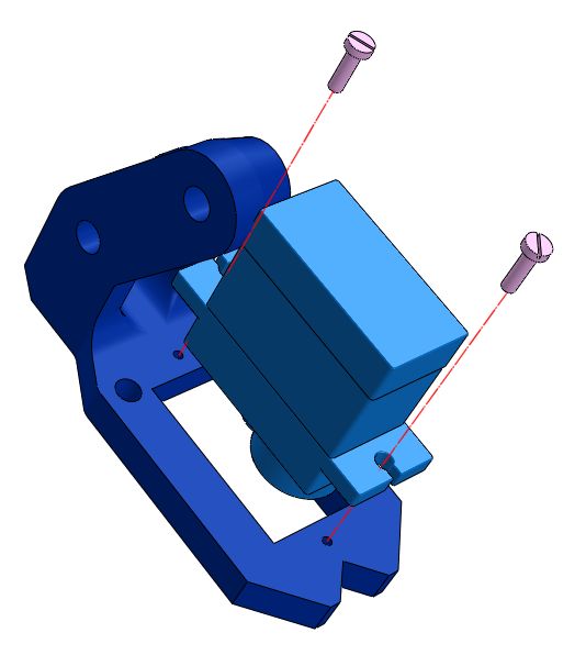
Attach the servo to the claw support using the two fixing screws supplied with the servo
Keep the output shaft forward
Stap 10

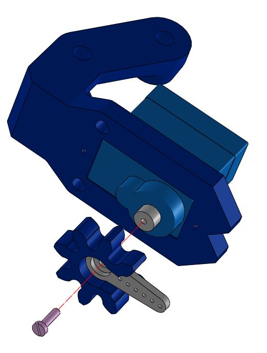
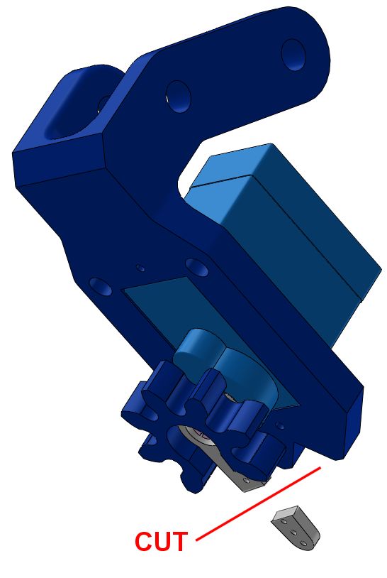
Insert the horn in the driven gear then attach the horn at the servo shaft using the supplied screw
The horn has to be aligned forward with the servo in neutral position. Cut the exceeding part of the horn from gear using a cutter
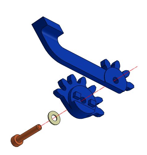
Stap 11
Nodig (mijn montage/bevindingen): M3x12
Insert an M3 screw in the central hole connect it to the claw support then tight the self locking nut checking the freedom of movement
Stap 12
Nodig (mijn montage/bevindingen): M3x20
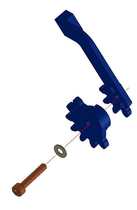
Insert the two pin of the driven gear into the dedicated holes on the left finger The driven gear has also a shoulder that has to be aligned with the lateral side of the finger. If you find difficulties coupling them, reduce interference using a file.
Once coupled insert an M3 screw in the central hole and attach the finger to the claw support
Now the gripper is ready to be installed on the horizontal arm of the EEzybot
Verify freedom of movement of the gripper manually or using a servo tester
Final assembly
Stap 13
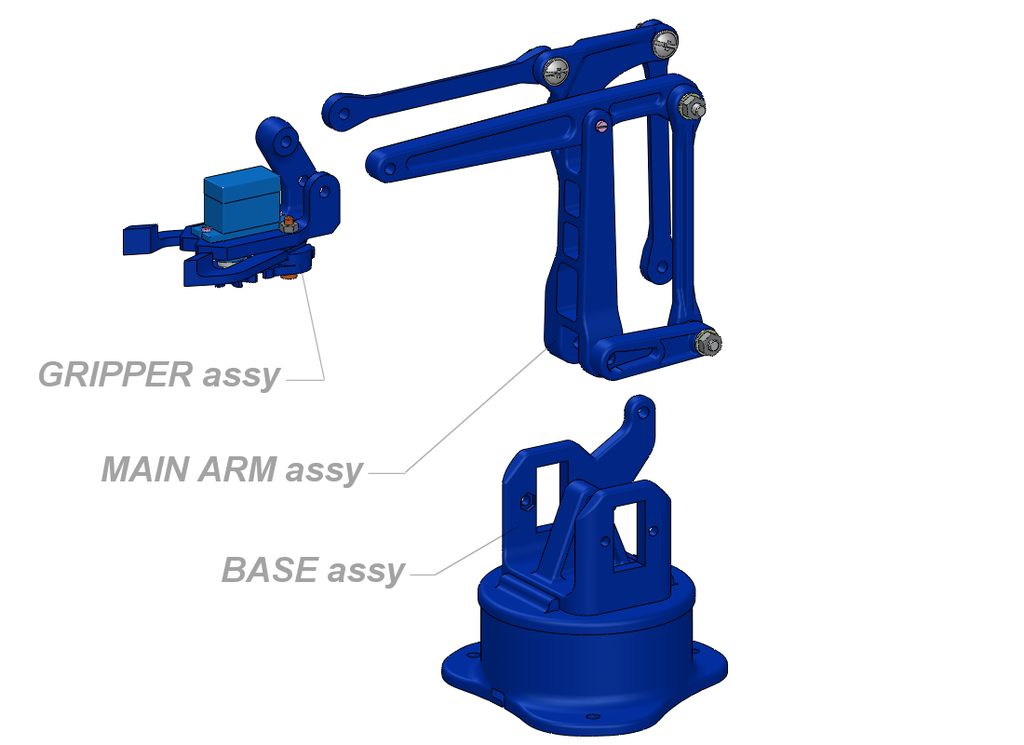
Now we have the three main sub assembly ready to be connected each other.
Next step we will join the base with the main arms
Stap 14
Nodig (mijn montage/bevindingen): M4x20 verzonken schroef
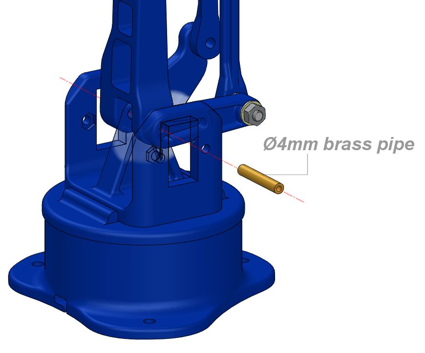
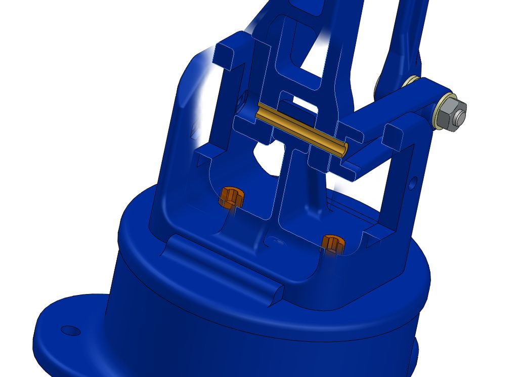
To join the base with the main arms align the axis of the parts and insert from one side the brass pipe 24mm long.
Also the short arm of the servo that drive the vertical movement has to be supported by the brass pipe as shown on the pictures.
Check the freedom of movement
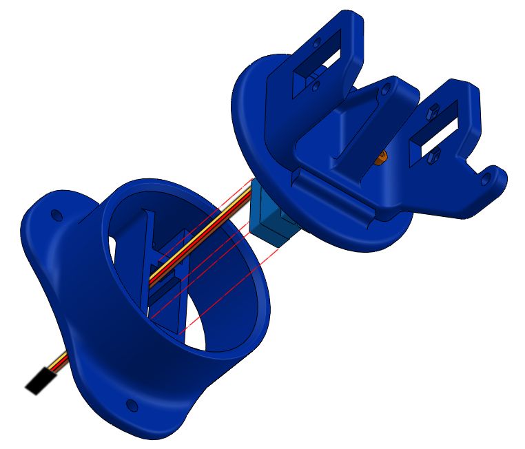
Stap 15
Nodig (mijn montage/bevindingen): 2x M3x15
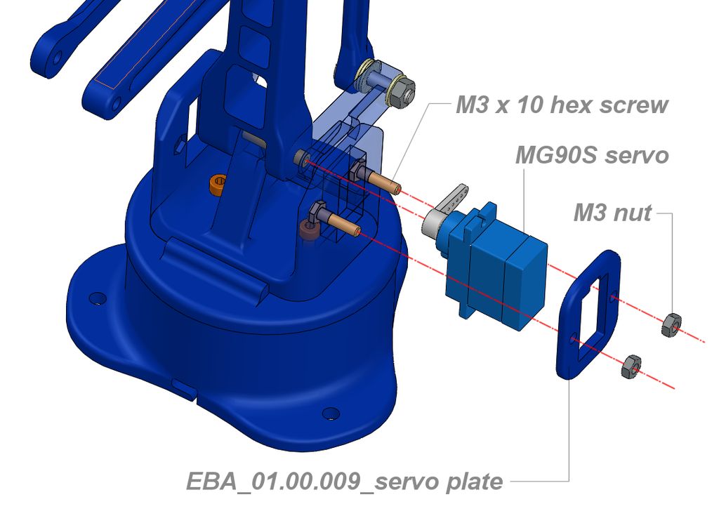
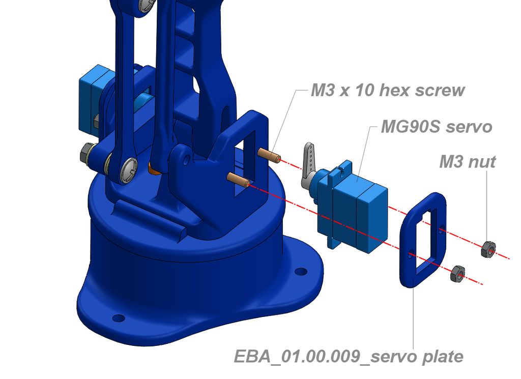
Is time now to install the servo that drive the vertical movement of the arm. Put in the dedicate receptacles two M3x10 hex screw. The servo has to be in the neutral position with the horn at 90 degrees on the right side with the press plate (009) installed (Make the wiring pass through the dedicated enlargment).
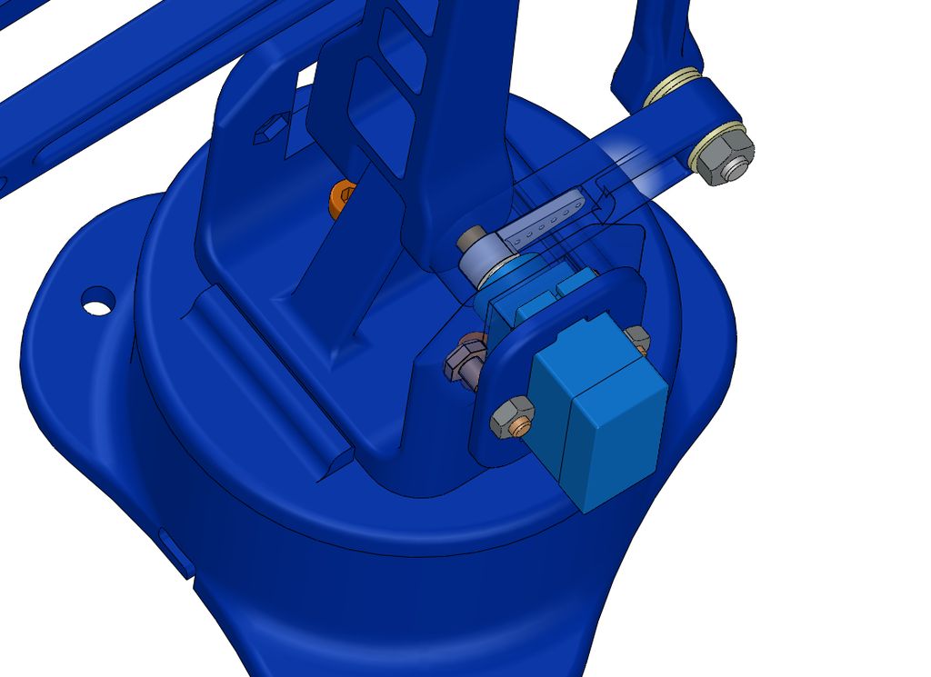
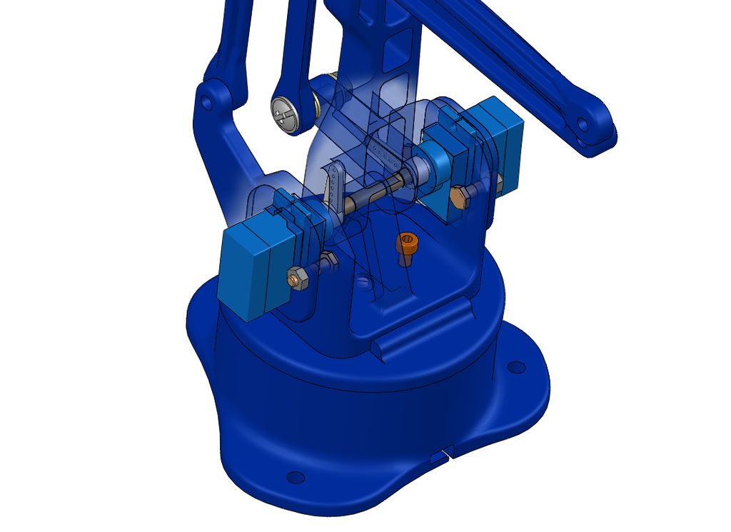
Introduce the servo angled in the square seat on the base plate and slide the horn in the shaped housing of the arm that drives the vertical movement. Fix the press plate against the servo using two M3 nuts
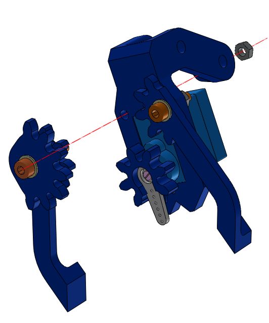
Stap 16
Nodig (mijn montage/bevindingen): 2x M3x15
Is time now to install the servo that drive the vertical movement of the arm. Put in the dedicate receptacles two M3x10 hex screw. The servo has to be in the neutral position with the horn at 90 degrees on the right side with the press plate (009) installed (Make the wiring pass through the dedicated enlargment).
Introduce the servo angled in the square seat on the base plate and slide the horn in the shaped housing of the arm that drives the vertical movement. Fixt the press plate against the servo using two M3 nuts
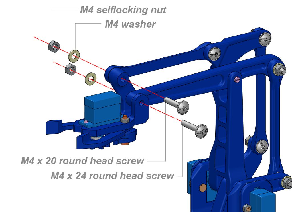
Stap 17
Nodig (mijn montage/bevindingen): M4x20
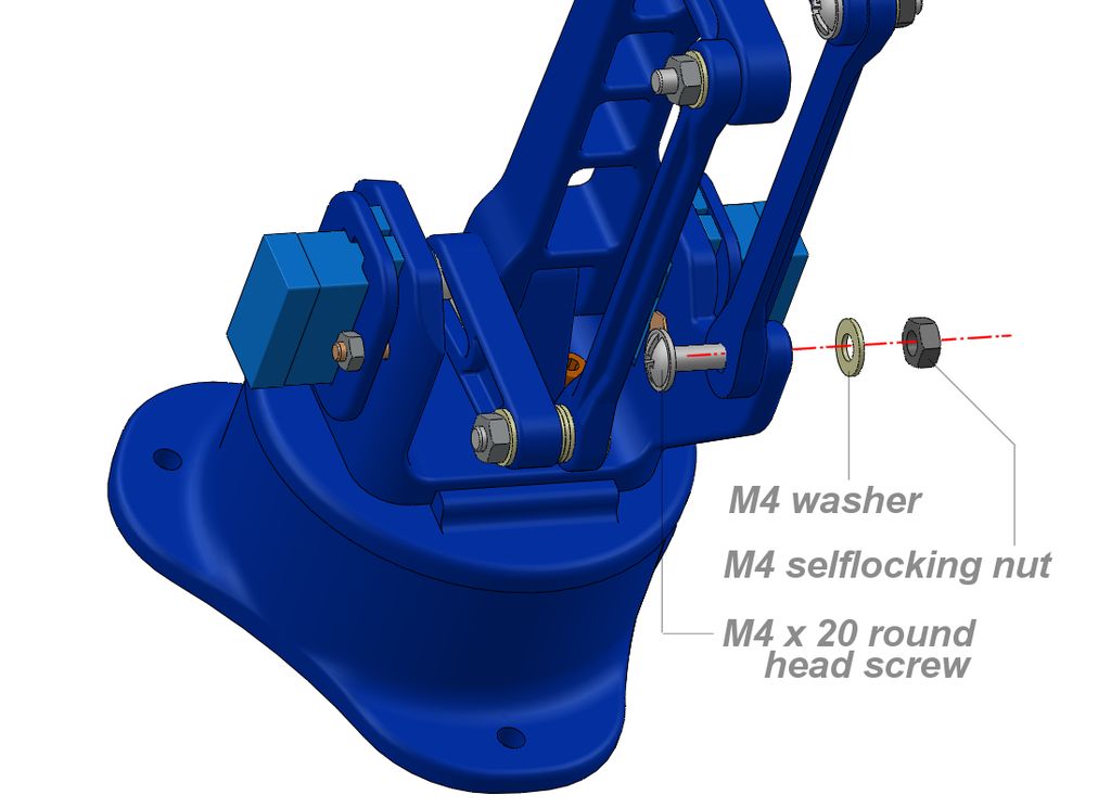
attach the latest link to the fixed arm on the rear side of the base using a M4x20 a washer and a selflocking nut
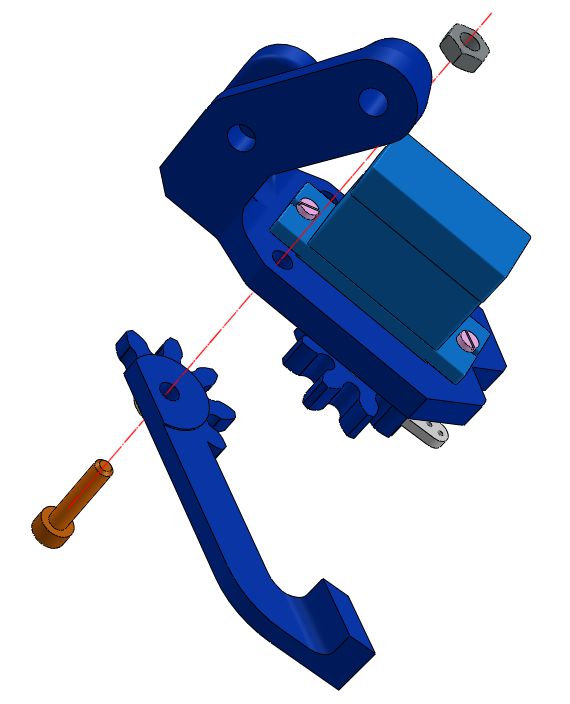
Attaching the gripper
Stap 18
The last assembly step is to join the gripper to the horizontal arm as shown on the picture.
At the end of the last step the ARM is ready to work.
As an optional, In the 3D model downodable from Thinghiverse, I add a round ramp that allow to easy obtain a loop test with a ball (3D printed, obviously!). In the video linked on first page is shown what I mean.
To make this tool to work you have to attach another servo (cheap SG90) to the end of the ramp. I keep th ramp center at a distance of about 180mm from the base vertical axis.
There is also a 3D model of a support dedicated to the Pololu USB servo.
The way to drive the servo are several. I tried them pretty all. To explain it will take to much and this instructable is big enough ….. probably I’ll make a new instructables dedicated, If I get time. Anyway if you want to explore there are quite enough material around the web.
As told at the beginning, I found very easy using a Pololu USB servo Mini Maestro, it is not very cheap but solve a lot of problems. You have to install drivers, a software and when connected to usb you’re are immediately able to drive the servos choosing their speed and acceleration also. You can store the servo position to a sequence and when ready it can be played once or in a loop. Can also be stored in the internal script memory and it can be automatically played without computer connected.