ESP8266 WiFi – Adapters
![]()
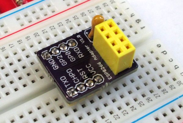
ESP-01 Adapter
Sommige modules zoals de ESP-01 kunnen niet op een breadbord geplaatst worden ivm de pin lay-out van de module (kortsluiting), daarvoor zijn er bestaande adapters te verkrijgen:
Maar je kan deze uiteraard ook zelf maken (ENG):
Using the ESP8266 module with a breadboard
I ordered a module which is called the 01 version, which has a 2*4 connector (not breadboard friendly…) and a wifi antenna printed on the PCB. My thinking was that this version probably doesn’t have much power, but it’s the cheapest option and all the components (especially the antenna) are integrated on the tiny PCB, so it would be ideal for experiments.
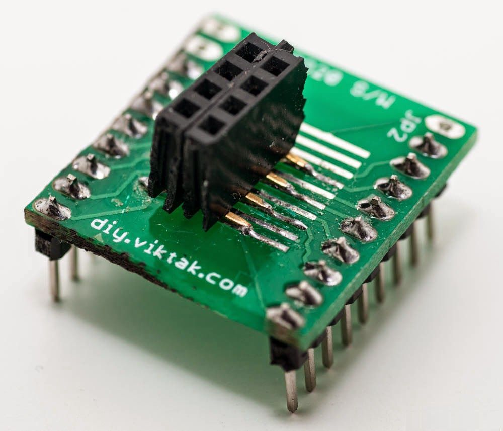
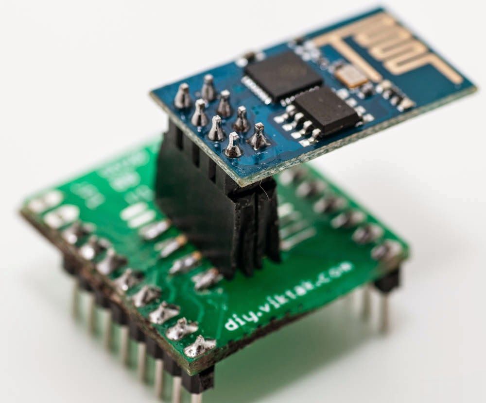
As I did not want the module to be floating freely in the air/on my desk, I needed a way to adapt it to a breadboard. I remembered I had a few SOIC-DIP adapter PCBs left over, so I decided to use one of them for this purpose.
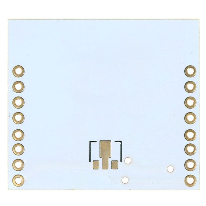
ESP-07 – ESP-08 – ESP-12 adapter
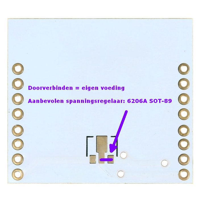
Er zijn een aantal ESP8622 modules welke niet een “standaard” 2,54mm pitch hebben en daarom niet compatibel zijn met een breadboard, daar voor zijn ook adapters ontwikkeld, zoals deze:
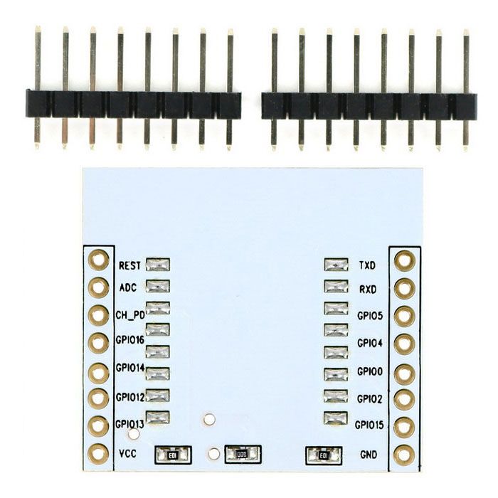
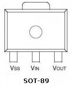
Echter heeft deze adapter nog een spanningsregelaar van 3.3v nodig, de 6206A in een SOT-89 uitvoering (wordt meestal niet bijgeleverd)
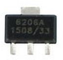
of je kan 2 pinnen “doorsolderen” en een eigen 3.3v voeding gebruiken!
Je kan ze ook eenvoudig zelf een adapter in elkaar zetten:
Informatie (ENG)
I’ve ordered the Esp8266 in the form factor or model “03” which has no standard 2,54mm pin headers. If you want to use it with a breadboard, you’ll need to solder an adapter.
Currently there are 12 different form factors of the Esp8266 available (e.g. here. Not counting sets and development kits). Each version has its own advantages and disadvantages in regards to features, pinouts, form and size. To be most flexible I’ve ordered model “03”, as also posted here as it has the highest number of I/O pins.
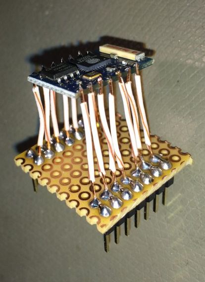
The small size results in incompatibility to the standard 2,54 pin header spacing. To fix this I soldered it on a PCB with normal pin headers below. I was generous with the size of the PCB. It’s possible to squeeze it to 4×7 holes. But I’ve never done something like that before and didn’t know how good the wires could be soldered.
Here are the steps:
- Remove 1mm isolation from the side which should be soldered to the module
- Remove 2cm isolation of the other side
- Add a small portion of solder to the notches at the board
- Heat up each notch and put the wire into the liquid solder
- Repeat step 1-4 for each pin
- Stick module with wires to the PCB, copper side facing to the module. Be careful not to break off the wire from the module
- Solder wires to PCB
- Solder pin headers to PCB and connect each pin with solder to the wire
- Done.
Bronnen:
sebastian-hodapp.de
diy.viktak.com