ESP8266 WiFi – Algemene informatie
![]()
Wat is de ESP8266 chip?
Deze chip is de WiFi-oplossing voor uw microcontroller en pic projecten. De ESP8266 chip is nu beschikbaar in een brede schaal van module en formaten. De populariteit van de WiFi-SoC UART Serial module is gegroeid in populariteit sinds haar oprichting.
Informatie (ENG):
ESP8266 is a complete and self-contained Wi-Fi network solutions that can carry software applications, or through Another application processor uninstall all Wi-Fi networking capabilities. ESP8266 when the device is mounted and as the only application of the application processor, the flash memory can be started directly from an external Move. Built-in cache memory will help improve system performance and reduce memory requirements. Another situation is when wireless Internet access assume the task of Wi-Fi adapter, you can add it to any microcontroller-based design, the connection is simple, just by SPI / SDIO interface or central processor AHB bridge interface. Processing and storage capacity on ESP8266 powerful piece, it can be integrated via GPIO ports sensors and other applications specific equipment to achieve the lowest early in the development and operation of at least occupy system resources. The ESP8266 highly integrated chip, including antenna switch balun, power management converter, so with minimal external circuitry, and includes front-end module, including the entire solution designed to minimize the space occupied by PCB. The system is equipped with ESP8266 manifested leading features are: energy saving VoIP quickly switch between the sleep / wake patterns, with low-power operation adaptive radio bias, front-end signal processing functions, troubleshooting and radio systems coexist characteristics eliminate cellular / Bluetooth / DDR / LVDS / LCD interference.
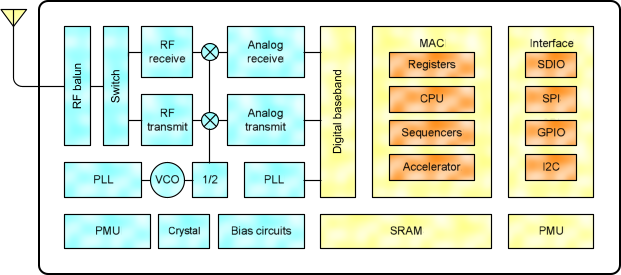
Wat zit er allemaal in de chip?
Hieronder een klein overzichtje wat er zich allemaal onder de motorkap plaatsvind:
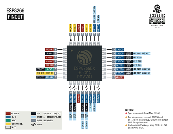
Pinout v/d Chip
De ESP8266 chip biedt het volgende:
- 802.11 b / g / n-protocol
- Wi-Fi Direct (P2P), soft-AP
- Geïntegreerde TCP / IP protocol stack
- Geïntegreerde transmissiestandschakelaar, balun, LNA, eindversterker en matching netwerk
- Geïntegreerde PLL, toezichthouders en power management units
- + 20.5dBm uitgangsvermogen 802.11b-modus
- Ondersteunt diversiteit antenne
- Uitschakelen lekstroom van <10uA
- Geïntegreerde low power 32-bit MCU
- SDIO 2.0, SPI, UART
- STBC, 1 × 1 MIMO, 2 × 1 MIMO
- A-MPDU & A-MSDU aggregatie & 0.4μs guard interval
- Word wakker en doorgeven pakketten in <22ms
- Standby-verbruik van <1.0mW (DTIM3)
Deze chip is te vinden is diverse module uitvoeringen genaamd “ESP-XX”
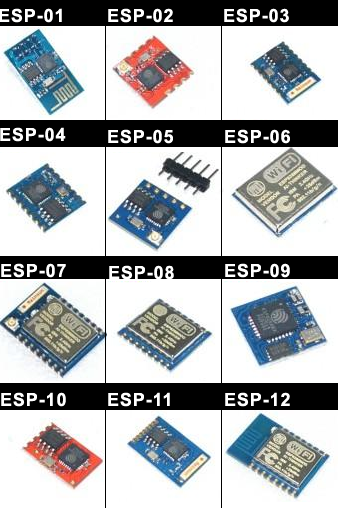
De verschillen in de modules:
ESP-01
This is probably one of the most popular modules, although it is by far not the most convenient one. With its small form factor (24.75mm x 14.5mm) it fits nicely into any enclosure. Two GPIO pins are led out and can be used to control periphery. With proper wiring and a serial-to-usb adapter you can also easily flash alternatives firmwares on it. By default it comes with one of the different versions of the AT firmware which allows you to use it in combination with an Arduino. One of the biggest problems of this module is the placement of the pin posts which makes it impossible to plug it directly into a bread board for prototyping: the two rows of posts are so close to each other that you would get a short-cirtcuit. However you can still use this module on a breadboard: either build a bread-board adapter or use female-to-male dupont wires to wire the module to your bread-board.
This module is very simple and has one purpose only: use it as mini wifi shield together with your Arduino or similar micro controller. There are different versions available: a four pin version that only has 3.3V, GND, RX and TX. Over the later ones you talk with your Arduino. Another version has an additional reset pin which allows you to manually or programatically reset the module.
ESP-12
This module allows you to access many features of the ESP8266: 11 GPIO pins, one analog-to-digital converter (ADC) with a 10 bit resolution. It also lets you easily configure deep-sleep mode which (according to this source) lets you run the module for 3 years on two AA batteries. With one drawback: it is not breadboard friendly at all. As for the modules previously described here the antenna is a track on the PCB which delivers good results for Wifi sensitivity.
But to use it for prototyping you´ll have to build something around the module. You can order these breadboard adapters or build one yourself, like my colleague Andi did:
| Board ID | pins | pitch | form factor | LEDs | Antenna | Ant.Socket | Shielded | dimensions mm |
|---|---|---|---|---|---|---|---|---|
| ESP-01 | 8 | .1“ | 2×4 DIL | Yes | Etched-on PCB | No | No | 14.3 x 24.8 |
| ESP-02 | 8 | .1” | 2×4 notch | No? | None | Yes | No | 14.2 x 14.2 |
| ESP-03 | 14 | 2mm | 2×7 notch | No | Ceramic | No | No | 17.3 x 12.1 |
| ESP-04 | 14 | 2mm | 2×4 notch | No? | None | No | No | 14.7 x 12.1 |
| ESP-05 | 5 | .1“ | 1×5 SIL | No | None | Yes | No | 14.2 x 14.2 |
| ESP-06 | 12+GND | misc | 4×3 dice | No | None | No | Yes | ? |
| ESP-07 | 16 | 2mm | 2×8 pinhole | Yes | Ceramic | Yes | Yes | 20.0 x 16.0 |
| ESP-08 | 14 | 2mm | 2×7 notch | No | None | No | Yes | 17.0 x 16.0 |
| ESP-09 | 12+GND | misc | 4×3 dice | No | None | No | No | 10.0 x 10.0 |
| ESP-10 | 5 | 2mmm? | 1×5 notch | No | None | No | No | 14.2 x 10.0 |
| ESP-11 | 8 | 1.27mm | 1×8 pinhole | No? | Ceramic | No | No | 17.3 x 12.1 |
| ESP-12 | 16 | 2mm | 2×8 notch | Yes | Etched-on PCB | No | Yes | 24.0 x 16.0 |
| ESP-12-E | 22 | 2mm | 2×8 notch | Yes | Etched-on PCB | No | Yes | 24.0 x 16.0 |
| ESP-13 | 18 | 1.5mm | 2×9 | ? | Etched-on PCB | No | Yes | ? x ? |
| WROOM-02 | 18 | 1.5mm | 2×9 | No | Etched on PCB | No | Yes | 20.0 x 18.0 |
| WT8266-S1 | 18 | 1.5mm | 3×6 | 1 | Etched on PCB | No | Yes | 15.0 x 18.6 |
Voeden en communiceren
Om direct te communiceren met de ESP8266 kunt je een standaard 3.3v FTDI USB naar TTL adapter/kabel gebruiken, maar de meeste USB adapters leveren niet genoeg stroom (mA) voor de module, daarvoor wordt aangeraden om een extra externe 3,3 V voeding te gebruiken zodat de module goed gevoed anders kunnen er onverwachtse complicaties voorkomen.
Een aantal tips om te voeden:
1. Zorg voor een aparte voeding voor de ESP die min. 215 mA kan leveren.
2. Zorg voor een goede ontkoppeling van de voeding doormiddel van een ker. C. van 100n + Flinke elco (>100uF) direct op de voedingsaansluitingen. Zoniet dan zul je zeer waarschijnlijk met spontane reboots te maken krijgen.
3. Let op dat ESP (ook de ingangen) max 3.6 Volt mogen hebben (liefst 3.3V).
4. Zorg dat de resetingang geen stoorpieken kan ontvangen.
Stroomverbruik (ENG)
The following data are based on a 3.3V power supply, ambient temperature 25C and use the internal regulator measured. [1] All measurements are made in the absence of the SAW filter, the antenna interface is completed. [2] all transmit data based on 90% duty cycle, continuous transmission mode in the measured
| Mode | Min | Typical | Max | Units |
|---|---|---|---|---|
| 802.11b, CCK 1Mbps, POUT=+19.5dBm | 215 | mA | ||
| 802.11b, CCK 11Mbps, POUT=+18.5dBm | 197 | mA | ||
| 802.11g, OFDM 54Mbps, POUT=+16dBm | 145 | mA | ||
| 802.11n, MCS7, POUT =+14dBm | 135 | mA | ||
| 802.11b, packet size of 1024 bytes, -80dBm | 60 | mA | ||
| 802.11b, packet size of 1024 bytes, -70dBm | 60 | mA | ||
| 802.11b, packet size of 1024 bytes, -65dBm | 62 | mA | ||
| Standby | 0.9 | uA | ||
| Deep sleep | 10 | mA | ||
| Saving mode DTIM 1 | 1.2 | mA | ||
| Saving mode DTIM 3 | 0.86 | mA | ||
| Shutdown | 0.5 | uA |
RF specifications
The following data is at room temperature, the voltage of 3.3V and 1.1V, respectively, when measured
| Description | Min | Typical | Max | Units |
|---|---|---|---|---|
| Input Frequency | 2412 | 2484 | MHz | |
| Input resistance | 50 | Ω | ||
| Input reflection | -10 | dB | ||
| At 72.2Mbps, PA output power | 14 | 15 | 16 | dBm |
| 11b mode, PA output power | 17.5 | 18.5 | 19.5 | dBm |
| Sensitivity | ||||
| CCK, 1Mbps  | -98 | dBm | ||
| CCK, 11Mbps  | -91 | dBm | ||
| 6Mbps (1/2 BPSK)  | -93 | dBm | ||
| 54Mbps (3/4 64-QAM)  | -75 | dBm | ||
| HT20, MCS7 (65Mbps, 72.2Mbps)   | -71 | dBm | ||
| Adjacent suppression | ||||
| OFDM, 6Mbps | 37 | dB | ||
| OFDM, 54Mbps | 21 | dB | ||
| HT20, MCS0 | 37 | dB | ||
| HT20, MCS7 | 20 | dB |
Power Management (ENG)
Chip can tune into the following states:
- off (OFF): CHIP_PD pin is in a low power state. RTC failure. All registers are emptied.
- deep sleep (DEEP_SLEEP): RTC open, other parts of the chip are closed. RTC internal recovery memory to save the basic WiFi connection information.
- sleep (SLEEP): Only RTC running. Crystal oscillator stops. Any part of the wake (MAC, host, RTC timer, external interrupt) will make the wake of the chip.
- Wake (WAKEUP): In this state, the system from a sleep state to start (PWR) status. Crystal oscillator and PLL are converted enabled state.
* on state (ON): High-speed clock can run, And sent to each clock control register is enabled Modules. Each module, including the CPU, including the implementation of relatively low-level clock gating. When the system works, you can WAITI instructions to turn off the CPU’s internal clock.
Frequenties (ENG)
According IEEE802.11bgn standard, RF transceiver supports the following channels:
| Channel | Freq. | Channel | Freq. |
|---|---|---|---|
| 1 | 2412 | 8 | 2447 |
| 2 | 2417 | 9 | 2452 |
| 3 | 2422 | 10 | 2457 |
| 4 | 2427 | 11 | 2462 |
| 5 | 2432 | 12 | 2467 |
| 6 | 2437 | 13 | 2472 |
| 7 | 2442 | 14 | 2484 |
Bronnen:
wiki.iteadstudio.com
nurdspace.nl
esp8266.com