ESP8266 WiFi – esp-link Firmware
![]()
![]()
This firmware connects an attached micro-controller to the internet using a ESP8266 Wifi module. It implements a number of features:
- transparent bridge between Wifi and serial, useful for debugging or inputting into a uC
- flash-programming attached Arduino/AVR microcontrollers, esp8266 modules, as well as LPC800-series and other ARM microcontrollers via Wifi
- built-in stk500v1 programmer for AVR uC’s with optiboot: program using HTTP upload of hex file
- outbound TCP (and thus HTTP) connections from the attached micro-controller to the internet
- outbound REST HTTP requests from the attached micro-controller to the internet, protocol based on espduino and compatible with tuanpmt/espduino
The firmware includes a tiny HTTP server based on esphttpd with a simple web interface, many thanks to Jeroen Domburg for making it available!
Many thanks to https://github.com/brunnels for contributions in particular around the espduino functionality. Thank you also tohttps://github.com/susisstrolch and https://github.com/bc547 for additional contributions!
Esp-link uses
The simplest use of esp-link is as a transparent serial to wifi bridge. You can flash an attached uC over wifi and you can watch the uC’s serial debug output by connecting to port 23 or looking at the uC Console web page.
The next level is to use the outbound connectivity of esp-link in the uC code. For example, the uC can use REST requests to services like thingspeak.com to send sensor values that then get stored and plotted by the external service. The uC can also use REST requests to retrieve simple configuration information or push other forms of notifications. (MQTT functionality is forthcoming.)
An additional option is to add code to esp-link to customize it and put all the communication code into esp-link and only keep simple sensor/actuator control in the attached uC. In this mode the attached uC sends custom commands to esp-link with sensor/acturator info and registers a set of callbacks with esp-link that control sensors/actuators. This way, custom commands in esp-link can receive MQTT messages, make simple callbacks into the uC to get sensor values or change actuators, and then respond back with MQTT. The way this is architected is that the attached uC registers callbacks at start-up such that the code in the esp doesn’t need to know which exact sensors/actuators the attached uC has, it learns that through the initial callback registration.
Hardware info
This firmware is designed for any esp8266 module. The recommended connections for an esp-01 module are:
- URXD: connect to TX of microcontroller
- UTXD: connect to RX of microcontroller
- GPIO0: connect to RESET of microcontroller
- GPIO2: optionally connect green LED to 3.3V (indicates wifi status)
The recommended connections for an esp-12 module are:
- URXD: connect to TX of microcontroller
- UTXD: connect to RX of microcontroller
- GPIO12: connect to RESET of microcontroller
- GPIO13: connect to ISP of LPC/ARM microcontroller or to GPIO0 of esp8266 being programmed (not used with Arduino/AVR)
- GPIO0: optionally connect green “conn” LED to 3.3V (indicates wifi status)
- GPIO2: optionally connect yellow “ser” LED to 3.3V (indicates serial activity)
If your application has problems with the boot message that is output at ~74600 baud by the ROM at boot time you can connect an esp-12 module as follows and choose the “swap_uart” pin assignment in the esp-link web interface:
- GPIO13: connect to TX of microcontroller
- GPIO15: connect to RX of microcontroller
- GPIO1/UTXD: connect to RESET of microcontroller
- GPIO3/URXD: connect to ISP of LPC/ARM microcontroller or to GPIO0 of esp8266 being programmed (not used with Arduino/AVR)
- GPIO0: optionally connect green “conn” LED to 3.3V (indicates wifi status)
- GPIO2: optionally connect yellow “ser” LED to 3.3V (indicates serial activity)
If you are using an FTDI connector, GPIO12 goes to DTR and GPIO13 goes to CTS (or vice-versa, I’ve seen both used, sigh).
The GPIO pin assignments can be changed dynamically in the web UI and are saved in flash.
Initial flashing
If you want to simply flash a pre-built firmware binary, you can download the latest release and use your favorite ESP8266 flashing tool to flash the bootloader, the firmware, and blank settings. Detailed instructions are provided in the release notes.
Important: the firmware adapts automatically to the size of the flash chip using information stored in the boot sector (address 0). This is the standard way that the esp8266 SDK detects the flash size. What this means is that you need to set this properly when you flash the bootloader. If you use esptool.py you can do it using the -ff and -fs options.
Wifi configuration overview
For proper operation the end state that esp-link needs to arrive at is to have it join your pre-existing wifi network as a pure station. However, in order to get there esp-link will start out as an access point and you’ll have to join its network to configure it. The short version is:
- esp-link creates a wifi access point with an SSID of the form
ESP_012ABC(some modules use a different SSID form, such asai-thinker-012ABC) - you join your laptop or phone to esp-link’s network as a station and you configure esp-link wifi with your network info by pointing your browser at http://192.168.4.1/
- you set a hostname for esp-link on the “home” page, or leave the default (“esp-link”)
- esp-link starts to connect to your network while continuing to also be an access point (“AP+STA”), the esp-link may show up with a
${hostname}.localhostname (depends on your DHCP/DNS config) - esp-link succeeds in connecting and shuts down its own access point after 15 seconds, you reconnect your laptop/phone to your normal network and access esp-link via its hostname or IP address
LED indicators
Assuming appropriate hardware attached to GPIO pins, the green “conn” LED will show the wifi status as follows:
- Very short flash once a second: not connected to a network and running as AP+STA, i.e. trying to connect to the configured network
- Very short flash once every two seconds: not connected to a network and running as AP-only
- Even on/off at 1HZ: connected to the configured network but no IP address (waiting on DHCP)
- Steady on with very short off every 3 seconds: connected to the configured network with an IP address (esp-link shuts down its AP after 60 seconds)
The yellow “ser” LED will blink briefly every time serial data is sent or received by the esp-link.
Wifi configuration details
After you have serially flashed the module it will create a wifi access point (AP) with an SSID of the form ESP_012ABC where 012ABC is a piece of the module’s MAC address. Using a laptop, phone, or tablet connect to this SSID and then open a browser pointed at http://192.168.4.1/, you should then see the esp-link web site.
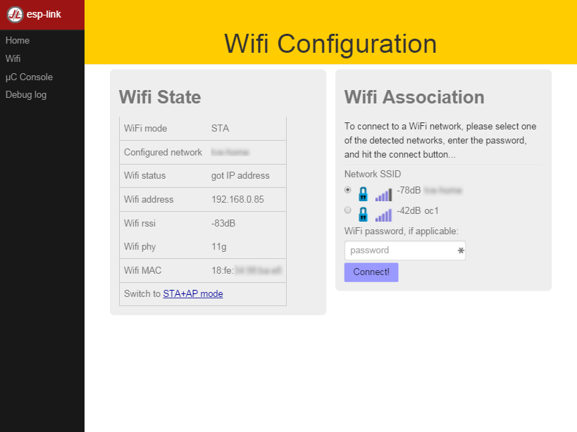
Now configure the wifi. The desired configuration is for the esp-link to be a station on your local wifi network so you can communicate with it from all your computers.
To make this happen, navigate to the wifi page and you should see the esp-link scan for available networks. You should then see a list of detected networks on the web page and you can select yours. Enter a password if your network is secure (highly recommended…) and hit the connect button.
You should now see that the esp-link has connected to your network and it should show you its IP address. Write it down. You will then have to switch your laptop, phone, or tablet back to your network and then you can connect to the esp-link’s IP address or, depending on your network’s DHCP/DNS config you may be able to go to http://esp-link.local
At this point the esp-link will have switched to STA mode and be just a station on your wifi network. These settings are stored in flash and thereby remembered through resets and power cycles. They are also remembered when you flash new firmware. Only flashing blank.bin via the serial port as indicated above will reset the wifi settings.
There is a fail-safe, which is that after a reset or a configuration change, if the esp-link cannot connect to your network it will revert back to AP+STA mode after 15 seconds and thus both present its ESP_012ABC-style network and continue trying to reconnect to the requested network. You can then connect to the esp-link’s AP and reconfigure the station part.
One open issue (#28) is that esp-link cannot always display the IP address it is getting to the browser used to configure the ssid/password info. The problem is that the initial STA+AP mode may use channel 1 and you configure it to connect to an AP on channel 6. This requires the ESP8266’s AP to also switch to channel 6 disconnecting you in the meantime.
Hostname, description, DHCP, mDNS
You can set a hostname on the “home” page, this should be just the hostname and not a domain name, i.e., something like “test-module-1” and not “test-module-1.mydomain.com”. This has a number of effects:
- you will see the first 12 chars of the hostname in the menu bar (top left of the page) so if you have multiple modules you can distinguish them visually
- esp-link will use the hostname in its DHCP request, which allows you to identify the module’s MAC and IP addresses in your DHCP server (typ. your wifi router). In addition, some DHCP servers will inject these names into the local DNS cache so you can use URLs like
hostname.local. - someday, esp-link will inject the hostname into mDNS (multicast DNS, bonjour, etc…) so URLs of the form
hostname.localwork for everyone (as of v2.1.beta5 mDNS is disabled due to reliability issues with it)
You can also enter a description of up to 128 characters on the home page (bottom right). This allows you to leave a memo for yourself, such as “installed in basement to control the heating system”. This descritpion is not used anywhere else.
Troubleshooting
- verify that you have sufficient power, borderline power can cause the esp module to seemingly function until it tries to transmit and the power rail collapses
- if you just cannot flash your esp8266 module (some people call it the zombie mode) make sure you have gpio0 and gpio15 pulled to gnd with a 1K resistor, gpio2 tied to 3.3V with 1K resistor, and RX/TX connected without anything in series. If you need to level shift the signal going into the esp8266’s RX use a 1K resistor. Use 115200 baud in the flasher. (For a permanent set-up I would use higher resistor values but when nothing seems to work these are the ones I try.)
- if the flashing succeeded, check the “conn” LED to see which mode esp-link is in (see LED info above)
- reset or power-cycle the esp-link to force it to become an access-point if it can’t connect to your network within 15-20 seconds
- if the LED says that esp-link is on your network but you can’t get to it, make sure your laptop is on the same network (and no longer on the esp’s network)
- if you do not know the esp-link’s IP address on your network, try
esp-link.local, try to find the lease in your DHCP server; if all fails, you may have to turn off your access point (or walk far enough away) and reset/power-cycle esp-link, it will then fail to connect and start its own AP after 15-20 seconds
Building the firmware
The firmware has been built using the esp-open-sdk on a Linux system. Create an esp8266 directory, install the esp-open-sdk into a sub-directory. Download the Espressif SDK (use the version mentioned in the release notes) from their download forum and also expand it into a sub-directory. Then clone the esp-link repository into a third sub-directory. This way the relative paths in the Makefile will work. If you choose a different directory structure look at the Makefile for the appropriate environment variables to define.
In order to OTA-update the esp8266 you should export ESP_HOSTNAME=... with the hostname or IP address of your module.
Now, build the code: make in the top-level of esp-link.
A few notes from others (I can’t fully verify these):
- You may need to install
zlib1g-devandpython-serial - Make sure you have the correct version of the esp_iot_sdk
- Make sure the paths at the beginning of the makefile are correct
- Make sure
esp-open-sdk/xtensa-lx106-elf/binis in the PATH set in the Makefile
It is possible to build esp-link on Windows, but it requires a gaggle of software to be installed:
- Install the unofficial sdk, mingw, SourceTree (gui git client), python 2.7, git cli, Java
- Use SourceTree to checkout under C:\espressif or wherever you installed the unofficial sdk, (see this thread for the unofficial sdk http://www.esp8266.com/viewtopic.php?t=820)
- Create a symbolic link under c:/espressif for the git bin directory under program files and the java bin directory under program files.
- …
Updating the firmware over-the-air
This firmware supports over-the-air (OTA) flashing, so you do not have to deal with serial flashing again after the initial one! The recommended way to flash is to use make wiflash if you are also building the firmware. If you are downloading firmware binaries use ./wiflash. make wiflash assumes that you set ESP_HOSTNAME to the hostname or IP address of your esp-link. You can easily do that using something like ESP_HOSTNAME=192.168.1.5 make wiflash.
The flashing, restart, and re-associating with your wireless network takes about 15 seconds and is fully automatic. The first 1MB of flash are divided into two 512KB partitions allowing for new code to be uploaded into one partition while running from the other. This is the official OTA upgrade method supported by the SDK, except that the firmware is POSTed to the module using curl as opposed to having the module download it from a cloud server. On a module with 512KB flash there is only space for one partition and thus no way to do an OTA update.
If you are downloading the binary versions of the firmware (links forthcoming) you need to have both user1.bin anduser2.bin handy and run wiflash.sh <esp-hostname> user1.bin user2.bin. This will query the esp-link for which file it needs, upload the file, and then reconnect to ensure all is well.
Note that when you flash the firmware the wifi settings are all preserved so the esp-link should reconnect to your network within a few seconds and the whole flashing process should take 15-30 from beginning to end. If you need to clear the wifi settings you need to reflash the blank.bin using the serial port.
The flash configuration and the OTA upgrade process is described in more detail in FLASH.md
Serial bridge and connections to Arduino, AVR, ARM, LPC microcontrollers
In order to connect through the esp-link to a microcontroller use port 23. For example, on linux you can use nc esp-hostname 23 or telnet esp-hostname 23.
Note that multiple connections to port 23 and 2323 can be made simultaneously. Esp-link will intermix characters received on all these connections onto the serial TX and it will broadcast incoming characters from the serial RX to all connections. Use with caution!
Flashing an attached AVR/Arduino
There are three options for reprogramming an attached AVR/Arduino microcontroller:
- Use avrdude and point it at port 23 of esp-link. Esp-link automatically detects the programming sequence and issues a reset to the AVR.
- Use avrdude and point it at port 2323 of esp-link. This is the same as port 23 except that the autodectection is not used and the reset happens because port 2323 is used
- Use curl or a similar tool to HTTP POST the firmware to esp-link. This uses the built-in programmer, which only works for AVRs/Arduinos with the optiboot bootloader (which is std).
To reprogram an Arduino / AVR microcontroller by pointing avrdude at port 23 or 2323 you specify a serial port of the formnet:esp-link:23 in avrdude’s -P option, where esp-link is either the hostname of your esp-link or its IP address). This is instead of specifying a serial port of the form /dev/ttyUSB0. Esp-link detects that avrdude starts its connection with a flash synchronization sequence and sends a reset to the AVR microcontroller so it can switch into flash programming mode.
To reprogram using the HTTP POST method you need to first issue a POST to put optiboot into programming mode: POST to http://esp-link/pgm/sync, this starts the process. Then check that synchronization with optiboot has been achieved by issuing a GET to the same URL (http://esp-link/pgm/sync). Repeat until you have sync (takes <500ms normally). Finally issue a POST request to http://esp-link/pgm/upload with your hex file as POST data (raw, not url-encoded or multipart-mime. Please look into the avrflash script for the curl command-line details or use that script directly (./avrflash esp-link.local my_sketch.hex). Important: after the initial sync request that resets the AVR you have 10 seconds to get to the upload post or esp-link will time-out. So if you’re manually entering curl commands have them prepared so you can copy&paste!
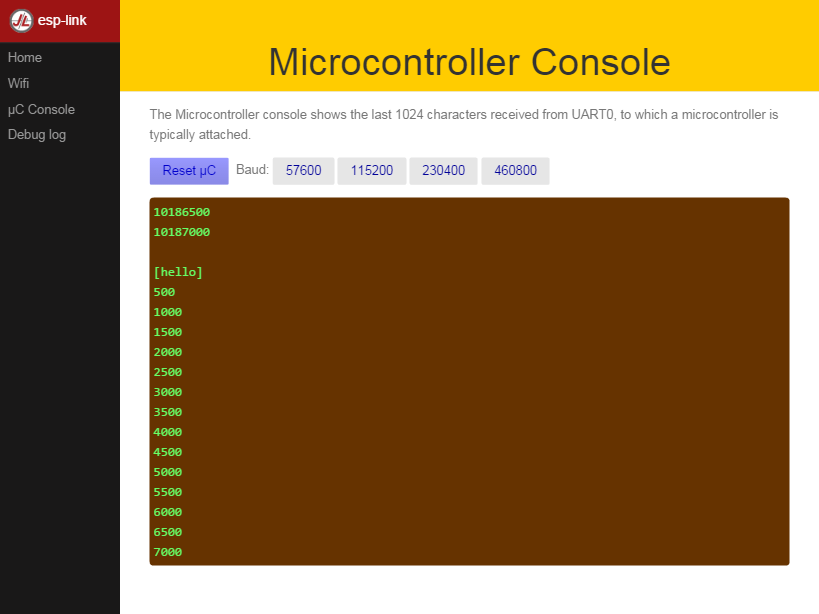
Beware of the baud rate, which you can set on the uC Console page. Sometimes you may be using 115200 baud in sketches but the bootloader may use 57600 baud. When you use port 23 or 2323 you need to set the baud rate correctly. If you use the built-in programmer (HTTP POST method) then esp-link will try the configured baud rate and also 9600, 57600, and 115200 baud, so it should work even if you have the wrong baud rate configured…
When to use which method? If port 23 works then go with that. If you have trouble getting sync or it craps out in the middle too often then try the built-in programmer with the HTTP POST. If your AVR doesn’t use optiboot then use port 2323 since esp-link may not recognize the programming sequence and not issue a reset if you use port 23.
If you are having trouble with the built-in programmer and see something like this:
|
1 2 3 |
# ./avrflash 192.168.3.104 blink.hex Error checking sync: FAILED to SYNC: abandoned after timeout, got: :\xF/\x00\xCj\xCz\xCJ\xCZ\xC\xAÜ\xC\xAä\xC\xAÜ\xC\xAä\xC\xBì\xC\xBô\xC\xBì\xC\xBô\xC\xAÜ\xC\xAä\xC |
the most likely cause is a baud rate mismatch and/or a bad connection from the esp8266 to the AVRs reset line. The baud rate used by esp-link is set on the uC Console web page and, as mentioned above, it will automatically try 9600, 57600, and 115200 as well. The above garbage characters are most likely due to optiboot timing out and starting the sketch and then the sketch sending data at a different baud rate than configured into esp-link. Note that sketches don’t necessarily use the same baud rate as optiboot, so you may have the correct baud rate configured but reset isn’t functioning, or reset may be functioning but the baud rate may be incorrect.
The output of a successful flash using the built-in programmer looks like this:
|
1 |
Success. 3098 bytes at 57600 baud in 0.8s, 3674B/s 63% efficient |
This says that the sketch comprises 3098 bytes of flash, was written in 0.8 seconds (excludes the initial sync time) at 57600 baud, and the 3098 bytes were flashed at a rate of 3674 bytes per second. The efficiency measure is the ratio of the actual rate to the serial baud rate, thus 3674/5760 = 0.63 (there are 10 baud per character). The efficiency is not 100% because there is protocol overhead (such as sync, record type, and length characters) and there is dead time waiting for an ack or preparing the next record to be sent.
Flashing an attached ARM processor
You can reprogram NXP’s LPC800-series and many other ARM processors as well by pointing your programmer similarly at the esp-link’s port 23. For example, if you are using https://github.com/jeelabs/embello/tree/master/tools/uploader a command line like uploader -t -s -w esp-link:23 build/firmware.bin does the trick. The way it works is that the uploader uses telnet protocol escape sequences in order to make esp-link issue the appropriate “ISP” and reset sequence to the microcontroller to start the flash programming. If you use a different ARM programming tool it will work as well as long as it starts the connection with the ?\r\n synchronization sequence.
Flashing an attached esp8266
Yes, you can use esp-link running on one esp8266 module to flash another esp8266 module, however it is rather tricky! The problem is not electric, it is wifi interference. The basic idea is to use some method to direct the esp8266 flash program to port 2323 of esp-link. Using port 2323 with the appropriate wiring will cause the esp8266’s reset and gpio0 pins to be toggled such that the chip enters the flash programming mode.
One option for connecting the programmer with esp-link is to use my version of esptool.py at http://github.com/tve/esptool, which supports specifying a URL instead of a port. Thus instead of specifying something like --port /dev/ttyUSB0 or --port COM1 you specify --port socket://esp-link.local:2323. Important: the baud rate specified on the esptool.py command-line is irrelevant as the baud rate used by esp-link will be the one set in the uC console page. Fortunately the esp8266 bootloader does auto-baud detection. (Setting the baud rate to 115200 is recommended.)
Another option is to use a serial-to-tcp port forwarding driver and point that to port 2323 of esp-link. On windows users have reported success with HW Virtual Serial Port
Now to the interference problem: once the attached esp8266 is reset it starts outputting its 26Mhz clock on gpio0, which needs to be attached to the esp8266 running esp-link (since it needs to drive gpio0 low during the reset to enter flash mode). This 26Mhz signal on gpio0 causes a significant amount of radio interference with the result that the esp8266 running esp-link has trouble receiving Wifi packets. You can observe this by running a ping to esp-link in another window: as soon as the target esp8266 is reset, the pings become very slow or stop altogetehr. As soon as you remove power to the attached esp8266 the pings resume beautifully.
To try and get the interference under control, try some of the following: add a series 100ohm resistor and 100pf capacitor to ground as close to the gpio0 pin as possible (basically a low pass filter); and/or pass the cable connecting the two esp8266’s through a ferrite bead.
Debug log
The esp-link web UI can display the esp-link debug log (os_printf statements in the code). This is handy but sometimes not sufficient. Esp-link also prints the debug info to the UART where it is sometimes more convenient and sometimes less… For this reason three UART debug log modes are supported that can be set in the web UI (and the mode is saved in flash):
- auto: the UART log starts enabled at boot using uart0 and disables itself when esp-link associates with an AP. It re-enables itself if the association is lost.
- off: the UART log is always off
- on0: the UART log is always on using uart0
- on1: the UART log is always on using uart1 (gpio2 pin)
Note that even if the UART log is always off the ROM prints to uart0 whenever the esp8266 comes out of reset. This cannot be disabled.
Outbound HTTP REST requests and MQTT client
The V2 versions of esp-link support the espduino SLIP protocol that supports simple outbound HTTP REST requests as well as an MQTT client. The SLIP protocol consists of commands with binary arguments sent from the attached microcontroller to the esp8266, which then performs the command and responds back. The responses back use a callback address in the attached microcontroller code, i.e., the command sent by the uC contains a callback address and the response from the esp8266 starts with that callback address. This enables asynchronous communication where esp-link can notify the uC when requests complete or when other actions happen, such as wifi connectivity status changes.
You can find a demo sketch in a fork of the espduino library at https://github.com/tve/espduino in the examples/demo folder.
Screens:
Console output (115200 baud)
|
1 2 3 4 5 6 7 8 9 10 11 12 13 14 15 16 17 18 19 20 21 22 23 24 25 26 27 28 29 30 31 32 33 34 35 36 37 38 39 40 41 42 43 44 45 46 47 48 49 50 51 52 53 |
310> 310> ** esp-link v2.2.3 - 2016-06-21 21:58:48 - 1bcdc62 311> Flash config restore *FAILED* 311> CONN led=0 314> Wifi init, mode=AP 316> Wifi uses DHCP, hostname=esp-link 319> "ip": "0.0.0.0" 321> "netmask": "0.0.0.0" 324> "gateway": "0.0.0.0" 327> "hostname": "<null>" 329> sleep enable,type: 2 332> Httpd init, conn=0x3fff2a6c 335> Serbridge pins: reset=12 isp=13 swap=0 348> Reset cause: 6=external 348> exccause=0 epc1=0x0 epc2=0x0 epc3=0x0 excvaddr=0x0 depc=0x0 348> Flash map 1MB:512/512, manuf 0xE0 chip 0x4014 353> ** esp-link v2.2.3 - 2016-06-21 21:58:48 - 1bcdc62: ready, heap=25112 360> initializing user application 363> Waiting for work to do... 366> mode : softAP(5e:cf:7f:0d:7e:a1) 370> add if1 372> dhcp server start:(ip:192.168.4.1,mask:255.255.255.0,gw:192.168.4.1) 380> bcn 100 6530> chg_A2:-40 13761> add 1 13761> aid 1 mobiele telefoon verbonden: 13761> station: 48:3c:0c:68:c2:32 join, AID = 1 13762> Wifi AP: station 48:3c:0c:68:c2:32 joined, AID = 1 15332> Wifi check: mode=AP status=255 192.168.4.1 (homepage) geladen: 71470> HTTP GET /: 302, 4ms, h=21728 71507> HTTP GET /home.html: 200, 40ms, h=22112 72126> /pure.css not found. 404! 72132> HTTP GET /pure.css: 302, 8ms, h=17992 72141> HTTP GET /style.css: 200, 17ms, h=20072 72143> HTTP GET /ui.js: 200, 18ms, h=21776 72158> /favicon.ico not found. 404! 72160> HTTP GET /favicon.ico: 302, 3ms, h=22120 72345> HTTP GET /menu: 200, 29ms, h=18512 72346> HTTP GET /pins: 200, 24ms, h=18712 72347> HTTP GET /wifi/info: 200, 16ms, h=18904 72350> HTTP GET /system/info: 200, 11ms, h=20960 72357> /favicon.ico not found. 404! 72359> HTTP GET /favicon.ico: 0, 15ms, h=22128 72369> /favicon.ico not found. 404! 72372> HTTP GET /favicon.ico: 200, 4ms, h=22128 |
|
1 2 3 4 5 6 7 8 9 10 11 12 13 14 15 16 17 18 19 20 21 22 23 24 25 26 27 28 29 30 31 32 33 34 35 36 37 38 39 40 41 42 43 44 45 46 47 48 49 50 51 52 53 54 55 56 57 58 59 60 61 62 63 64 65 66 67 68 69 70 71 72 73 74 75 76 77 78 79 80 81 82 83 84 85 |
Changes since v2.1.beta4: added automatic switching to 9600/57600/115200 baud when using built-in AVR programmer (it will try the baud rate set on the uC Console page first) changed pin config to allow control over individual pin assignments added option for internal pull-up on RX pin merged "system name" shown in menu bar and "hostname" used for DHCP (and mDNS someday) changed home page around compiled with SDK v1.4.1_pre7 Changes since v2.1.beta3: disabled mDNS 'cause free complains about memory already freed: I think the SDK's mDNS is buggy... added option to select uart1 for debug log added drop-down for baud rates, warning pgm baud rate selection is non-functional fixed style of uC console page, now 100% height Changes since v2.1.beta2: uC console text input courtesy https://github.com/katyo first cut at mDNS support, not happy yet... first cut at supporting hidden SSIDs improved click-to-edit name/description fields extended AP+STA time before switching to STA-only Changes since v2.1.beta1: new esp-link summary card on home page with, among other things, info on the flash chip and configured size new editable 12-character "name" displayed on home page and in left menu bar so you know which esp-link module you're looking at new editable 128 character "description" displayed on home page so you can leave yourself a memo about this module Changes since v2.0.rc1: single image fits any esp module flash size, no OTA reflashing of esp-link with 512KB modules though built-in optiboot programmer attempt to fix crash when scanning and there are too many access points around (I have not been able to really test the fix yet) Changes since v1.0.3: Increase serbridge buffer to 2*1460 bytes and ensure esp-link doesn't lock-up on printing errors for buffer overflow Changes since v1.0.1: - rewrite of serial bridge buffering to fix problem with high data rates Changes since v1.0.0: - support esp-12/4MB flash size; - support 1MB flash size; - support UART pin swap (see below); - misc minor fixes Changes since v0.10.3: - fix handling of baud rate mismatches; - allow uart log to be disabled Changes since v0.10.2: - fix hamburger menu; - improve serial LED; - improve layout on small devices; - change default patched SDK path not to have 'p' suffix Changes since v0.10.1: - remove html templating entirely; - fix memory leak; - fix caching; - improve layout on small screens; - support static IPs (UI is still rudimentary); - support DHCP hostname Changes since v0.10.0: - fix crash when rapidly hitting F5 in web browser Changes since v0.9.5: - complete rewrite of web pages using ajax; - added pin configuration; - saving pin config in flash Changes since v0.9.4: - switched console to ajax auto-update, - added reset button, - added baud rate buttons Changes since v0.9.3: - added defines in the Makefile to change GPIO pin assignments, - fixed buffer overrun bug in uC console page. Changes since v0.9.2: - added telnet escape sequence support, - switched to pure-css, - many other fixes. Changes since v0.9.1: - web page improvements |