IC – L293D – Dual H-bridge motor driver
Hardware
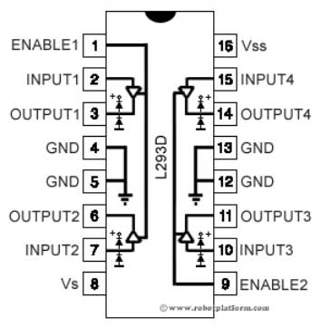
De L293D Motor driver bezit 4 H-bruggen voor het aansturen van DC of stappenmotoren.
Met deze chip kun je twee motoren tegelijk besturen, en kun je tevens de motoren beide richtingen op laten draaien. Ook wel beken als h-bridge (h-brug).
Ideaal voor rijdende robots of de besturing van je robot-arm.
Pinout
Informatie (ENG):
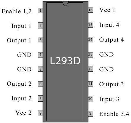
CONNECTIONS IN L293D
- Pin1 and Pin9 are “Enable” pins or the switch pins as you can say. They should be connected to +5V for the drivers to function (for the motor to follow the inputs). If they pulled low (GND), then the outputs will be turned off regardless of the input states, stopping the motors.
- Pin4, Pin5, Pin12 and Pin 13 are ground pins which should ideally be connected to microcontroller’s ground.
- Pin2, Pin7, Pin10 and Pin15 are logic input pins. These are control pins which should be connected to microcontroller pins or whatever is the input to L293D. Pin2 and Pin7 control the left motor ; Pin10 and Pin15 control the right motor. (as shown in diagram)
- Pin3, Pin6, Pin11, and Pin 14 are output pins. Tie Pin3 and Pin6 to the left motor, Pin11 and Pin 14 to right motor. Note that there is a bijection between the input pins and output pins.
- Pin16 powers the IC and it should be connected to regulated +5Volts.
- Pin8 powers the two motors and should be connected to positive lead of a secondary battery. As per the datasheet, supply voltage can be as high as 36 Volts.As we can see the highest output is 36V so considerably larger motor can also be driven using this IC.
Truth Table
The truth table will explain you that how to make connections for the motor if you want it to move in either clockwise or anti clockwise direction.
| PIN 1 (Enable) | PIN2 | PIN7 | OUTPUT |
| High | High | Low | Turn Anti Clockwise |
| High | Low | High | Turn Clockwise |
| High | High | Low | Stop |
| High | Low | High | Stop |
| Low | Doesn’t matter | Doesn’t matter | Doesn’t matter |
MOTOR CONTROL PINS
| EN1 | Enable Motor 1 |
| EN2 | Enable Motor 2 |
| IN1 | Direction 1 Motor A |
| IN2 | Direction 2 Motor A |
| IN3 | Direction 1 Motor B |
| IN4 | Direction 2 Motor B |
PIN VALUES AND MEANING TO THE BRIDGE AND MOTORS
| PIN | Value | |
| IN1 | HIGH | Enables Motor A |
| LOW | Disables Motor A | |
| IN2 | HIGH | Enables Motor B |
| LOW | Disables Motor B | |
| IN1 | HIGH | Motor A Forward |
| IN2 | LOW | |
| IN1 | LOW | Motor A Backwards |
| IN2 | HIGH | |
| IN1 | LOW | Motor A Stops |
| IN2 | LOW | |
| IN1 | HIGH | |
| IN2 | HIGH |
The same happens when using EN3 and EN4
Bron(nen):
elec-club-iitb.github.io
electronicshobbyists.com
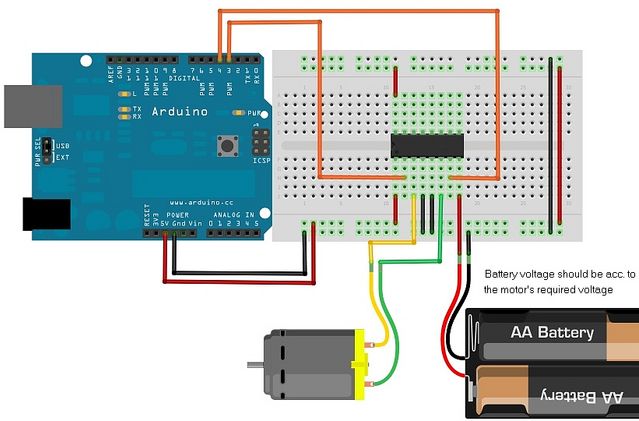
Arduino
Kleine motors zijn te voeden via de Arduino.
Sluit de IC aan volgens onderstaand overzicht:

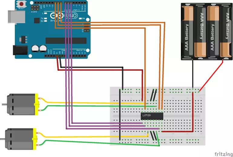
Grotere motors met meer vermogen hebben een aparte voeding nodig.
Sluit de IC aan volgens onderstaand overzicht:
Voorbeeldcode voor bovenstaande schema’s:
|
1 2 3 4 5 6 7 8 9 10 11 12 13 14 |
//Dc motor example code// int motorpin1 = 3; //define digital output pin no. int motorpin2 = 4; //define digital output pin no. void setup () { pinMode(motorpin1,OUTPUT); //set pin 3 as output pinMode(motorpin2,OUTPUT); // set pin 4 as output } void loop () { digitalWrite(motorpin1,LOW); digitalWrite(motorpin2,HIGH); } |
Bron(nen):
communityofrobots.com
Hieronder een voorbeeld schema om 2 motoren aan te sturen:
|
1 2 3 4 5 6 7 8 9 10 11 12 13 14 15 16 17 18 19 20 21 22 23 24 25 26 27 28 29 30 31 32 33 34 35 36 37 38 39 40 41 42 43 44 45 46 47 48 49 50 51 52 53 54 55 56 57 58 59 60 61 62 63 64 65 66 67 68 69 70 |
/** * Bruno Santos, 2013 * feiticeir0@whatgeek.com.pt * Small code to test DC motors - 2x with a L298 Dual H-Bridge Motor Driver * Free to share **/ //Testing the DC Motors with // L293D //Define Pins //Motor A int enableA = 5; int MotorA1 = 6; int MotorA2 = 7; //Motor B int enableB = 8; int MotorB1 = 9; int MotorB2 = 10; void setup() { Serial.begin (9600); //configure pin modes pinMode (enableA, OUTPUT); pinMode (MotorA1, OUTPUT); pinMode (MotorA2, OUTPUT); pinMode (enableB, OUTPUT); pinMode (MotorB1, OUTPUT); pinMode (MotorB2, OUTPUT); } void loop() { //enabling motor A Serial.println ("Enabling Motors"); digitalWrite (enableA, HIGH); digitalWrite (enableB, HIGH); delay (1000); //do something Serial.println ("Motion Forward"); digitalWrite (MotorA1, LOW); digitalWrite (MotorA2, HIGH); digitalWrite (MotorB1, LOW); digitalWrite (MotorB2, HIGH); //3s forward delay (3000); Serial.println ("Motion Backwards"); //reverse digitalWrite (MotorA1,HIGH); digitalWrite (MotorA2,LOW); digitalWrite (MotorB1,HIGH); digitalWrite (MotorB2,LOW); //5s backwards delay (3000); Serial.println ("Stoping motors"); //stop digitalWrite (enableA, LOW); digitalWrite (enableB, LOW); delay (3000); } |
Bron(nen):
blog.whatgeek.com.pt
Raspberry Pi
Sluit de IC aan zoals aangegeven op onderstaand schema:
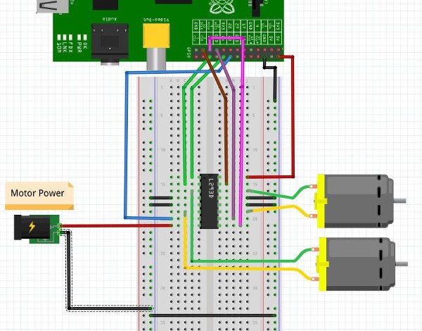
Ps. Altijd de pinout van je Raspberry Pi controleren, deze kan verschillen per versie.
Met onderstaand python script kun je de motoren aansturen
|
1 2 3 4 5 6 7 8 9 10 11 12 13 14 15 16 17 18 19 20 21 22 23 24 25 26 27 28 29 30 31 32 33 34 35 36 37 38 39 40 41 42 43 44 45 46 47 48 49 50 51 52 53 54 55 56 57 58 59 60 61 62 63 64 65 66 67 68 69 70 71 72 73 74 75 76 77 |
#!/usr/bin/python #encoding:utf-8 #Tutorial: http://www.knight-of-pi.org/simple-dc-motor-board-for-the-raspberry-pi-with-ic-l293-and-software-pulse-width-modulation/ #Licence: http://creativecommons.org/licenses/by-nc-sa/3.0/ # Author: Johannes Bergs import RPi.GPIO as GPIO from time import sleep GPIO.setmode(GPIO.BOARD) class Motor: def __init__(self, pinForward, pinBackward, pinControl): """ Initialize the motor with its control pins and start pulse-width modulation """ self.pinForward = pinForward self.pinBackward = pinBackward self.pinControl = pinControl GPIO.setup(self.pinForward, GPIO.OUT) GPIO.setup(self.pinBackward, GPIO.OUT) GPIO.setup(self.pinControl, GPIO.OUT) self.pwm_forward = GPIO.PWM(self.pinForward, 100) self.pwm_backward = GPIO.PWM(self.pinBackward, 100) self.pwm_forward.start(0) self.pwm_backward.start(0) GPIO.output(self.pinControl,GPIO.HIGH) def forward(self, speed): """ pinForward is the forward Pin, so we change its duty cycle according to speed. """ self.pwm_backward.ChangeDutyCycle(0) self.pwm_forward.ChangeDutyCycle(speed) def backward(self, speed): """ pinBackward is the forward Pin, so we change its duty cycle according to speed. """ self.pwm_forward.ChangeDutyCycle(0) self.pwm_backward.ChangeDutyCycle(speed) def stop(self): """ Set the duty cycle of both control pins to zero to stop the motor. """ self.pwm_forward.ChangeDutyCycle(0) self.pwm_backward.ChangeDutyCycle(0) motor1 = Motor(16, 22, 18) motor2 = Motor(23, 19, 21) # Motor 1 test motor1.forward(90) sleep(5) motor1.backward(50) sleep(5) motor1.stop() # Motor 2 test motor2.forward(90) sleep(5) motor2.backward(30) sleep(5) motor2.stop() # Running both motor1.forward(20) motor2.backward(70) sleep(5) motor1.forward(90) sleep(5) motor1.stop() motor2.stop() GPIO.cleanup() |
Start het script met: sudo python motor.py , druk op CTRL+C om het script te stoppen!
Bron:
knight-of-pi.org
Afmetingen
GEEN GEGEVENS
Schema
GEEN GEGEVENS
Teardown
GEEN GEGEVENS
Datasheet
Fritzing
GEEN GEGEVENS
Downloads
GEEN GEGEVENS