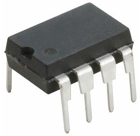
IC – LM386 – Low Voltage Audio Power Amplifier
Hardware
Source: https://components101.com/ics/lm386-audio-amplifier-ic-pinout-circuit-datasheet
The LM386N-1/NOPB is a Wide Vin Class-D low Power Audio Amplifier with internal gain designed for use in low voltage consumer applications. The gain is internally set to 20 to keep external part count low, but the addition of an external resistor and capacitor between pins 1 and 8 will increase the gain to any value from 20 to 200. The inputs are ground referenced while the output automatically biases to one-half the supply voltage. The quiescent power drain is only 24mW when operating from a 6V supply, making the LM386 ideal for battery operation.
LM386 Audio amplifier features and specifications
- Supply Voltage: 4-15V
- Quiescent Power: 24mW @ 6V
- Analog input voltage 0.4V (maximum)
- Voltage Gain: 20 to 200 (26dB to 46dB)
- PSRR: 50dB
- Speaker impedance 4Ω
- Available in 8-Pin PDIP,SOIC and VSSOP packages
LM386 Equivalent IC: LM380
Alternatives Audio Amplifiers: LM4871, AD620, IC6283, JRC4558,
Where to use the LM386 Audio Amplifier
The LM386 is a low power audio frequency amplifier which is very commonly used in small audio amplifiers. The IC consumes very less power and hence can be operated using a 9V battery easily. It can easily drive an 8-ohm speaker with a variable gain of 20 to200. Volume control and gain control is also possible in this. The IC comes in a 8-pin PDIP package and requires very less components to function hence it is highly easy to use.
So, if you are looking for an audio amplifier IC which can be powered using a battery for a portable application to drive an 8-ohm speaker then this IC might be the right choice for you. For driving heavy speakers you have to use the power amplifier ICs.
Applications
- AM and FM Radio amplifiers
- Portable music players
- Low Power Audio amplifiers
- Wienbridge oscillator
- Power Amplifiers
- Audio boosters
Pinout
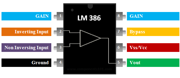
LM386 Pin Configuration
| Pin Number | Pin Name | Description |
| 1,8 | GAIN | Used to set the gain of the IC by connecting to a Capacitor |
| 2 | Inverting Input (IN-) | The Inverting Pin of amplifier is normally grounded |
| 3 | Non-Inverting Input (IN+) | The Non-Inverting pin is provided with the audio signal |
| 4 | Ground | The ground pin is connected to the ground of the system |
| 5 | Vout | Provides amplified audio output, connected to speaker |
| 6 | Vss/Vcc | Connected to power |
| 7 | Bypass | Bypass pin is used for connecting a decoupling capacitor |
Schema
How to use LM386 IC
An application circuit for stereo from TDA2822 datasheet is given below
The LM386 only requires a couple of capacitors and resistors to start working. A very basic commonly used LM386 circuit is shown below.
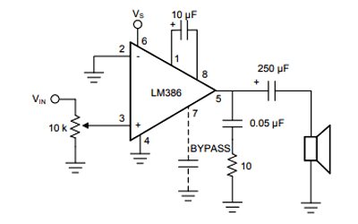
The IC is powered using the pin 6 (typically 5 or 9V) and the ground pin 4 is connected to the ground. The inverting pin (pin 2) is normally grounded and the Non-inverting pin (pin 3) is provided with the Audio signal. This audio signal can be from a microphone or even from a 3.5mm jack. The 10k resistor is added in series with the audio signal to act as a volume control. You can ignore this potentiometer if you want to operate in full volume.
The pin 1 and pin 8 are used to set the gain of the Amplifier. If there is nothing connected between these pins then the default gain will be 26 dB, but we can connect a 10 uF capacitor across it to get the maximum ain of the IC which is 46dB. The pin 7 is used to connect a filtering capacitor (0.1uf) for our amplifier IC to avoid unnecessary oscillations. The amplified audio signal can be obtained from the pin 5 which is connected to a 8-ohm speaker through a filtering capacitor. The RC network with 0.05uF and 10k resistor is optional.
Another schematic with less components:
