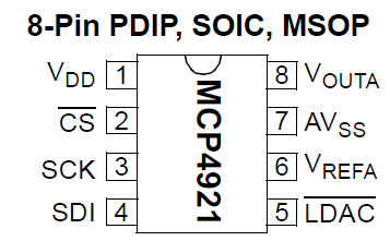
IC – MCP4921 – D/A Converter 12-bit 1 channel SPI
Hardware
Chip:

• ±0.2 LSB DNL (typ)
• ±2 LSB INL (typ)
• Single or Dual Channel
• Rail-to-Rail Output
• SPI™ Interface with 20 MHz Clock Support
• Simultaneous Latching of the Dual DACs w/LDAC
• Fast Settling Time of 4.5 µs
• Selectable Unity or 2x Gain Output
• 450 kHz Multiplier Mode
• External VREF Input
• 2.7V to 5.5V Single-Supply Operation
• Extended Temperature Range: -40°C to +125°C
Pinout
Arduino
Sluit de chip aan volgens onderstaand overzicht:
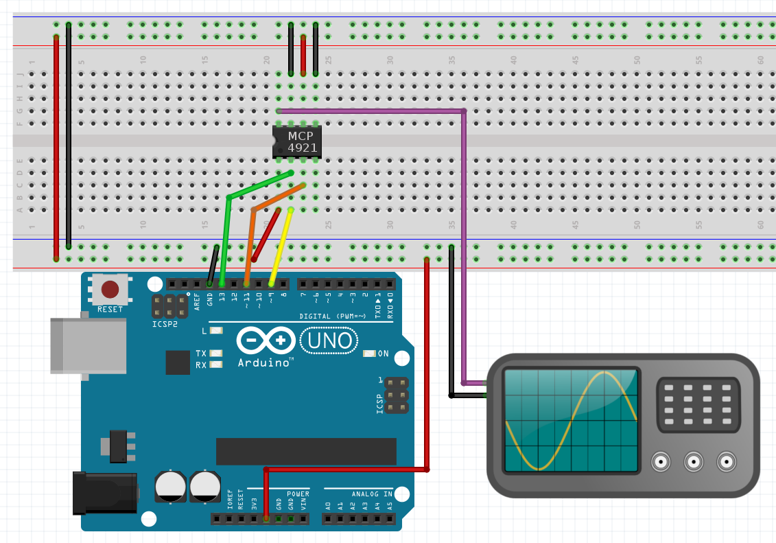

Met onderstaand arduino script kun je de uitgangsvoltage instellen:
|
1 2 3 4 5 6 7 8 9 10 11 12 13 14 15 16 17 18 19 20 21 22 23 24 25 26 27 28 29 30 31 32 33 34 35 36 37 38 39 40 41 42 43 44 45 46 47 48 49 |
//-------------------------------------------- // 12 bit ADC to DAC Example for MCP3202 and MCP4921 // Bart Venneker 2015 //-------------------------------------------- // connections for the ADC mcp3202 // arduino pin 10 = SS (Slave select, pin 1 the chip) // arduino pin 11= Data In (pin 5 on device) // arduino pin 12= Data out (pin 6 on device) // arduino pin 13= clock (pin 7 on device) // // Connections for the DAC mcp4921 // arduino pin 9 = SS (Slave select, pin 2 on the chip) // arduino pin 11= Data In (pin 4 on device) // arduino pin 13= clock (pin 3 on device) // output of the DAC goes to the scope (pin 8 on the chip) // // Supply a signal to channel 0 of the ADC (pin 2 on the chip) // and it will be reproduced by the DAC. // See http://youtu.be/5vOGjIEh7Uk for more info (in DUTCH!) #include <SPI.h> #define CS_DAC 9 void setup() { pinMode(CS_ADC,OUTPUT); digitalWrite(CS_ADC,HIGH); pinMode(CS_DAC,OUTPUT); digitalWrite(CS_DAC,HIGH); SPI.begin(); SPI.setClockDivider(SPI_CLOCK_DIV2); } void loop() { int analogValue = 2048 Write4921(analogValue, CS_DAC) ; } void Write4921(int value, int CS) { byte data; digitalWrite(CS, LOW); data = highByte(value); data = B00001111 & data; data = B00110000 | data; SPI.transfer (data); data = lowByte(value); SPI.transfer (data); digitalWrite(CS, HIGH); } |
Bron: http://www.bartvenneker.nl/Arduino/index.php?art=0015
Script met bibliotheek MCP492X
|
1 2 3 4 5 6 7 8 9 10 11 12 13 14 15 16 17 18 19 20 |
#include <MCP492X.h> // Include the library #define PIN_SPI_CHIP_SELECT_DAC 9 // Or any pin you'd like to use MCP492X myDac(PIN_SPI_CHIP_SELECT_DAC); void setup() { // put your setup code here, to run once: myDac.begin(); } void loop() { // put your main code here, to run repeatedly: // Write any value from 0-4095 myDac.analogWrite(2048); // If using an MCP4922, write a value to DAC B myDac.analogWrite(1, 3172); } |
Arduino Library
This library is built around the Arduino default SPI library and uses the designated SPI pins, in addition to a configurable chip select pin, passed in the constructor.
Installing the library
Method 1: ZIP file
- Download this repository as a .ZIP file: Download Arduino-MCP492X
- Open Arduino IDE
- Click Sketch > Include Library > Add .ZIP library…
- Select the library
- Click Sketch > Include Library > Contributed Libraries > MCP492X
Note: This will install the library on your computer but will not include it within your project if you were to transfer the files to someone else. If you want it all-in-one, I recommend method 2.
Method 2: Include in your project folder
You can also save the .h and .cpp files directly in you arduino project’s folder, and then reference it as follows:
|
1 |
#<span class="pl-k">include</span> <span class="pl-s"><span class="pl-pds">"</span>MCP492X.h<span class="pl-pds">"</span></span> |
You may want to consider making a directory for just libraries though, if you project consists of several files. If the directory inside your project directory called “libs”, the include line changes to:
|
1 |
#<span class="pl-k">include</span> <span class="pl-s"><span class="pl-pds">"</span>libs/MCP492X.h<span class="pl-pds">"</span></span> |
Code
This is the bare minimum to get started with one of these DACs in an Arduino project:
|
1 2 3 4 5 6 7 8 9 10 11 12 13 14 15 16 17 18 19 20 |
#<span class="pl-k">include</span> <span class="pl-s"><span class="pl-pds"><</span>MCP492X.h<span class="pl-pds">></span></span> <span class="pl-c">// Include the library</span> #<span class="pl-k">define</span> <span class="pl-en">PIN_SPI_CHIP_SELECT_DAC</span> <span class="pl-c1">9</span> <span class="pl-c">// Or any pin you'd like to use</span> MCP492X <span class="pl-en">myDac</span>(PIN_SPI_CHIP_SELECT_DAC); <span class="pl-k">void</span> <span class="pl-en">setup</span>() { <span class="pl-c">// put your setup code here, to run once:</span> myDac.<span class="pl-c1">begin</span>(); } <span class="pl-k">void</span> <span class="pl-en">loop</span>() { <span class="pl-c">// put your main code here, to run repeatedly:</span> <span class="pl-c">// Write any value from 0-4095</span> myDac.<span class="pl-c1">analogWrite</span>(<span class="pl-c1">2048</span>); <span class="pl-c">// If using an MCP4922, write a value to DAC B</span> myDac.<span class="pl-c1">analogWrite</span>(<span class="pl-c1">1</span>, <span class="pl-c1">3172</span>); } |
Function descriptions
begin()
Initializes the library, by starting the SPI bus and configuring some settings.
It’s required to call this in setup().
analogWrite(unsigned int value)
Writes a 12-bit value to the DAC output. If this is on an MCP4922, it uses channel A.
analogWrite(bool odd, unsigned int value)
Writes a 12-bit value to a specific DAC output. If this is on an MCP4921, the value passed for odd is ignored. Otherwise, 0 selects the “even” DAC (A), and 1 selects the “odd” DAC (B).
value remains the 12-bit value you want to write.
analogWrite(bool odd, bool buffered, bool gain, bool active, unsigned int value)
Provides full access to all the control bits you can send to the DAC. Consult the data sheet for more information on each of the control bits.
Download @: https://github.com/michd/Arduino-MCP492X
Raspberry Pi
Sluit de IC aan zoals aangegeven op onderstaand schema:

Ps. Altijd de pinout van je Raspberry Pi controleren, deze kan verschillen per versie.
Instellen dmv console commando
Wat heb je nodig?
- SPI aanzetten op de pi via raspi-config
De analoge waarde kan je via de console instellen dmv een 2-byte echo naar de SPI bus
|
1 2 3 4 5 6 7 8 |
# set analog voltage to minimum value (about 0V) echo -ne "\x30\x00" > /dev/spidev0.0 # minimum # set analog voltage to something a little higher echo -ne "\x30\xAB" > /dev/spidev0.0 # set analog voltage to maximum value (about 3.3V) echo -ne "\x3F\xFF" > /dev/spidev0.0 |
Bron: https://swharden.com/blog/2016-09-28-generating-analog-voltages-with-the-raspberry-pi/
Python script ZONDER SPI interface aan op Raspberry pi
Voor onderstaand python script hoeft de SPI interface niet aan te staan, het is een soort van software bit-banging.
|
1 2 3 4 5 6 7 8 9 10 11 12 13 14 15 16 17 18 19 20 21 22 23 24 25 26 27 28 29 30 31 32 33 34 35 36 37 38 |
import time import RPi.GPIO as GPIO GPIO.setmode(GPIO.BCM) GPIO.setwarnings(False) SCLK = 11 # Serial-Clock MOSI = 10 # Master-Out-Slave-In CS = 8 # Chip-Select GPIO.setup(SCLK, GPIO.OUT) GPIO.setup(MOSI, GPIO.OUT) GPIO.setup(CS, GPIO.OUT) def sendSPI(value): GPIO.output(CS, GPIO.HIGH) GPIO.output(SCLK, GPIO.LOW) GPIO.output(CS, GPIO.LOW) for i in range(16): if (value & 0x8000): GPIO.output(MOSI, GPIO.HIGH) else: GPIO.output(MOSI, GPIO.LOW) GPIO.output(SCLK, GPIO.HIGH) GPIO.output(SCLK, GPIO.LOW) value <<= 1 GPIO.output(CS, GPIO.HIGH) sendSPI(0x30FF) time.sleep(3) sendSPI(0x38FF) time.sleep(3) sendSPI(0x3FFF) time.sleep(3) |
Bron: https://forum-raspberrypi.de/forum/thread/15880-mcp4921-ansprechen/
Python script icm bibliotheek
Wat heb je nodig?
- SPI aanzetten op de pi via raspi-config
|
1 2 3 4 5 6 7 8 9 10 11 12 13 14 15 16 17 18 19 20 21 22 23 24 25 26 27 28 29 30 31 32 33 34 35 36 37 38 39 |
#!/usr/bin/python # Python Library for MCP4922 DAC # 2 Channels, 12 Bit import time import sys import RPi.GPIO as GPIO from MCP4922 import MCP4922 GPIO.setmode(GPIO.BCM) # use the Broadcom pin numbering GPIO.setwarnings(False) # disable warnings if __name__ == '__main__': dac = MCP4922() try: while True: x = 0 for i in range(0, 100): x = x + 40 dac.setVoltage(0, x) dac.setVoltage(1, x) print(x) time.sleep(0.1) for i in range(0, 100): x = x - 40 dac.setVoltage(0, x) dac.setVoltage(1, x) print(x) time.sleep(0.1) except KeyboardInterrupt: # Press CTRL C to exit program dac.setVoltage(0, 0) dac.setVoltage(1, 0) dac.shutdown(0) dac.shutdown(1) GPIO.cleanup() sys.exit(0) |
Raspberry Pi Library
Python Library for driving MCP4922 DAC (Digital to Analog Converter) on Raspberry Pi
Installation
To install the library run the following commands on a Raspberry Pi or other Debian-based OS system:
Install Git
If you don’t have it already:
|
1 |
sudo apt-get install git build-essential python-dev |
Requirements
To run this module you need RPi.GPIO and spidev:
|
1 2 |
sudo pip install RPi.GPIO sudo pip install spidev |
Clone the repository
|
1 |
git clone https://github.com/mrwunderbar666/Python-RPi-MCP4922.git |
|
1 2 3 4 5 6 |
loning into 'Python-RPi-MCP4922'... remote: Enumerating objects: 56, done. remote: Counting objects: 100% (56/56), done. remote: Compressing objects: 100% (34/34), done. remote: Total 56 (delta 20), reused 56 (delta 20), pack-reused 0 Unpacking objects: 100% (56/56), done. |
Install with Setup.py
|
1 2 |
<span class="pl-c1">cd</span> Python-RPi-MCP4922 sudo python setup.py install |
|
1 2 3 4 5 6 7 8 9 10 11 12 13 14 15 16 17 18 19 20 21 22 23 24 25 26 27 28 29 30 31 32 33 34 35 36 37 38 39 40 41 42 43 44 45 46 47 48 49 50 51 52 53 |
running install running bdist_egg running egg_info creating Python_RPi_MCP4922.egg-info writing requirements to Python_RPi_MCP4922.egg-info/requires.txt writing Python_RPi_MCP4922.egg-info/PKG-INFO writing top-level names to Python_RPi_MCP4922.egg-info/top_level.txt writing dependency_links to Python_RPi_MCP4922.egg-info/dependency_links.txt writing manifest file 'Python_RPi_MCP4922.egg-info/SOURCES.txt' reading manifest file 'Python_RPi_MCP4922.egg-info/SOURCES.txt' writing manifest file 'Python_RPi_MCP4922.egg-info/SOURCES.txt' installing library code to build/bdist.linux-armv7l/egg running install_lib running build_py creating build creating build/lib.linux-armv7l-2.7 creating build/lib.linux-armv7l-2.7/MCP4922 copying MCP4922/__init__.py -> build/lib.linux-armv7l-2.7/MCP4922 copying MCP4922/MCP4922.py -> build/lib.linux-armv7l-2.7/MCP4922 creating build/bdist.linux-armv7l creating build/bdist.linux-armv7l/egg creating build/bdist.linux-armv7l/egg/MCP4922 copying build/lib.linux-armv7l-2.7/MCP4922/__init__.py -> build/bdist.linux-armv7l/egg/MCP4922 copying build/lib.linux-armv7l-2.7/MCP4922/MCP4922.py -> build/bdist.linux-armv7l/egg/MCP4922 byte-compiling build/bdist.linux-armv7l/egg/MCP4922/__init__.py to __init__.pyc byte-compiling build/bdist.linux-armv7l/egg/MCP4922/MCP4922.py to MCP4922.pyc creating build/bdist.linux-armv7l/egg/EGG-INFO copying Python_RPi_MCP4922.egg-info/PKG-INFO -> build/bdist.linux-armv7l/egg/EGG-INFO copying Python_RPi_MCP4922.egg-info/SOURCES.txt -> build/bdist.linux-armv7l/egg/EGG-INFO copying Python_RPi_MCP4922.egg-info/dependency_links.txt -> build/bdist.linux-armv7l/egg/EGG-INFO copying Python_RPi_MCP4922.egg-info/requires.txt -> build/bdist.linux-armv7l/egg/EGG-INFO copying Python_RPi_MCP4922.egg-info/top_level.txt -> build/bdist.linux-armv7l/egg/EGG-INFO zip_safe flag not set; analyzing archive contents... creating dist creating 'dist/Python_RPi_MCP4922-0.3-py2.7.egg' and adding 'build/bdist.linux-armv7l/egg' to it removing 'build/bdist.linux-armv7l/egg' (and everything under it) Processing Python_RPi_MCP4922-0.3-py2.7.egg Copying Python_RPi_MCP4922-0.3-py2.7.egg to /usr/local/lib/python2.7/dist-packages Adding Python-RPi-MCP4922 0.3 to easy-install.pth file Installed /usr/local/lib/python2.7/dist-packages/Python_RPi_MCP4922-0.3-py2.7.egg Processing dependencies for Python-RPi-MCP4922==0.3 Searching for spidev==3.4 Best match: spidev 3.4 Adding spidev 3.4 to easy-install.pth file Using /usr/lib/python2.7/dist-packages Searching for RPi.GPIO==0.7.0 Best match: RPi.GPIO 0.7.0 Adding RPi.GPIO 0.7.0 to easy-install.pth file Using /usr/lib/python2.7/dist-packages Finished processing dependencies for Python-RPi-MCP4922==0.3 |
Software
Getting started
Go to the example directory and execute the test script:
|
1 2 |
<span class="pl-c1">cd</span> examples sudo python MCP4922_test.py |
This script will initialize the MCP4922 and incrementally increase the voltage on both channels. Then it will decrease the voltage and loop forever.
If you want to manually set the channel and voltage, you can use the other test script:
|
1 |
sudo python MCP4922_set.py |
Use it in your own code
Setup
First import the required GPIO module in python:
|
1 |
<span class="pl-k">import</span> <span class="pl-v">RPi</span>.<span class="pl-v">GPIO</span> <span class="pl-k">as</span> <span class="pl-v">GPIO</span> |
Set your pin mode to BCM:
|
1 |
<span class="pl-v">GPIO</span>.<span class="pl-en">setmode</span>(<span class="pl-v">GPIO</span>.<span class="pl-v">BCM</span>) |
and then import the MCP4922 module:
|
1 |
<span class="pl-k">from</span> <span class="pl-v">MCP4922</span> <span class="pl-k">import</span> <span class="pl-v">MCP4922</span> |
MCP4922 Class
The MCP4922 Class takes 3 arguments: spibus, spidevice and cs. To configure just simple use this code in python:
|
1 |
<span class="pl-s1">dac</span> <span class="pl-c1">=</span> <span class="pl-v">MCP4922</span>(<span class="pl-s1">spibus</span><span class="pl-c1">=</span><span class="pl-c1">0</span>, <span class="pl-s1">spidevice</span><span class="pl-c1">=</span><span class="pl-c1">0</span>, <span class="pl-s1">cs</span><span class="pl-c1">=</span><span class="pl-c1">8</span>) |
spibus
Select the bus for your MCP4922. Should be either 0 or 1. If no argument is given it will turn to the default of 0.
Have a closer look at the spidev module (https://github.com/doceme/py-spidev) for more details.
spidevice
Select the device connected to the bus, should be either 0 or 1. If no argument is given it will turn to the default of 1.
Also checkout the spidev documentation for more details.
cs
Chip select pin. Enter the pin number (Broadcom or Physical pin) where the MCP4922 is connected to. If no argument is given it will turn to the default of 8 (Broadcom pin numbering) or 24 (physical pin numbering).
setVoltage(channel, value)
This method sets the desired output voltage at the requested channel. It is as easy as:
|
1 |
<span class="pl-s1">dac</span>.<span class="pl-en">setVoltage</span>(<span class="pl-c1">0</span>, <span class="pl-c1">2048</span>) |
This will set the voltage output to 50% of the reference voltage.
channel
The MCP4922 has two channels, you can select by giving the arguments 0 or 1. 0 is channel A, 1 is channel B.
Anything else will throw an error at you.
value
Interger value from 0 to 4095, where 4095 is 100% of the reference voltage.
If you insert a value beyond that reach it will be clamped to 4095 (or 0 if you give a negative value).
setVoltage_gain(channel, value)
The MCP4922 has the ability to output the double of the reference Voltage Reference Voltage is measured by the MCP4922 at pin 13 (VrefA) for Channel A and pin 11 (VrefB) for Channel B Note that the output voltage cannot exceed the supply voltage from pin 1 (VDD).
Example:
|
1 |
<span class="pl-s1">dac</span>.<span class="pl-en">setVoltage_gain</span>(<span class="pl-c1">0</span>, <span class="pl-c1">2048</span>) |
setVoltage_buffered(channel, value)
Using the buffer feature of the MCP4922, refer to the datasheet for details.
Example:
|
1 |
<span class="pl-s1">dac</span>.<span class="pl-en">setVoltage_buffered</span>(<span class="pl-c1">0</span>, <span class="pl-c1">2048</span>) |
shutdown(channel)
Completely shutdown selected channel for power saving. Sets the output of selected channel to 0 and 500K Ohms. Read Datasheet (SHDN) for details.
Example:
|
1 |
<span class="pl-s1">dac</span>.<span class="pl-en">shutdown</span>(<span class="pl-c1">1</span>) |
Download @: https://github.com/mrwunderbar666/Python-RPi-MCP4922
Afmetingen
GEEN GEGEVENS
Schema
GEEN GEGEVENS
Teardown
GEEN GEGEVENS
Datasheet
Fritzing
GEEN GEGEVENS
Downloads
GEEN GEGEVENS