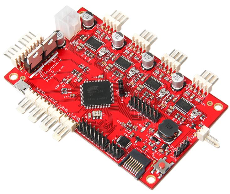
Mechanica Hardware – Printrboard
![]()
Informatie (ENG):
Hardware
The Printrboard electronic set was designed by members of the Printrbot team in order to eliminate the production and functionality shortcomings of older RepRap electronics sets. Printrboard improves upon the previous production-grade electronics set (Gen6) by adding heatbed and SD card support, reverting to 1/16 microstepping Allegro stepper drivers, and improving connectivity reliability and reducing cost by elimination of the FTDI UART chip. Printrboard also has expansion headers supporting I2C, SPI, UART, and ADC pins. All extra I/O ports of the AT90USB have been broken out to headers for prototyping and expansion.
Printrboard is a derivative of Teensylu, an AT90USB1286 development board originally based on Sanguinololu. The Atmel AT90USB1286 MCU has on-chip USB, removing the need for the FTDI UART (USB-to-serial) IC. On-chip USB means dramatically faster firmware upload times and communication. The AT90USB connects at any baud rate regardless of firmware configuration, and operates virtually free of serial communication errors/pauses.
Features
-
- Atmel AT90USB1286 Microcontroller (or AT90USB1287 drop-in compatible for 20mhz support)
- — Native USB interface. No FTDI serial-to-USB chip!
- — 128kb Flash
-
- Four integrated Allegro A4982 Stepper Drivers (no Pololus needed)
- On-board 4-channel DAC to control stepper set current (Rev F)
- Thermistor Connectivity: 2
- 2 N-MOSFETs for Extruder and Heatbed control
- 1 N-MOSFET for low power Fan or motor
- Onboard SD card slot
- Four Endstop connectors supplied @ 5V. Includes X, Y, Z, and fourth endstop called E-Stop to be used as an emergency stop, or extruder stop (to be added in firmware).
- Supports multiple power configurations (Carried from Sanguinololu)
- — Logic & Motors supplied by ATX or laptop power supply (12-20V 120W minimum)
- — Logic supplied by USB bus (if enabled by solder jumper)
- — Logic supplied by on-board voltage regulator
- — on-board USB connectivity
-
- Edge connectors enabling right-angle connections
- Dedicated I2C connector (Rev F)
- 14 Extra pins available for expansion and development, with the following capabilities
- — UART1 (RX and TX)
- — SPI (MOSI, MISO, SCK)
- — PWM pin (1)
- — Analog I/O (6)
- — JTAG (uses some of the ADC pins)
-
- Additional 14 pin header with remaining I/O for prototyping
- SMT Components sized at 0805, and no QFNs for easier soldering.
- 4-Layer PCB with proper ground plane and power distribution networks
- Small design – board is 100mm x 60mm (4″ x 2.4″)
Software
All preassembled Printrboards come pre-loaded with a bootloader and firmware. You may wish to use alternative (or newer) firmware, modify calibration data for use with another style of RepRap, or perhaps assemble your own board.
To use a Printrboard, you will need to load appropriate USB drivers, either get it from
- Windows-only: USB Serial Device (PRJC.com) or
- Windows/Mac/Linux: packaged with Atmel’s FLIP software.
Compatible Firmware
- Sprinter: Supported, use MOTHERBOARD == 9.
- Marlin: Supported, use MOTHERBOARD == 81 or 811. Also works with Lincomatic’s fork.
- Repetier: Supported, use MOTHERBOARD == 9.
- Grbl: No official support yet, but works with Lincomatic’s fork.
(Other firmwares are currently untested but any firmware for an ATmega should work with proper pin setup.)
Bootloaders
There is no native Arduino bootloader for the AT90USB series microcontrollers, however, there is excellent opensource support for the MCU and Arduino integration is easily achieved.
- LUFA’s CDC Bootloader: Allows direct uploading of firmware through Arduino/avrude via avr109 protocol. Requires no driver on Linux/Mac and free INF installer to use the built-in Windows driver, and Arduino 022 with modified Teensylu boards configuration. Avrdude within Arduino directory must also be upgraded to newest version. Limited to 64k flash space by the protocol. Note that this is a severe limitation rendering most modern firmwares (with e.g. SD card and/or graphical display support) unusable.
- LUFA’s HID Bootloader: No Arduino integration. An Arduino support package is tentatively offered here, making this the best (no driver required, full 128k) bootloader option, with the sole drawback that this particular bootloader is the least prevalent, meaning you almost always have to flash the bootloader yourself. No drivers required. Allows firmware to be uploaded by command prompt.
- Atmel’s DFU Bootloader: Factory installed bootloader. No Arduino integration. Allows firmware to be uploaded by Atmel’s free FLIP software (Windows only). See Teensylu#Sprinter for Mac/Linux equivalent “dfu-programmer”.
Installing A Bootloader
If you wish to change to a different bootloader, you will need a USBtinyISP or equivalent ICSP or JTAG programmer. Note that USBTiny only officially supports MCU’s with less <= 64K flash (the AT90USB1286 is a 128K chip!). Writing will work with a USBTiny, but read verification will always fail.
- Obtain a compiled bootloader (CDC, HID, or DFU). See Lincomatic’s Bootloaders for AT90USB1286 article for pre-compiled copies of each bootloader.
- Remove the BOOT jumper from the Printrboard. Press the Reset button
- Connect the 6 pin programming cable to the Printrboard’s ICSP header. Pin 1 (red wire) is closest to the SD card slot.
- Connect your programmer’s USB cable.
- Run the following avrdude commands, where BootloaderNAME_HERE.hex is the name of the Bootloader file you wish to install
|
1 2 |
avrdude -c usbtiny -p at90usb1286 -U lfuse:w:0xDE:m -U hfuse:w:0x9B:m -U efuse:w:0xF0:m avrdude -c usbtiny -p at90usb1286 -U flash:w:BootloaderNAME_HERE.hex:i |
- Replace jumper on the Printrboard. Press Reset again.
WARNING: Triple check the fuse values! Setting incorrect values will brick the microcontroller! Fuse values above are for the CDC and HID bootloaders. Fuses for the factory DFU bootloader should be set as
|
1 |
avrdude -c usbtiny -p at90usb1286 -U lfuse:w:0x5E:m -U hfuse:w:0x99:m -U efuse:w:0xF3:m |
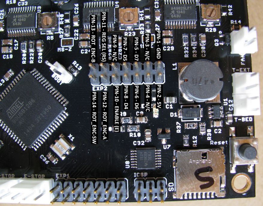
Pinout:
LET OP: In bovenstaande moet EXP1 omgedraaid worden met EXP2 !!
Pinout header EXP1 + ISP (onder)
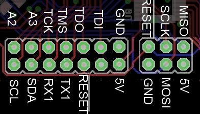
Pinout header EXP2 (midden)
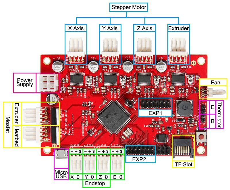
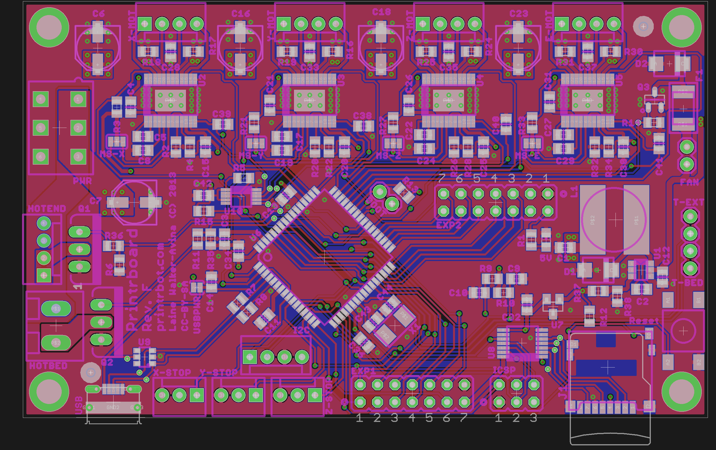
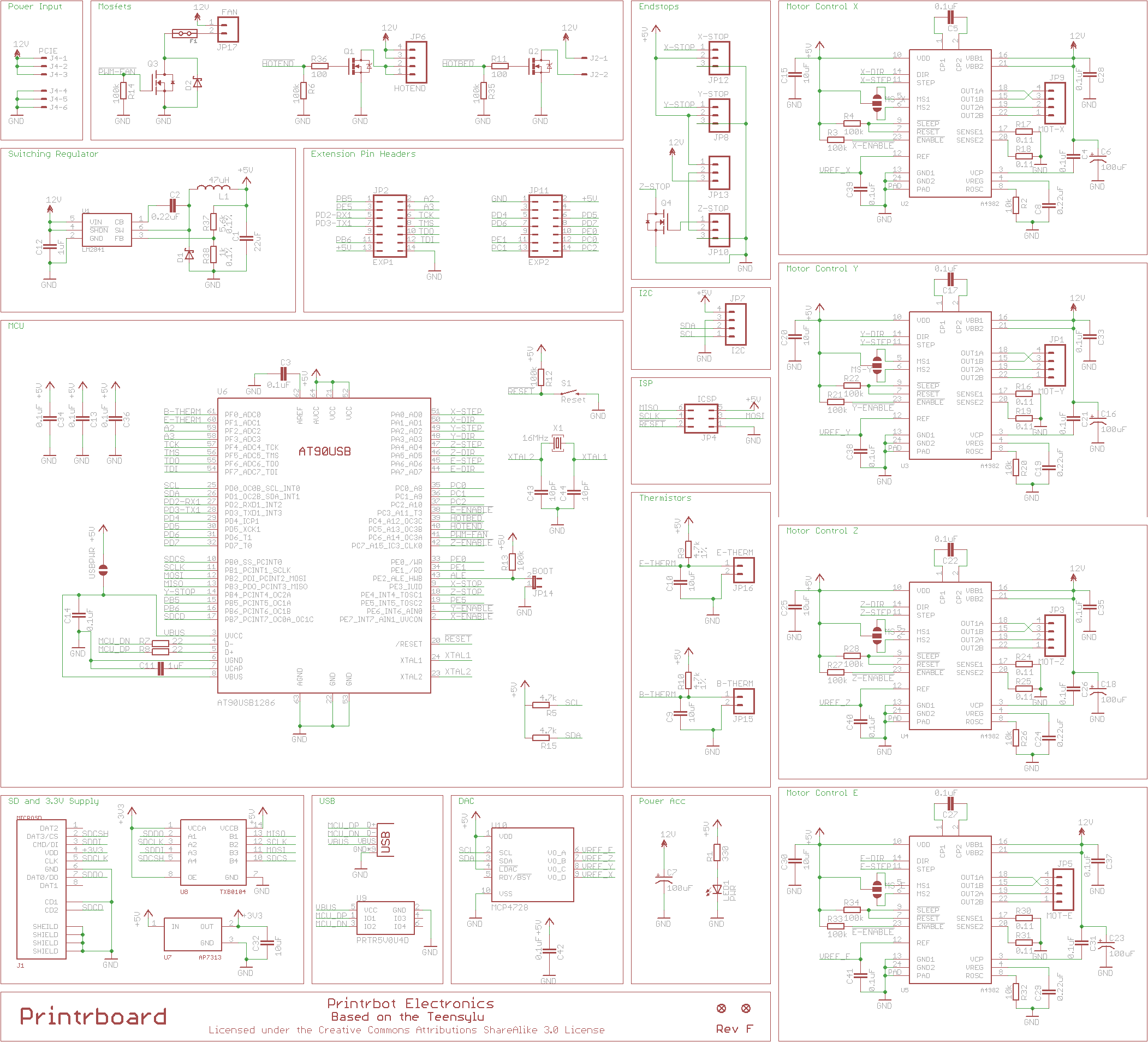
Interface layout:
PrintrBoard REV D
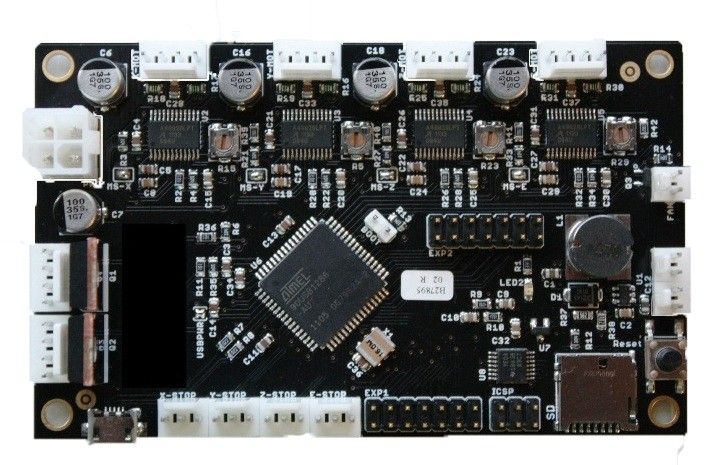
Pinout:


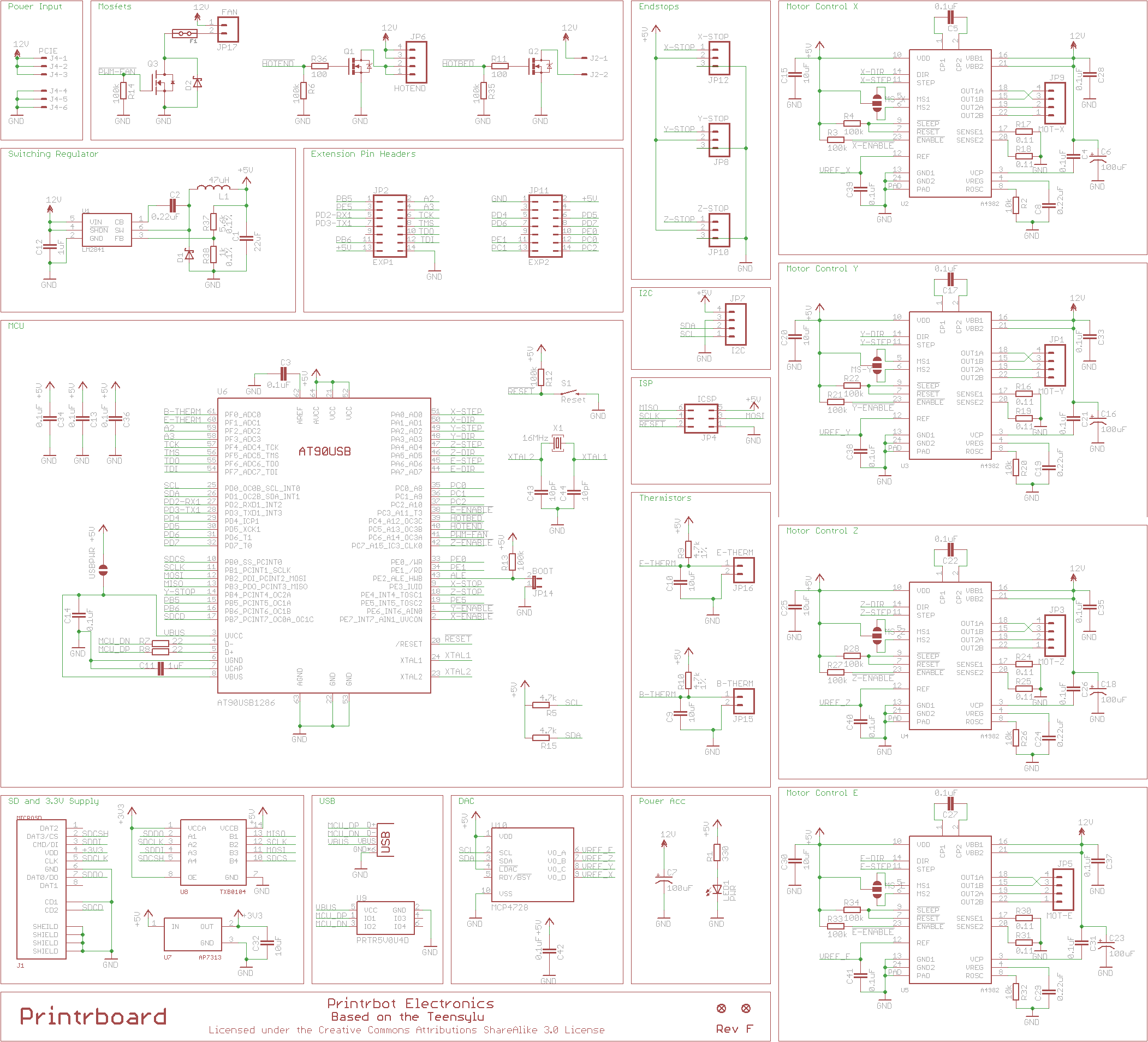
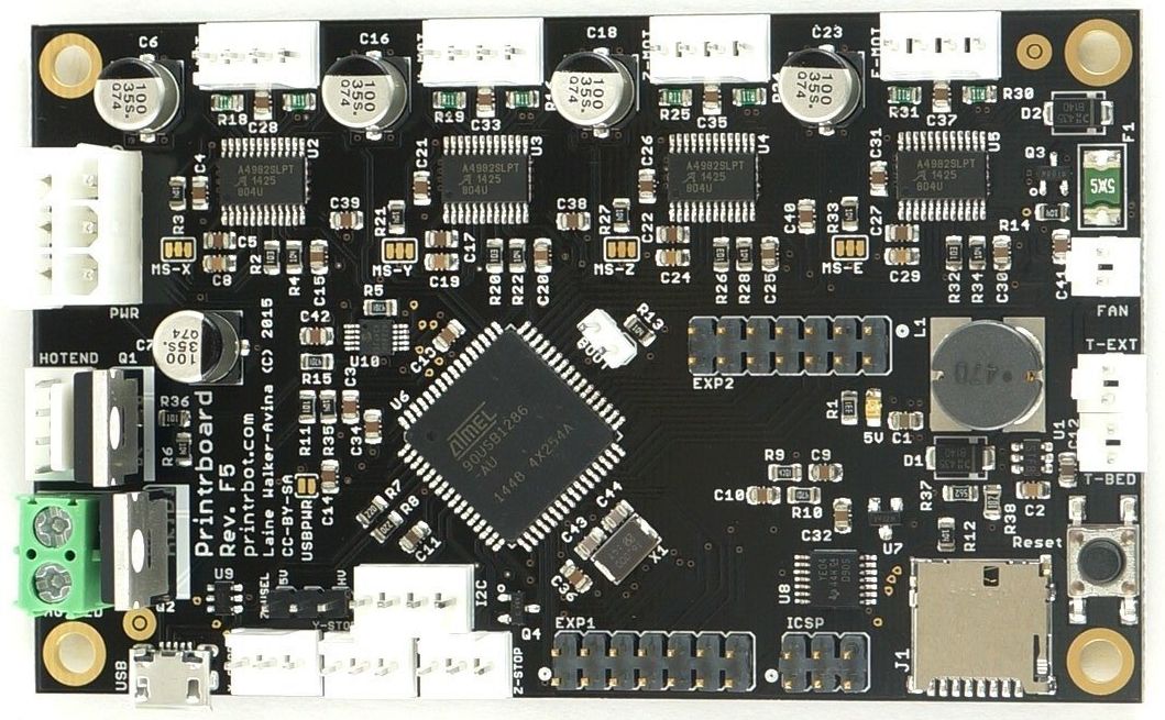
PrintrBoard REV F
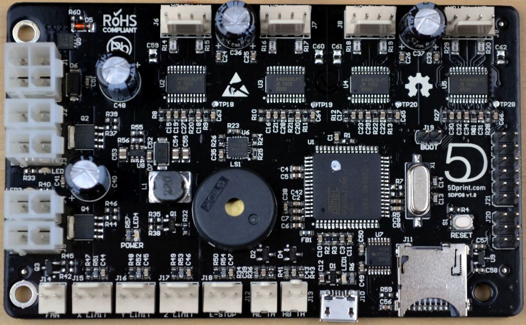
PrintrBoard REV F4

PrintrBoard REV F5
Revision History
- RevA [January 2012]: Internal pre-production design.
- RevB [February 2012]: First release to manufacturing (RTM), built for first batch of Printrbots. Each stepper driver IC utilizes an SMT solder jumper, MS-X, MS-Y, MS-Z, MS-E to set the microstepping ratio. These jumpers are manually soldered in production and will be eliminated in future batches.
- RevC [April 2012]: (Non-Printrbot Release) Fixed manufacturability of SMT solder jumpers, MS-X, MS-Y, MS-Z, MS-E. Fixed “printrbot” logo on bottom silkscreen.
- RevD [June 2012]: Made some more fixes for manufacturability and usability. Also changed the polarity of the BOOT jumper so that the jumper is required only when going into bootloader mode.
- RevE [July 2012]: (Non-Printrbot release) MOSFET’s changed to 70A smt version.
- RevF [Winter 2013]: Changed heatbed connector to 5mm pitch screw terminal, Removed E-STOP connector, Changed Y-STOP pin, Moved former Y-STOP pin to SD interface to fix a limitation of the SPI module, Added I2C connector, Replaced trimpots with 4-channel I2C DAC, Added polyfuse and reverse protection diode to fan circuit, Added more empty space around fan connector, Made ICSP and EXP1 connector pins share a 0.1″ grid, Removed reset signal from EXP1, and replaced it with GPIO, Changed input PWR connector to a 6-pin one from the same family, Removed stop layer from several vias for future bed-of-nails tester, Change to through-hole mount microUSB connector, Added USB TVS diode pack to protect USB controller from ESD
- RevF4 [July 2014] Added in voltage selection and input buffering for the Z-stop.
Interface specifications
1. 2 channel ADC interface for thermometry: one for Extruder and another for Heatbed.
2. 3 channel PWM: one for extruder control, one for heatbed and one for fan.
3. 4 channel endstop: for x/y/z/e separately to connect to mechanical or optic endstop or hall sensor.
4. With TF card slot which supports 8G <= FAT16 and FAT32.
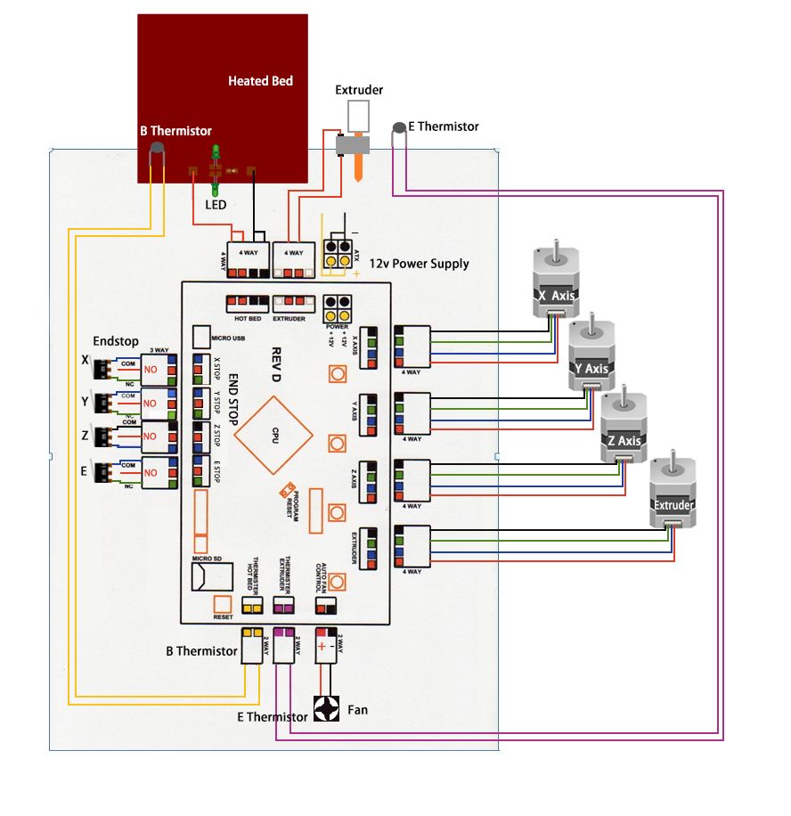
Stepper Motors
Connect the X, Y, Z axis, and extruder motors to the matching headers at the top of the Printrboard (X-MOT, Y-MOT, Z-MOT, E-MOT). Crimp housings are 4 wire Molex KK series, part# 0022013047) with 2759 series crimp terminals, part# 0008550101.
Motor pinout is:
| A4982 Driver Pin | LP Pkg Pin Name | Phase | Header Pin |
|---|---|---|---|
| 22 | OUT2B | Phase 2- | 1 (the square one on the PCB) |
| 19 | OUT2A | Phase 2+ | 2 |
| 18 | OUT1A | Phase 1+ | 3 |
| 15 | OUT1B | Phase 1- | 4 |
Note: PrintrBot Simple Metal Plus swaps phases 1 and 2, and their polarities, on the X-axis, by attaching the crimp housing and wires with its ends swapped. Alternatively, if the crimp housing is attached with the same orientation as the other axes, wires from either phase (but not both) can be swapped to achieve the same effect.
Endstops
Usually, one connects a mechanical microswitch to each of the 3-pin Molex headers X-STOP, Y-STOP, Z-STOP at the bottom of the board. The E-STOP header is reserved for future use, but might be treated as an emergency stop by some firmware.
Connect switches as follows:
- Switch NC (Normally Closed contact)
- No connection (this is +5v out, and not used in this configuration)
- Switch COMMON contact
For typical optos, connect:
- Signal Output (from the sensor, back to the Printrboard)
- +5V (provides power to the sensor)
- GND (Ground)
Z-Stop on Rev F4:
- Signal Input from sensor (for induction sensors like Printrbot’s auto-level sensor, this will be +5 or +12V, depending on jumper selection, when triggered)
- +5V or +12V, depending on jumper selection on board
- GND
Heaters
Connect the heating element of your hotend (resistor or nichrome wire) to the 4-pin EXTRUDER header, positioned next to MOSFET Q1. Connect your heatbed to the HOTBED header, next to MOSFET Q2. Polarity here is unimportant.
pinout is as follows:
- Positive
- Positive
- Negative
- Negative
Note: The above “pinout” description seems incorrect. Pin 1 is the square pin. Pins 3 and 4 are both +12v power. Pins 1 and 2 are the control to the Hotend and are pulled to ground by the MOSFET, closing the circuit (12v Power through Hotend to Ground), turning the Hotend ON. The pairs of pins (1 and 2 together, and 3 and 4 together) are used to better conduct the high currents required of these “Hot” devices. The Hotbed operates the same way, with the same pinout, from the connector closer to the corner of the Printrboard.
Thermistors
Thermistor headers are 2-pin Molex headers at the right side of the board, located above the reset button.
Connect the heatbed thermistor to the header directly above the reset button. The hotend thermistor connects above the heatbed header.
Lower Power Fan
A 2-pin Molex header labelled FAN is located on the right side of the board, above the thermistor headers. This optional header can be used to power a fan or other small motor. One pin is the +12v supply, and the other is the ON control, pulled to ground whenever the fan should be ON. Generally not used, but some firmware can control this “fan”, I believe.
Board Power
Normally, all power is supplied through the 6-pin (3×2, “PCIe”) ATX style header on the left edge, near the upper left corner of the Printrboard, labelled PWR. Before revision F, this was a 4-pin (2×2, “P4”) ATX-style header. Connect this Power Input directly to any 12VDC power supply of sufficient amperage capability to run the intended devices. For example using a 120 watt hotbed would use 10 amps, all by itself, and more when it is first turned on. The two Ground terminals are closest to the edge of the board (left), and the two 12VDC+ terminals are away from the edge (at the right).
The USBPWR “solder-jumper” is located about half way between the large square micro-processor chip and the two 4-pin connectors for the Hotbed and “extruder”. Normally open, it is only used (connected) when it is necessary to use the USB input to supply the Printrboard’s Logic with +5v power (when the 12v power input is not being used). Usually, the +5v for the board’s logic is supplied by a regulator that is powered by the 12v input, and the open jumper keeps the board’s 5v from feeding back into the USB connection.
USB
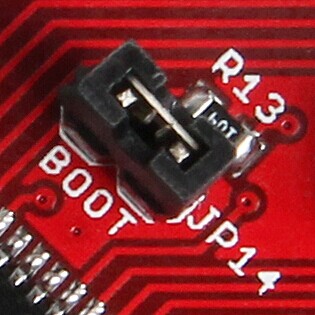
Connect a micro-USB cable to the USB jack at the bottom of the PCB. Note that a jumper should be installed on the “BOOT” pins for normal operation (see Printrboard#Bootloaders). In revision D, the behavior was inverted so that the jumper is only need when using the bootloader.
Jumper Instruction
NOTE: do remember to put on the jumper cap. Or it will affect the uploading of firmware and the connection with PC.
Get Started – Marlin firmware
Printrboard is the CPU of a 3D printer, manipulating the whole process of printing. Printrboard can’t be put in use directly without uploading firmware. 1. Firmware uploading- marlin.
2. Setting parameters of the firmware
The parameters that need setting are as below, for those not mentioned just leave them as default.
|
1 |
#define BAUDRATE 250000 |
This parameter is for the baud rate of serial port. Note: a successful communication can be realized only when the Baud rate of upper computer is identical with that of Firmware. The Baud rate is not set in random. The common Baud rate are: 2400,9600,19200,38400,57600,115200,250000. The last three are frequently used for 3D Printer.
|
1 |
#define MOTHERBOARD 81 |
This parameter is set for board type. 3D Printer has many types of main board, and the settings of IOs are different, therefore, the parameter has to correspond to the type of your board, or it can’t operate normally. The parameter of Printrboard should be 81(single- nozzle). For other board, you can refer to the annotation on the board.
|
1 2 |
#define TEMP_SENSOR_0 3 #define TEMP_SENSOR_BED 3 |
The two parameters are set for the type of temperature sensor respectively. They are the critical parameter to check if the sensor read temperature correctly. The printer can’t operate normally, even has potential risk (damage the device and even worse). You must modify depending on the temperature sensor you use.
#define EXTRUDE_MINTEMP 170
This parameter is set to avoid potential risks when the extruder operates before reaching the rated temperature. If you use other 3D Printer, such as printer to make Chocolates, 45℃ is appropriate, so that the parameter configured to a lower value(such as 40℃).
|
1 2 3 |
const bool X_ENDSTOPS_INVERTING = true; const bool Y_ENDSTOPS_INVERTING = true; const bool Z_ENDSTOPS_INVERTING = true. |
The three parameters are set for the end stops of three axes. If the configuration is true, the end stop outputs 1 in default condition, and outputs 0 when triggered. That is to say, mechanical end stop should connect to the NO (normally open) contactor. If it is connected to the NC (normally closed), true should be changed to false.
|
1 2 |
#define INVERT_X_DIR false #define INVERT_Y_DIR true |
Mistakes are often made in the above two parameters. The parameters are different for different machinery. In principle, the origin should be at lower-left corner of the print platform (origin: [0, 0]), or at up-right corner (origin: [max, max]). Only in this way will the printing be correct, otherwise, the printing is the mirror image of one axis which is not what expected.
|
1 2 3 |
#define X_HOME_DIR -1 #define Y_HOME_DIR -1 #define Z_HOME_DIR -1 |
If the position of the origin is the minimum, the parameter is -1; if it is the maximum, the parameter is 1.
|
1 2 3 4 5 6 |
#define X_MAX_POS 205 #define X_MIN_POS 0 #define Y_MAX_POS 205 #define Y_MIN_POS 0 #define Z_MAX_POS 200 #define Z_MIN_POS 0 |
These parameters are crucial to the printing size. Fill in parameters by reference to the coordinate graphs. It is important to note that the origin is not the printing center and the real printing center usually lies at [(x.max – x.min)/2, (y.max -y.min/2)]. The coordinate of central will be used in the slice tool. The printing center’s coordinate must correspond to the parameter configuration, or it will print to the outside of the platform.
#define HOMING_FEEDRATE {50*60, 50*60, 4*60, 0}
The parameter means the homing speeds (mm/min). This parameter can be set as default if you use the x-axis and y-axis adopt synchronous belt drive and z-axis adopts screw drive.
#define DEFAULT_AXIS_STEPS_PER_UNIT {85.3333, 85.3333, 2560, 158.8308}
These parameters are crucial to the printing size. These parameters indicate the pulse the axis need when operating 1mm. they are corresponding to x, y, z axis and extruder respectively. In most cases these figure should be calculated by yourself, you can refer to: http://calculator.josefprusa.cz/#steppers.
So far, the commonest parameters have been configured and the printer can work now. In addition, if the 2004 LCD needs verifying, you should delete the “//” from “//#define REPRAP_DISCOUNT_SMART_CONTROLLER” to ensure the normal working.
Bronnen:
reprap.org
geeetech.com