Mechanica Hardware – Sanguinololu board
![]()
Informatie (ENG):
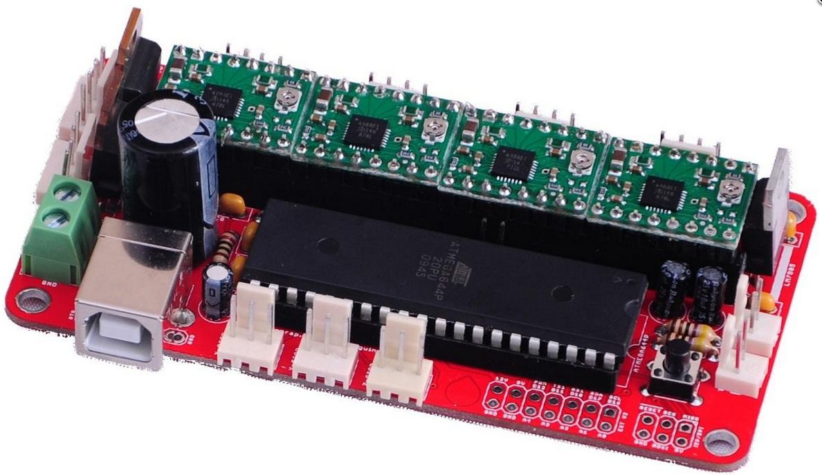
Sanguinololu is a low-cost all-in-one electronics solution for Reprap and other CNC devices. It features an onboard Sanguino clone using the ATMEGA644P though a ATMEGA1284 is easily dropped in. Its four axes are powered by Pololu pin compatible stepper drivers.
The board features a developer friendly expansion port supporting I2C, SPI, UART, as well as a few ADC pins. All 14 expansion pins can be used as GPIO as well.
It is capable of 4 axis (X,Y,Z, Extruder), heated bed control, hot-end control, homing switches, and LCD screen control. It is a very popular board to use in the 3D-Printing community
The board is designed to be flexible in the user’s power source availability, allowing for an ATX power supply to power the board, or the user can choose to install the voltage regulator kit for use with any power supply 7V-30V.
Features
-
- Small design — board is 100mm x 50mm (4″ x 2″) — barely an inch longer than a business card
- Sanguino clone, Atmel ATmega644P — ATmega1284 drop-in compatible
- 4 Pololu stepper driver boards (or Pololu compatible) on-board (X,Y,Z,Extruder)
- Supports multiple power configurations
- — Logic and motors supplied by ATX power supply
- — Motors supplied by 5mm screw terminal 7-35V
- — Logic supplied by USB
- — Logic supplied by on-board voltage regulator
-
- Supports multiple communication configurations
- — FT232RL on-board for USB connectivity
- — USB2TTL header is available for FTDI cable or BlueSMIRF bluetooth module
-
- 2 thermistor connectors with circuitry
- 2 N-MOSFETs for extruder/heated bed
- Selectable 12v(or supply voltage)/5v endstop voltage
- Edge connectors enabling right-angle connections
- Silkscreen for connectors on both sides of the board, facilitating bottom cable connections
- 13 extra pins available for expansion and development — 6 analog and 8 digital, with the following capabilities
- — UART1 (RX and TX)
- — I2C (SDA and SCL)
- — SPI (MOSI, MISO, SCK)
- — PWM pin (1)
- — Analog I/O (5)
-
- All through-hole components (except FTDI chip) for easy DIY soldering
Bugs
- The USB 5V VBUS is connected to the output of the 5V regulator. This is bad for the regulator and bad for the PC. Some users report the regulator getting very hot (because it is trying to power the PC), other users report the PC giving USB over current errors. Nophead and Nothinman recommend cutting the 5V track to the USB connector. The only downside is the board needs the 12V supply before it will do anything, but who cares?
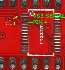
- An alternate fix for the 1.3a board is to cut the trace between the USB chip pin 4 and C13. This is functionally identical to building a Sanguinololu without the USB port and FT232RL and using an offboard USB-serial cable. The advantage over cutting the 5V trace at the USB connector is that the USB serial port doesn’t disappear from the host PC when the printer is switched off, which can anger host software that is still running.
- Another fix that seems to work using Schottky diodes: http://forums.reprap.org/read.php?158,400825
- Another fix is to strip the insulation and shield from the USB cable and cut the 5V wire. This has the advantages that, if the board is powered off, another cable with all wires intact can be used to communicate with the board and it does not require a board modification. The 5V wire can be identified by searching for USB pinouts and can be checked by sticking a needle through the wire insulation to measure conductivity.
- When the bootstrap loader runs during reset and when downloading firmware the motors are enabled due to pull-downs on the Pololus (The enable pins are pulled up by 100K resistors on the Sanguinololu but they are pulled down by 100K on each Pololu). The step pins are floating and this can cause random motor movements. The E step pin is next to E dir pin which the bootstrap thinks is an LED to be flashed. Crosstalk can cause the extruder to spin when firmware is being loaded. This is not good as it will be cold, so could damage the hot end. Nophead recommends changing the enable line pull ups (R7 and R8) to 4K7 to ensure the motors are disabled until the firmware enables them.
- A software fix is to use the the Gen7 boot strap that does not flash the non-existent LED.
- The pads and traces on the board are not robust enough to handle the high current involved when controlling the heated bed with the sanguinololu’s dedicated mosfet. If left as is, the board will heat up in this area, could be damaged and the plastic connectors discolored. To fix, simply add a direct current path by way of (preferably insulated) wire from the 12v input to the 12v pins on the Heated Bed (HB) connector; from the center pin of the HB mosfet to the two ground pins on the HB connector; and from the ground pin on the mosfet to the ground input of the board (probably the ground side of the 12v connector). Find the appropriate traces using continuity check or resistance mode on your multimeter, and check after to ensure you didn’t create a short between any of these components in the process. It would be prudent to check for shorts before starting so you don’t waste effort trying to fix a short you think you just created but was already there before you applied this fix. To understand this fix, pretend that no traces exist between the high current pathways of the 12v input and 12v pins of the HB connector; the ground input and the ground pin on the mosfet, and the center pin of the mosfet and ground pins on the HB connector. Assume you must create these pathways, then do so!
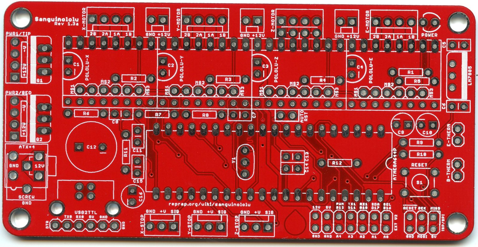
Sanguinololu Rev 1.3a

Rev 1.3a Version 1.3a has no firmware changes — the pin assignments remain the same and v1.2-compatible firmware should work fine. The hardware changes:
- Removed the Molex HDD connector in favor of using the voltage regulator – some power supplies give a dirty 5V signal when there is no motherboard load, so it’s better to just use the power supply’s ATX+4 connector and the 5V voltage regulator.
- Added a jumper to enable/disable USB auto-reset. This way if you’re printing from an SD card using SDSL you can disconnect your USB and reconnect it without interrupting a print.
- R7 and R8 are now 100k pull-up resistors on the stepper-enable lines. This ensures the stepper motors stay disabled and don’t move while uploading new firmware, rebooting, etc. The current limiting resistors for the FTDI are gone.
- There is an extra Z-motor header for Prusa Mendel.
Er zijn ook 1.3 versies in de omloop met rechte connectors:
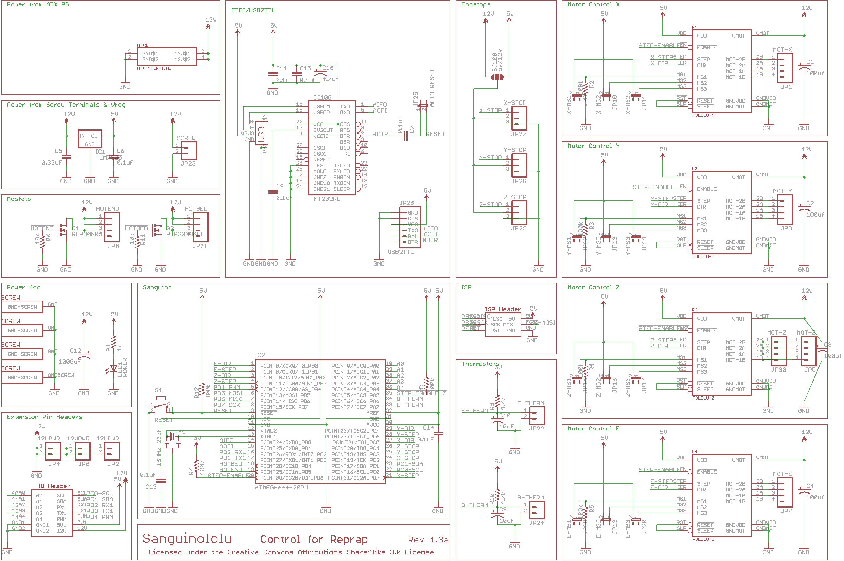
Rev 1.3a elektrisch schema:
Sanguinololu Rev 1.2
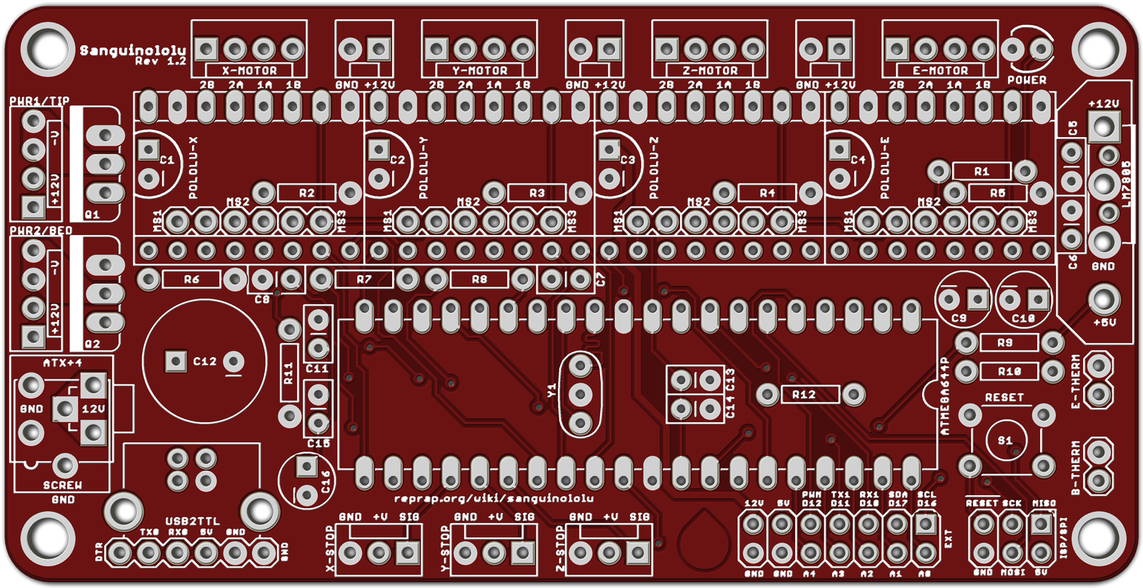
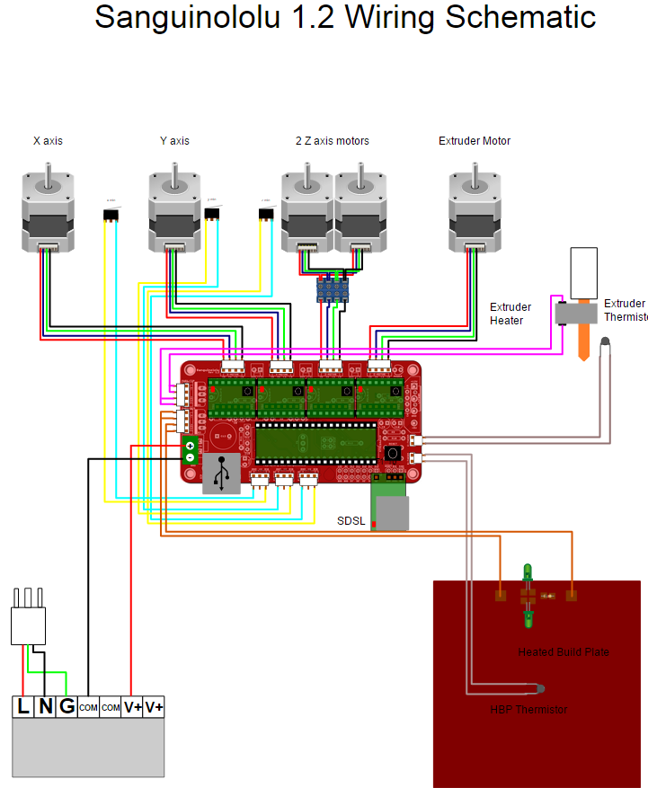
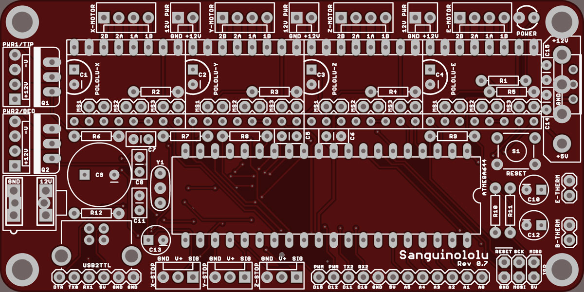
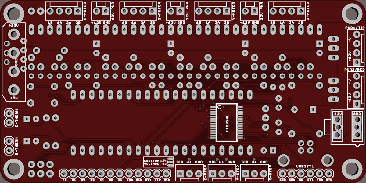
Rev 1.2 Aansluitschema (wellicht voor alle Rev’s te gebruiken)
Updated June 15, 2011.
While v1.1 is completely functional, there were some requests from users for pin assignment changes. Version 1.2 implements these firmware changes.
- Z-Enable is now on its own pin.
- PWM devices have been moved to OC0 and OC1 freeing up OC2 for internal timing.
- The expansion port is now a pin shorter — the Z-Enable feature ate an analog pin here.
Version 1.2 still includes the footprint for the Molex HDD connector, though it may be wise to disregard it and always install the 5V regulator as not all ATX power supplies’ 5V lines are stable and clean. NOTE: On the bottom side of the board, the footprint for the Molex HDD connector is backwards (beveled edges facing towards the edge of the board). Take care if soldering from the bottom side of the board to orient the HDD connector with the beveled edges facing towards the center of the board, as shown on the top side silkscreen
Sanguinololu Rev 1.1
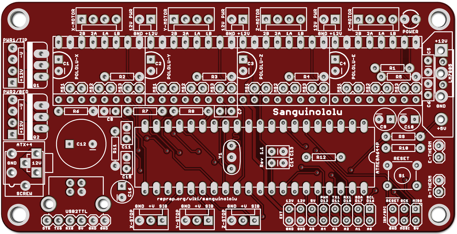
Release revision: tighter DRC rules and rotated screw terminal footprint. There is one tiny mistake on the 1.0 board: the leftmost pin on the expansion header labelled 5V is actually 12V (or supply voltage).
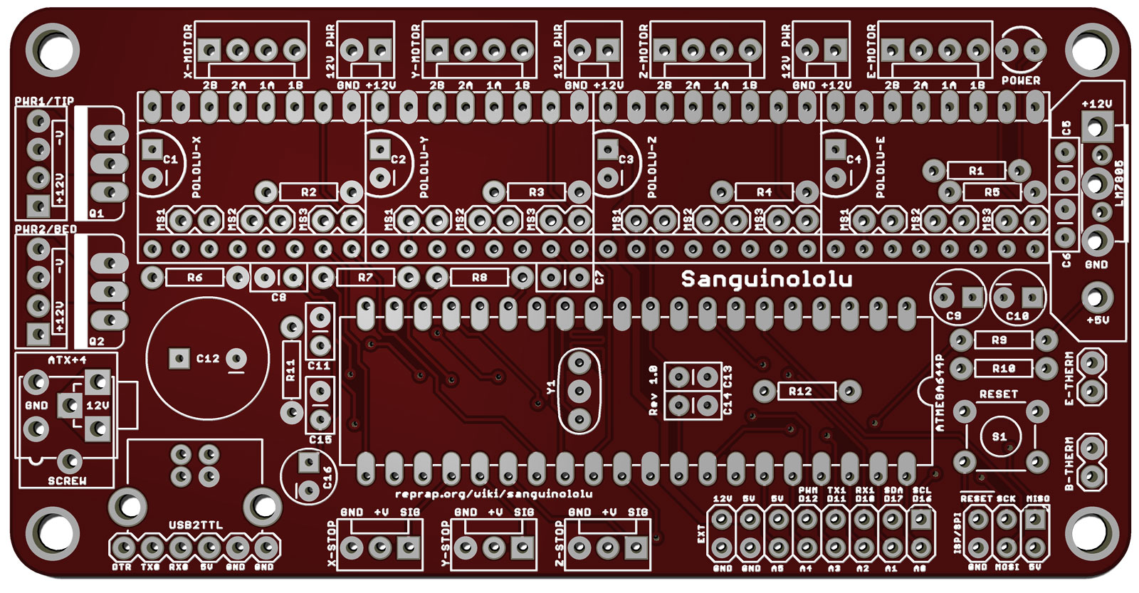
Sanguinololu Rev 1.0
Rev 1.0 elektrisch schema:
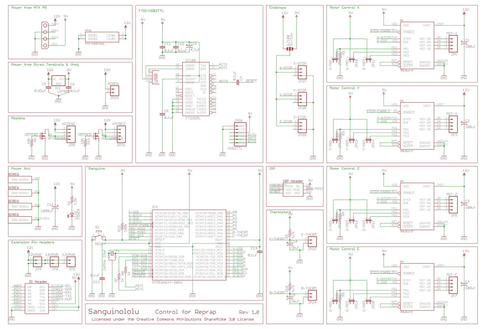
Release revision: tighter DRC rules and rotated screw terminal footprint. There is one tiny mistake on the 1.0 board: the leftmost pin on the expansion header labelled 5V is actually 12V (or supply voltage).
Sanguinololu Rev 0.7
Rev 0.7 elektrisch schema:
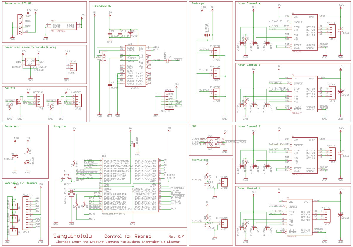
– Added more pins to the expansion header, made I2C and SPI available for use. Combined all stepper motor enable nets into one pin.
– Added footprints for voltage regulator for those wanting to use laptop power brick, etc. The vreg component footprints are hidden under the ATX power supply for space saving and to prevent both from being in use.
– Enabled USB bus power for logic side.
– Connected the 5v pin on the USB2TTL header so that either a FTDI cable can power the board or the board can power a bluetooth serial module (bluesmirf).
Sanguinololu Rev 0.3
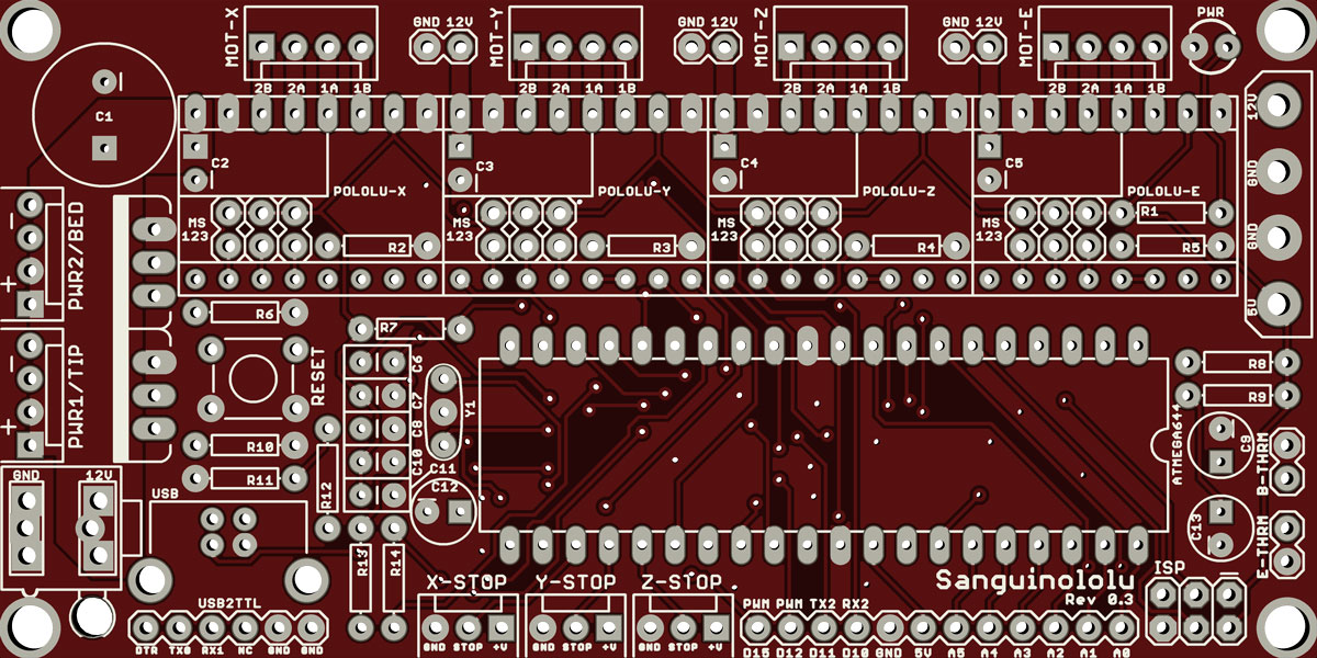
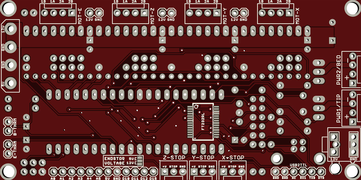
Rev 0.3 elektrisch schema:

MS1/2/3 for each motor separated. Unfortunately the best place for this to go is under the pololus, needing you to remove the pololu to change it’s microstepping settings. Oh well, I’m hoping this is a set-it-and-forget-it type of thing.
– Added optional 4-pin atx 12v connector to support large hotbed or extruder loads, up to 20A. 3A if just using the hdd connector
– Adjusted schematic to put MOSFETs gates on PWM pins for less software intense temp control.
– Moved endstop connectors to other side of board.
– Added 12V power connectors in their place, for always on fan, or whatever. Watch out for current rating. Maybe a couple of fuses is in order….
Sanguinololu Rev 0.1
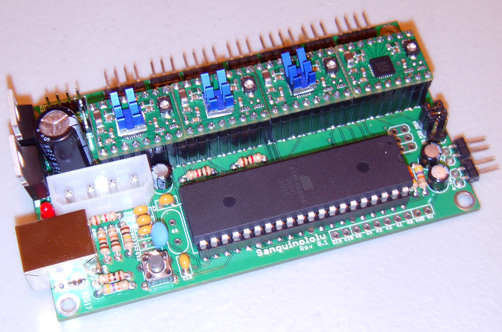
First prototype, first design, first PCB ordered, first assembled, etc