MendelMax 1 – Bouwinstructies
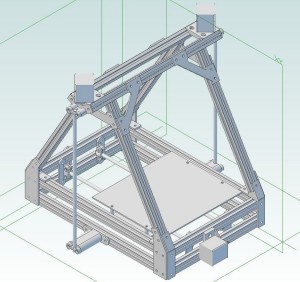
3D Printer
MendelMax 1
Bouwinstructies
My MendelMax parts arrived! Here’s my beautiful pile-o-stuff from Misumi:
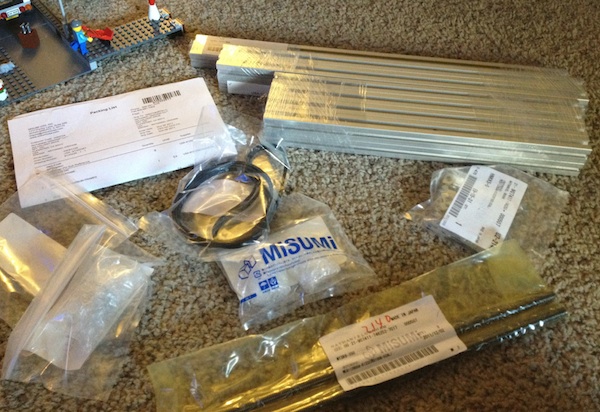
Time to get cracking! I immediately tore into it.
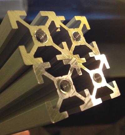
Step one is to tap the extrusions that need tapping. That means the two top extrusions (420 mm), the four diagonal extrusions which will attach directly to the lower vertices (340 mm, which only need one side tapped), and all four of the front and back extrusions on the bottom part (300 mm).
MaxBots was right, the recommended tap really did help things along. It slices into the extrusions like a hot knife through butter. I got all 16 holes tapped in about 45 minutes.
To save yourself some aggravation, for every hole you tap, screw one of your M5 screws into it and make sure that it can go in almost all the way. You want it to be able to thread in so that it’s about three or four millimeters from the aluminum. If you can’t screw it in to that point without encountering resistance, tap some more.
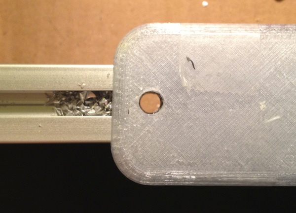
Now you need to drill into the two 420 mm extrusions that you tapped, using the printed jig to guide you. Make sure to wear goggles for this part, because, uh, having aluminum shards penetrate your eyeball is an experience most people want to avoid. My father still has a little piece of metal somewhere in his eye from a decades-ago mishap involving drills, metal, and unprotected eyes. Just do it. If you don’t have goggles, then stop and go get some, even though it’ll kill your buzz and interrupt the build. Srsly.
Next, it’s time to tap the untapped ends of the diagonal extrusions using the self-tapping screws. I bought an appropriate Torx screwdriver but found a ratcheting socket wrench with a Torx bit to be much more efficient, especially towards the end.
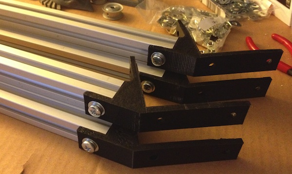
After that, you attach the first printed pieces—the lower frame vertices. The tapped end of the extrusions each get an M5 screw to connect it to the vertex. I found it fastest to first stick the screw into the hidden hole in bottom of the vertex, then attach the vertex to the extrusion with its other connection point to prevent it from rotating around, and then finally fasten the screw in the hidden hole. Do all of this four times, one for each extrusion with a self-tapping screw in one end. Don’t forget to use washers! Voila:
Now connect two of the vertices with two 300 mm extrusions, one on the top, and one on the bottom. Make sure to trap a nut in between each of them first.
Do the same for the other pair of vertices. If you’re going to support the Y axis idler on both sides rather than just one, trap two nuts in between each extrusion on this side.
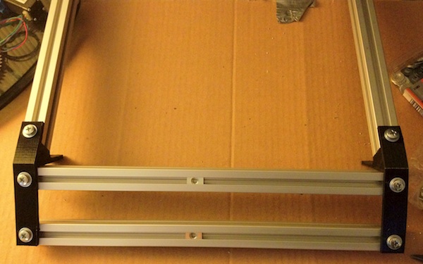
Now you want to connect these two assemblies you just made together with untapped and undrilled 420 mm extrusions, like so:
Make sure to trap two nuts in each side extrusion! At this point, it’s starting to appear more like the frame of a 3D printer. It should look like this:
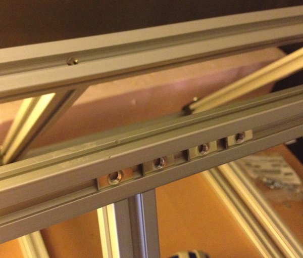
Next, you need to stick two nuts in each of the shorter 300 mm extrusions that make up the front and back. The nuts should be positioned in the interior slots so that they face one another inside the frame. These are for the interior Y rod holders.
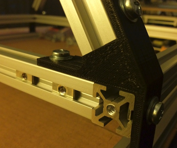
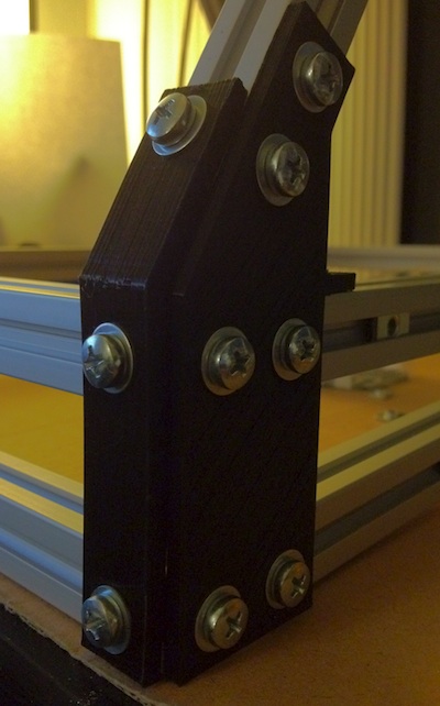
Take one of the two remaining untapped and undrilled 420 mm extrusions and stick four nuts in one side, and then position it underneath one of the already-attached 420mm extrusions with the nuts facing outwards. Do the same for the other remaining 420 mm extrusion. Now you want to attach the printed flats that connect the corner together. Use the nuts you’ve trapped in the 420 mm extrusions. For the holes that line up with the diagonal extrusion, drop two nuts down and fasten those, too. You should wind up with a corner that looks like this:
Now do the same for the other three bottom corners. Lookin’ sharp!
Now for the top. Before you attach the two remaining extrusions, drop two nuts in the each of the diagonal extrusions. They should be in the channels facing the front or back. These are for the printed diagonal stiffeners.
Slide the top 420 mm extrusions onto the diagonal ones and stick your screwdriver through the holes you drilled earlier to tighten the blind joint screws sticking out of the diagonal extrusions. Easy as pie. While you’re up there, insert four nuts into each of these top extrusions, into the front and back, respectively.
If you’re planning on using the attached spool holder, stick two nuts in the top of each of these extrusions for the spools before you attach the motor mounts. Now attach said motor mounts. They go on pretty much like you’d imagine.
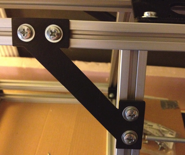
The diagonal braces also go on like you’d expect, each using four nuts you’ve trapped in the extrusions.
Almost done! Just a few more bits. First the bottom mounts for the Z smooth rods:
Then the interior holders for the Y rods:
Then the holders for the Y idler. I’m using two of them here since it seems more stable that way, but it shouldn’t be a problem if you only use one.
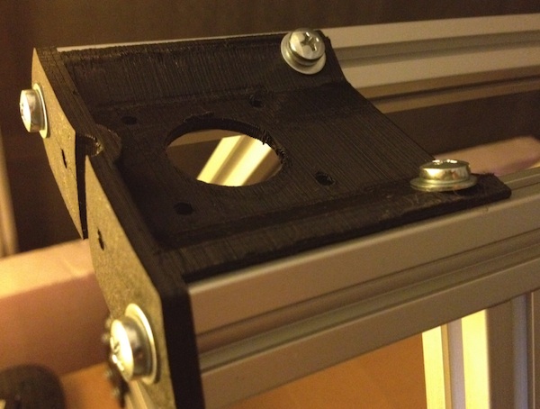
Then the Y motor holder:
And that’s a wrap. The frame is done. Total build time: 6 hours, 20 minutes. And that’s including the time it took me to write this post, which I was doing throughout the build! If I had been concentrating entire on building, it would have been closer to 3 hours.
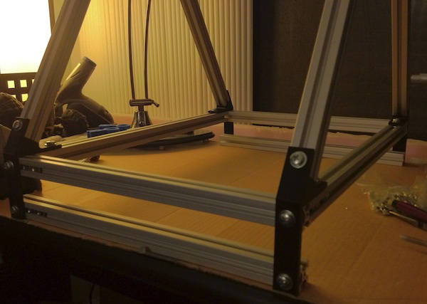
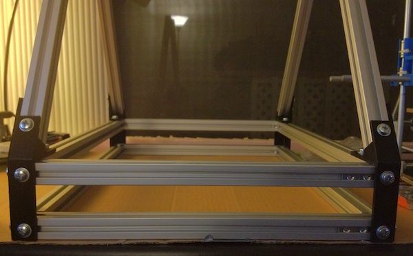
At this point I’ll mention that I scaled up my MendelMax a tad—just a tad. Instead of 300 mm long, I made the bottom extrusions 340 mm long for a little bit of extra space in the X dimension (the top ones are 460 mm). Here’s the MendelMax frame, side-by-side with my Prusa:
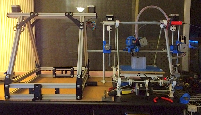
What’s also amazing is how my larger-than-normal MendelMax is actually barely bigger than my Prusa! It looks and feels larger due to the solid square aluminum extrusions and the greater volume, but objectively, The footprints are very similar. And while the Prusa looks spindly and waif-like, this thing oozes a certain tough seriousness. I’m a fan. A big fan.
MendelMax build: X and Z axes
First, assemble your X-carriage. This should be a matter of attaching whatever manner of bushing or bearing will make contact with the X smooth rods. I’m using a variant of Josef Prusa’s X-carriage I made that better supports the Igus bushings I sell:
Next, stick two of your smooth rods into one of the X-ends, either the idler holder or the motor holder, it doesn’t really matter which one. You want to be careful when inserting the rods if you’re using push-fit X-ends, as you can easily crack the whole thing if you jam the rods in too hard. You may have to ream the channel a bit or support the top and bottom when you insert the rods. Easy does it.
I’m using my X-ends that support leadscrews and Igus bushings.
Put the X-carriage onto the rods before you cap them off with the other X-end. Make sure the carriage’s two rounded protrusions are on the same side as the motor mount and the hole for the idler.
It should all look like this:
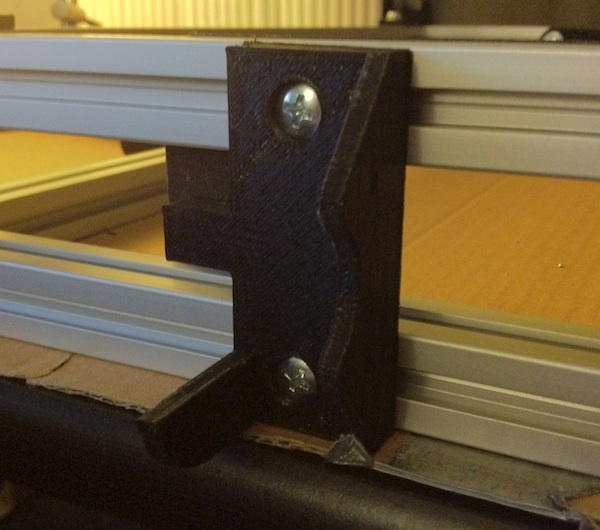
Now you need to attach to the MendelMax frame the smooth rods that these X-ends will ride on. First, attach one of the rods to the motor mount so it hangs down to the bottom:
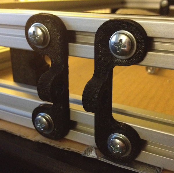
Note: those Z-rod clamps are the versions that are on the Thingiverse page; you may have newer ones that look more like this:
Now attach the lower holder and align it with the rod that’s hanging down:
Not quite there yet! You can screw the clamp right into the holes on the lower holder; no M5 nut is necessary, since this isn’t a high-stress part.
Once you’ve got the lower rod holder aligned, move the rod up a bit. Then put the completed X-gantry you assembled earlier on the frame beneath the bottom end of the rod, and line up one of the X-end’s bearing column with the rods:
Lower the rod down into the X-end’s bearing columns and tighten the clamp on the lower holder. Then do the same thing on the other side. You should have an attached X-gantry that look like this:
Make sure the gantry slides up and down smoothly, but be very careful when lifting it, as you can easily crack the X-ends’ bearing tubes at their bases. This is even more true if you happen to be using Prusa 2 LM8UU X-ends, but it’s a risk for any printed X-end. The safest way to lift the gantry is using one hand under the X rods, as close as possible to the centerline of the machine. Go slowly and if you feel resistance, let it return to the bottom while you make adjustments.
The gantry should be able to return to the bottom by gravity alone when you raise and lower it with your hand under the center of the X rods. If it binds at all, you may need to slightly adjust the position of the X-ends on their rods or move the lower Z rod holders a few millimeters to the left or right to straighten out the Z rods.
Once the gantry slides up and down smoothly, it’s time to insert the leadscrews! First thread a leadscrew into the X-ends. Make sure the top end is a little beneath the hole in the motor mount.
Attach one of your aluminum couplers to a motor. Tighten the lower set screws to join it to the motor shaft, but make sure that the upper set screws are loosened enough not to obstruct the leadscrew when you insert it.
…and then put the motor onto the mount, letting the leadscrew enter the coupler’s larger hole:
Tighten the remaining set screws to attach the leadscrew to the coupler. Keep in mind here that doing so will slightly deform the metal of the leadscrews where the set screws dig in. DO NOT attach a leadscrew to the clamp at one end, and then change your mind and clamp it at the other end instead, because the first end will have deformed threads and it won’t go through its nut. You don’t want that.
Finally, screw the motor to its mount. Even though there are four holes, you really only need to attach the motor with two screws.
Now do all the same things for the other leadscrew and motor. Once the leadscrews are attached and the motors fastened to their holders, rotate both leadscrew shafts to bring the X-gantry up towards the top of the frame. This will take it up out of the way so you can later assemble the Y axis easily. You should wind up with this:
Congratulations! It’s getting closer… now time for the Y-table!
MendelMax build: Y table
Time to move onto the Y-table. A huge X-Y build area is one of the big advantages of the MendelMax, so this is a fun process.
Before you do anything, insert your bushings into their holders. This will depend on your bushings and your holders, but I’m using Igus bushings and my Igus bushing holders.
Now stick these bushings-in-their-holders onto their Y-rods (two per rod). Fasten the rods to the sides of the Y-rod holders using printed clamps secured with M5 screws, screwing them into M5 nuts in the built-in nut holders. I found that screws longer than 10 mm helped here, so I pulled out some 16 mm long M5 screws that work perfectly.
The actual Y-table itself will really vary from machine to machine. Heated build platform choices, bushing choices, basic structure, etc. I’m going to go with a fairly conventional approach of a bottom plate of MDF that the bushing holders and belts are attached to, which itself is attached to an MDF print bed. I’m not using a heated build platform, but this setup gives me the flexibility to add one in the future by simply attaching it to the print bed.
I cut a 290 mm x 290 mm square of MDF to serve as the print bed and a 290 mm x 100 mm rectangle to serve as the bottom sheet. Now, my MendelMax is 40 mm wider than the “standard” size so all the lengths here reflect that. If you’re building a standard-sized machine, the print bed should be more like 250 x 290 and the bottom sheet should be 250 x 100. Measure your machine to make sure the dimensions make sense.
Now you need to drill holes in the bottom sheet to attach the bushing holders. Take the bushing holders you already attached to the rods and press them against the bottom sheet, moving the sheet until you have it positioned right. Then use a pencil and blacken the MDF visible through the screw holes in the bushing holders. Then go off and drill those holes to accommodate M3 screws.
Attach this drilled bottom sheet to your bushing holders and tighten the holders down:
Slide the carriage along the rods and push it sharply and see if its momentum continues the movement for a bit. If it doesn’t, then the bushings are binding somewhere and you’ll need to slightly reposition the holders. I found that enlarging or extending the drilled holes using a dremel tool allowed enough wiggle room that I could position the holders in such a way that there was no binding. Once you have this done, tighten the holders down in their new positions. Again make sure the carriage slides smoothly and keeps moving a bit after you stop pushing. If not, then continue this process of slightly repositioning the bushing holders until you get it perfect. You really want the Y-table to be as close to frictionless as you can manage.
Now we need to drill holes at the corners of this bottom sheet where it will connect to the actual print bed. I like to remove the bottom sheet, duct tape it to the print bed, and drill both at the same time so I can be sure the holes will line up:
Now’s the time to mark on your bottom sheet where to drill holes for the belt clamps. You want the belt clamps to be directly in front of the motor and idler pulleys when the carriage is slid all the way up or down the rods. I like to place the actual clamps in place and use a pencil to blacken the MDF visible through their holes. It’s not a disaster if they’re not perfectly centered since you can simply slide the motor and idler mounts along their extrusions to center them with wherever you put the belt clamps.
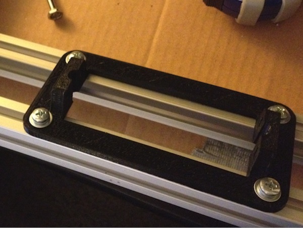
After drilling the holes, attach the belt clamps and their nut holders on the other side with washers and M3 screws that are at least 20 mm long:
Now you want to attach the bottom sheet to the print bed. There are several schools of thought on the best way to accomplish this, but I’m going with the tried-and-true screws-and-springs method. The upside to this method is that leveling the bed is incredibly easy, but the downside is that if you have weak springs, the bed can wobble and vibrate as the bottom sheet slides along the rods at high speed. To alleviate this, and to work around the fact that I didn’t have anything super-powerful in my big box ‘o springs, I used three of them for each 45mm long M3 screw:
Fasten the bottom sheet to the print bed with M3 nuts and washers. Don’t worry about tightening them all the way down or leveling it yet; we’ll do that later. Once you do, with all those springs, there’s so much tension that the print bed will be rock solid! Here’s what your completed bed should look like:
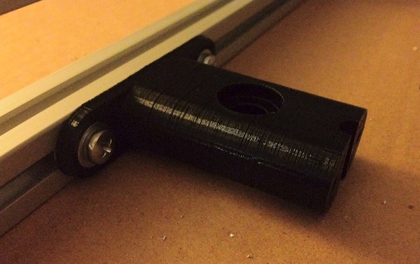
Now let’s deal with the Y-axis motor and idler mounts. I used a spare M8 bolt I had lying around for the idler, but you could easily use a 50 mm length of M8 threaded rod. Put two 608 bearings on your rod with washers on either side and tighten it down with M8 nuts. The dual 608 bearings are important because they prevent each other from wobbling. A single 608 bearing will eventually wobble and make the belt collide with the side of the idler mount.
Center the idler mechanism so that the bearings are right in front of the carriage’s belt clamp and tighten down the M5 nuts holding it to the extrusions. Note: this is the older-style idler mount; your idler may be the newer improvement made by AlephObjects, in which case it will function exactly the same way but look like this:
Time for the motor mount. Attach the motor with M3 screws that are 10-12 mm long and two washers. Then attach your motor pulley; I’m using metal ones from Misumi which are pricy but nice. Like with the idler, move the mount to center the motor pulley at the belt clamp on the bottom sheet and then tighten it down.
Almost done! Now comes the final step: attaching the belt. This part is a little tricky without access to the underside of the machine, so I balanced it on two kitchen table chairs to allow me to work from below.
You’ll want to take one end of your belt (I’m using 2mm GT2 belts) and fasten it to the idler-side belt clamp by loosening the clamp, inserting the belt, and tightening it back up again. Then thread the belt around the idler:
Now do the same on the motor side. Take the loose end of the belt, loop it around the motor pulley, attach it to the clamp on the other side. Pull it as tight as you can! You can cut off the loose ends to prevent the rest of the belt from flopping around. Here’s what it looks like on the bottom:
And from the top:
Slide the table around and let your imagination go wild as you think of all the 280 mm long objects you’ll soon be able to print! Next up: the extruder.
MendelMax build: extruder
We’re nearing the end of the mechanical parts! I’ll be using the popular Greg’s Hinged Accessible Extruder in this guide. This section may differ for you if you’re using an alternate extruder such as the venerable Wade’s, but they’re all broadly similar.
Let’s start with the idler. You’ll need to put a 608 bearing onto a 20 mm segment of M8 rod, and then insert that into the idler body:
I’ve used a threaded rod here, but a smooth rod should be perfect as well; it really makes no difference. You also need to insert an M3 nut into the nut trap in the idler’s hinge. That’s what keeps the hinge screw from falling out. I know, right? It’s pretty clever!
Clean up the extruder body before putting the idler on. This basically entails drilling the holes that were used as bridges. Then stick the idler onto the extruder body and fasten it with an M3 screw. A 25mm long screw is perfect; any longer and it’ll interfere with the large gear. A washer is optional since this screw isn’t really load-bearing, but I think it looks nice. You should wind up with this:
Stick two 608 bearings in the 608 bearing-shaped cutouts on either side of the extruder body. Now it’s time to insert your hobbed bolt and attach fasten it to the large gear. Depending on the positioning of the hobbling, the bolt’s head may be on the gear or the other side. Test its positioning and add M8 washers on the appropriate side if the hobbling doesn’t align perfectly. Make sure there’s an M8 washer between the 608 bearing and the large gear. Once you’re satisfied with the bolt’s positioning, it’s time to screw everything down. If the gear winds up with an M8 nut connecting it to the hobbed bolt, lock that nut against another one to prevent it from rotating independently from the bolt.
Next, you want to fasten the idler to the body. Assuming you use a strong enough spring, you only really need one screw. I found that a 45 mm long M3 screw was the perfect length. Put a washer on the end of the screw and stick a spring up against it, then put another washer on the other side of the spring. Drop an M3 nut into one of the nut traps, put the assembled screw-and-spring through one of the holes in the idler, and screw it into the embedded nut. You should wind up with this:
Time for the motor. Take the small gear and stick an M3 nut into the nut trap, then screw in an M3 set screw:
Stick the gear on the motor shaft with its now-embedded set screw pointing at the shaft’s flat part (if it has one), but don’t tighten down the set screw just yet. You may need to adjust the gear’s position up or down the shaft a bit to ensure that its teeth match up with those of the big gear.
Now you want to mount the motor to the extruder body. Use 12 mm M3 screws and washers, and adjust the positioning so that the gears’ teeth mesh snugly. When you have the motor fastened down, tighten the small gear’s set screw to make sure it doesn’t go anywhere!
Now mount the hot end. How you do this depends on your choice of hot end, but most of them will use a wooden, acrylic, or printed bracket to connect to the extruder. The J-head I know is simply stuck right into the hole in the bottom and fastened with screws, which is even easier.
I’m using a MakerGear extruder with the wooden mounting pieces. Now, unfortunately my wooden pieces didn’t come with the holes drilled in quite the right places, so I had to open them up with a dremel tool a bit. Yours might not suffer from this issue; YMMV. In any event, attach your hot end to the mounting piece and then stick the mounting piece onto the extruder, if your hot end so requires.
Insert M4 nuts into the nut traps at the bottom of the extruder:
Now attach the extruder to the carriage with M4 screws, inserted up through the bottom of the X-carriage. Some carriages—including the standard Prusa carriage—may need the holes drilled out to M4 size since they’re for M3 screws by default. If your hot end has a mounting bracket, the M4 screw should go through the mounting bracket as well. Here’s my completed extruder on its X-carriage:
It’s time to attach the completed extruder carriage to the belts. First, we’ll need to set up the X-axis idler and motor. Let’s start with the idler. Take a 40 mm long threaded rod and attach to it 608 bearings, washers, and nuts so it looks like this:
The large fender washer can be safely omitted if you don’t have one. I just like to put it there as extra assurance that the idler won’t eventually bow inwards. Just like with the Y axis, the dual bearings ensure that they won’t wobble and dump the belt off! That’s why you don’t even need a fender washer on the outside.
Now put the remaining pulley on your remaining motor and tighten it down as close as possible to the motor body. With large diameter pulleys like mine, it can be tough to get the belt in once the motor is attached, so loop the belt around the pulley before you attach it if that’s the case for you. Then screw the motor to the motor X-end with three 12 mm M3 screws:
At this point you can attach the loose ends of the belt to the carriage. I recommend mounting the belt clamps first and then loosening them a bit to accommodate the belt ends. The carriage has built-in nut traps, so it should be very easy to mount them with some 16 mm M3 screws and washers. Slide the carriage all the way toward the idler or motor when you’re getting ready to clamp the belt end closest to it so you can be sure the clamped end is lined up with the motor pulley or idler.
Then slide the carriage over to the other side and do the same with the other end, making sure to pull it taut before fastening the belt clamp down. Here’s the fully belted carriage:
And that’s it for the mechanical components on your MendelMax printer! Bask in the sheer badassery of your beast of a machine before you move onto the electronics.