Modbus – D/A converter – HY4AO
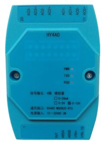
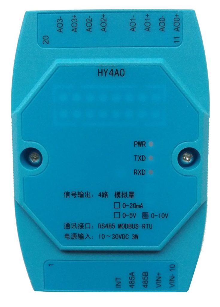
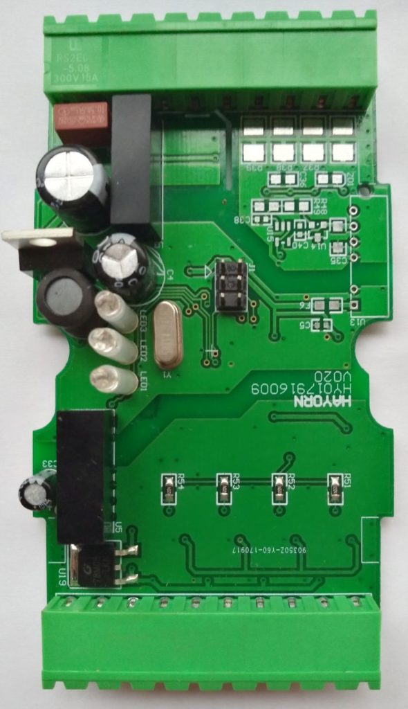
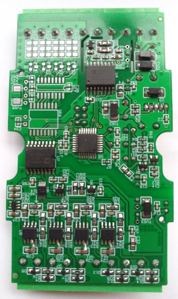
Deze Chinese D/A converter komt in meerdere modellen voor, zoals: EM4AO, HSA4O, HY4AO, etc.
Ingangsspanning is 10V met een modbus protocol kan je 4 analoge kanalen instellen van 0 ~ 10V (20mA) in 4096 stappen (12 bit).
Info (ENG)
Product Overview
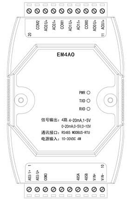
EM4AO type 4 way analog isolated output module is a universal remote I/O product in automation system. It realizes the control of 4 way analog output by RS485 communication interface.
This module for the whole industrial design, power supply, analog output, RS485 interface implementation in electrical isolated, effectively inhibit the industrial field of various string and common mode interference, to ensure the reliability and accuracy of the data. The RS485 communication interface implements the MODBUS RTU protocol, and can directly connect all kinds of PLC, DCS systems, man-machine screens and configuration software.
Product Features
- 4 analog output isolation, support 0 ~ 20mA, 4 ~ 20mA, 0 ~ 5V, 1 ~ 5V, 0 ~ 10V format
- 12-bit resolution, accuracy is better than ± 0.1%
- built-in keep the timer, improve the security of the control system
- use the write register to achieve the way the current channel and voltage channel configuration, without opening jumper settings
- full industrial design, power supply, communication, analog output isolated from each other
- With hardware to restore the communication parameters of the factory configuration function
- MODBUS RTU communication protocol
- DC10 ~ 30V wide range of power input
- maximum power consumption is only 4W
Specifications
| Current output
Voltage output |
4 current output, 12 bit resolution, accuracy + 0.1%, 0~20mA/4~20mA format
4 current output, 12 bit resolution, accuracy + 0.1%, 0~5V/1~5V/0~10V/2~10V format The writing register is used to realize the configuration of the current channel and the voltage channel without setting up the jumper wire setting Refresh cycle 2ms Built in hold time timer, holding time constant 0~60.00s Electrical isolation: 1500V (customizable 3000V) |
| communication interface | Physical type: RS485
Communication protocol: MODBUS RTU Communication rates: 1200, 2400, 4800, 9600, 19200bps With hardware force recovery, communication parameters, factory configuration function Electrical isolation: 1500V (customizable 3000V) |
| Power input | Nominal power supply: DC24V
Input range: DC10~30V Power consumption: less than 4W Protection function: anti reverse, anti surge |
| module structure | Configuration: Adam module, 10+10 bit pluggable terminals
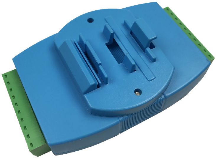
Installation: DIN rail installation |
| Outline size | Module parts: 104mm * 72mm * 26mm (excluding terminals and guide block)
Max size: 124mm * 72mm * 45mm (including terminal and guide block) |
| work environment | Operating temperature: -25 ~ +85 DEG C
Ambient humidity: 10~90%RH (without dew) |
Pinout
| terminal | Code | Name |
| 1 | AO3/I+ | Analog output 3 current channel |
| 2 | AO3/U+ | Analog output 3 voltage channel |
| 3 | AOCOM | Analog output common end |
| 4 | ||
| 5 | ||
| 6 | ||
| 7 | 485A | RS485 DATA A |
| 8 | 485B | RS485 DATA B |
| 9 | VIN+ | Power + |
| 10 | VIN- | Power – |
| 11 | AO0/I+ | Analog output 0 current channel |
| 12 | AO0/U+ | Analog output 0 voltage channel |
| 13 | AOCOM | Analog output common end |
| 14 | AO1/I+ | Analog output 1 current channel |
| 15 | AO1/U+ | Analog output 1 voltage channel |
| 16 | AOCOM | Analog output common end |
| 17 | AO2/I+ | Analog output 2 current channel |
| 18 | AO2/U+ | Analog output 2 voltage channel |
| 19 | AOCOM | Analog output common end |
| 20 |
Overige info
Indicating lamp
| Indicator light | Name | Color | Explain |
| PWR | Power indication | Green | Slow flashing: power up, Chang Liang: ready, flash: restore communication parameters |
| TXD | Data sending | Red | send data |
| RXD | Data reception | Yellow | receive data |
Force recovery communication parameters, factory configuration
When the communication parameters are forgotten or the communication parameters are changed due to misoperation, in addition to the configuration software search module, the factory configuration for forcing the resumption of communication parameters can also be carried out as follows:
(1) make sure that the module is powered off;
(2) open the module housing and plug in the short jumper cap on the 6 pin ISP connector P4-P6;
(3) the module is electrified, the module power lamp flashes slowly two times and then becomes flash;
(4) turn off the power supply and unplug the short jumper cap and close the module housing;
(5) the module is powered on, and the communication parameters of the module have been restored to:
Rate of communication: 9600bps
Check mode: no
Local address: 1
Warning: do not plug in short jumper cap before the module is powered down!!!
Foto’s
Mobus registers
Supported function code
| Code | Meaning | operation |
| 03H | Read multiple hold registers | Reads the values of one or more holding registers |
| 06H | Write a single hold register | Writes a data to a hold register |
| 10H | Write multiple hold registers | Write one or more data into a hold register |
| 11H | Read device properties | Read slave type, status |
Hold register (support function code 03H, 06H, 10H)
| address | Name | Actual value range | Bit | Range | factory
Default value |
Read / write | |
| 40001 | Communication speed | 1200/2400/4800/9600/19200 | Bit15~12 | 0,1,2,3,4 | 3 | Read / write | |
| Check mode | Parity check / parity check / odd check | Bit11~8 | 0,1,2 | 0 | |||
| Native address | 1~247 | Bit7~0 | 1~247 | 1 | |||
| 40002 | Device type | 199 | 199 | 199 | read-only | ||
| 40003 | Hardware version | H0.00~2.55 | Bit15~8 | 0~255 | read-only | ||
| Software version | R0.00~2.55 | Bit7~0 | 0~255 | ||||
| 40004 | Date of manufacture | year,year after 2 bits,2000~2099 | Bit15~9 | 0~99 | read-only | ||
| month,possision 4 bit,1~12 | Bit8~5 | 1~12 | |||||
| Day,possision 5 bit,1~31 | Bit4~0 | 1~31 | |||||
| 40005 | Production number | Production number (high byte before) | 0~65535 | read-only | |||
| 40006 | Equipment status | 0 power on (self-test) /1 ready, /2 fault | 0~2 | read-only | |||
| 40007 | Retention time constant | 0~60.00s[注1] | 0~6000 | 0 | Read write | ||
| 40008 | AO0 signal format | 0(0~20mA,0~10V)
1(0~20mA,0~5V) 2(4~20mA,2~10V)[注2] 3(4~20mA,1~5V)[注2] |
0~3 | 0 | Read write | ||
| 40009 | AO1 signal format | 0~3 | 0 | Read write | |||
| 40010 | AO2 signal format | 0~3 | 0 | Read write | |||
| 40011 | AO3 signal format | 0~3 | 0 | Read write | |||
| 40012 | AO0 preset [注3] | Analog output 0 channel | 0~4095 | 0 | Read write | ||
| 40013 | AO1 preset | Analog output 1 channel | 0~4095 | 0 | Read write | ||
| 40014 | AO2 preset | Analog output 2 channel | 0~4095 | 0 | Read write | ||
| 40015 | AO3 preset | Analog output 3 channel | 0~4095 | 0 | Read write | ||
| 40016 | AO0 given | Analog output 0 channel | 0~4095 | 0 | Read write | ||
| 40017 | AO1 given | Analog output 1 channel | 0~4095 | 0 | Read write | ||
| 40018 | AO2 given | Analog output 2 channel | 0~4095 | 0 | Read write | ||
| 40019 | AO3 given | Analog output 3 channel | 0~4095 | 0 | Read write | ||
[Note 1] Output hold constant – when 0 means that each given AO output will continue until a new given value is written. For 1 to 6000 means that if the given AO output does not update the reference again when the specified hold time is reached, the AO output will return to the initial state (ie, the preset value).
[Note 2] Signal format – When the signal format is set to 2 (4 ~ 20mA, 2 ~ 10V) or 3 (4 ~ 20mA, 1 ~ 5V), the given output will not be less than 819. If a value less than 819 is given, it is still output at the given value of 819.
[Note 3] Preset value – The static value of the output of the channel when the module is powered up or when the hold time is reached.
Device attribute register (support function code 11H)
| byte | Name | Actual value range | bit | range | Read write |
| 2 | Device type | 199 | 199 | read-only | |
| 2 | Hardware version | H0.00~2.55 | Bit15~8 | 0~255 | read-only |
| 2 | Software version | R0.00~2.55 | Bit7~0 | 0~255 | |
| 2 | Date of manufacture | year,year after 2 bits,2000~2099 | Bit15~9 | 0~99 | read-only |
| month,possision 4 bits,1~12 | Bit8~5 | 1~12 | |||
| day,possision 5 bits,1~31 | Bit4~0 | 1~31 | |||
| 2 | Production number | Production number (high byte before) | 0~65535 | read-only | |
| 2 | Equipment status | 0 power on (self-test) /1 ready, /2 fault | 0~2 | read-only | |
Voorbeeld uitlezen
Fabriek gegevens
Standaard adres: 1
Baud rate: 9600
Parity: None
Stopbits: 1
Standaard output is: 0 ~10V
|
1 2 3 4 5 6 7 8 9 10 11 12 13 14 15 16 17 18 19 20 21 22 23 24 25 26 27 28 29 30 31 32 33 34 35 36 37 38 39 40 41 42 43 44 45 46 47 48 49 50 51 52 53 |
#!/usr/bin/env python # Modbus uitlezen # Apparaat: HYA4O (DA converter) # # Script gemaakt door S. Ebeltjes (domoticx.nl) from __future__ import division import pymodbus import serial from pymodbus.pdu import ModbusRequest from pymodbus.client.sync import ModbusSerialClient as ModbusClient #initialize a serial RTU client instance from pymodbus.transaction import ModbusRtuFramer from pymodbus.constants import Endian # Nodig voor 32-bit float getallen (2 registers / 4 bytes) from pymodbus.payload import BinaryPayloadDecoder # Nodig voor 32-bit float getallen (2 registers / 4 bytes) from pymodbus.payload import BinaryPayloadBuilder # Nodig om 32-bit floats te schrijven naar register method = "rtu" port = "/dev/ttyUSB0" baudrate = 9600 stopbits = 1 bytesize = 8 parity = "N" timeout = 1 retries = 2 try: client = ModbusClient(method = method, port = port, stopbits = stopbits, bytesize = bytesize, parity = parity, baudrate = baudrate, timeout = timeout, retries = retries) connection = client.connect() except: print "Modbus connectie error / DA converter xxA4O" def a0(appid, volt): try: client.write_register(15, float(4095 / 10) * volt, unit=appid) client.close() print "Register set at:", float(4095 / 10) * volt except: print "Modbus register error (a0)" return 0 def a1(appid, volt): try: client.write_register(16, float(4095 / 10) * volt, unit=appid) client.close() print "Register set at:", float(4095 / 10) * volt except: print "Modbus register error (a1)" return 0 # Zet kanaal A0 op 5.45V a0(1, 5.45) #0-10V, decimal accepted |


