Module – Display – 1602 / 2004 LCD
Hardware
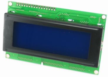
Dit zijn veelal YM2004A LCD displays, ze gebruiken en zijn gestandaardiseerd op de Hitachi HD44780 driver.
I2C controller
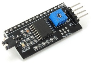
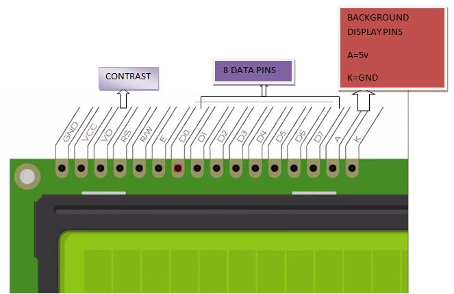
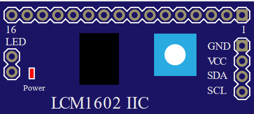
Het display heeft 16 pinnen en word parallel aangestuurd, normaliter zijn er veel aansluitingen voor nodig om het display te gebruiken, er is een HD44780 I2C converter module die je kan gebruiken om maar liefst met 4 draden het display aan te sturen:
- De Jumper (waar LED bijstaat) is voor de backlight.
- De potmeter is voor de contrastregeling.
I2C adres wijzigen
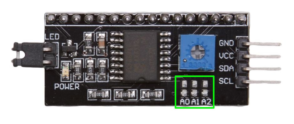
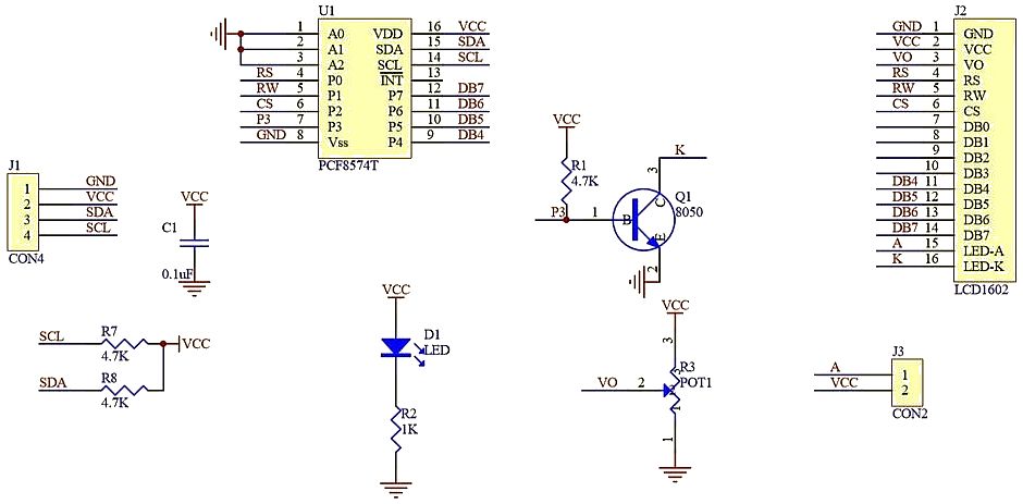
Mocht je meerdere displays of I2C apparaten willen aansluiten, dan kun je het I2C adres van de chip aanpassen, dit moet hardwarematig gebeuren door doorverbindingen te maken op de I2C print:
| I2C adres | A0 | A1 | A2 |
|---|---|---|---|
| 0x20 | 0 | 0 | 0 |
| 0x21 | 1 | 0 | 0 |
| 0x22 | 0 | 1 | 0 |
| 0x23 | 1 | 1 | 0 |
| 0x24 | 0 | 0 | 1 |
| 0x25 | 1 | 0 | 1 |
| 0x26 | 0 | 1 | 1 |
| 0x27 | 1 | 1 | 1 |
(geen doorverbinding = 1)
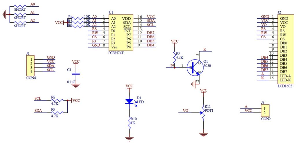
Schema:
Bronnen:
arduinoecia.com.br
hacking-arduino-and-raspberry-pi.blogspot.nl
Specifieke karakters weergeven
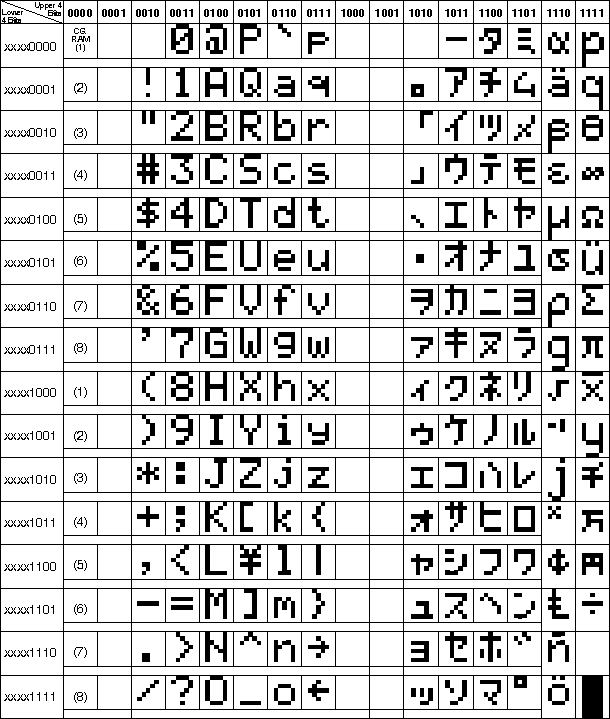
Je kan met behulp van onderstaande karakterset diverse karakters weergeven op het display, het “celcius teken” is bijvoorbeeld karakter 223 (lees uit de tabel de binaire code: 1101 1111)
Voorbeeld Arduino:
Weer te geven op het display met:
lcd.print((char)223);
Pinout
Arduino
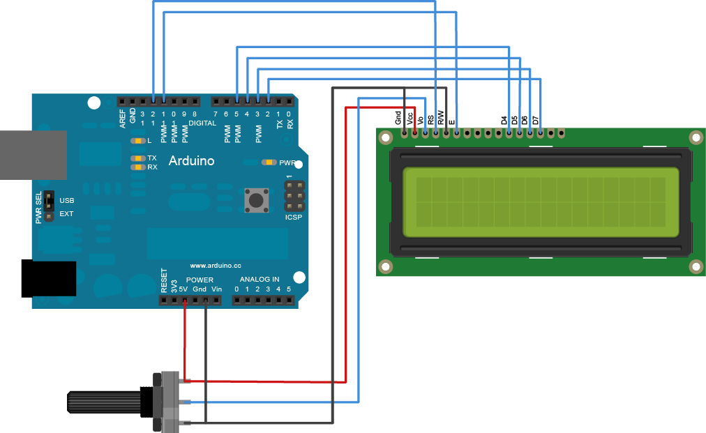
Sluit de module aan volgens onderstaand overzicht:
| Pin (van links naar rechts met het display naar boven gericht!) | Afkorting: | Omschrijving: | Arduino Pin: |
|---|---|---|---|
| 1 | VSS | Ground for logic | GND |
| 2 | VDD | +5v power supply for logic | +5v |
| 3 | V0 | Power supply for LCD drive (potmeter) | Regelbare potmeter! |
| 4 | RS | Register selection | 12 |
| 5 | R/W | Ground (to enable write to display) | GND |
| 6 | E | Enable signal for LCM | 10 |
| 11 | DB4 | Data Bus line | 5 |
| 12 | DB5 | Data Bus line | 4 |
| 13 | DB6 | Data Bus line | 3 |
| 14 | DB7 | Data Bus line | 2 |
| 15 | A | +5v for Backlight | +5v |
| 16 | K | Ground for Backlight | GND |
Scripts
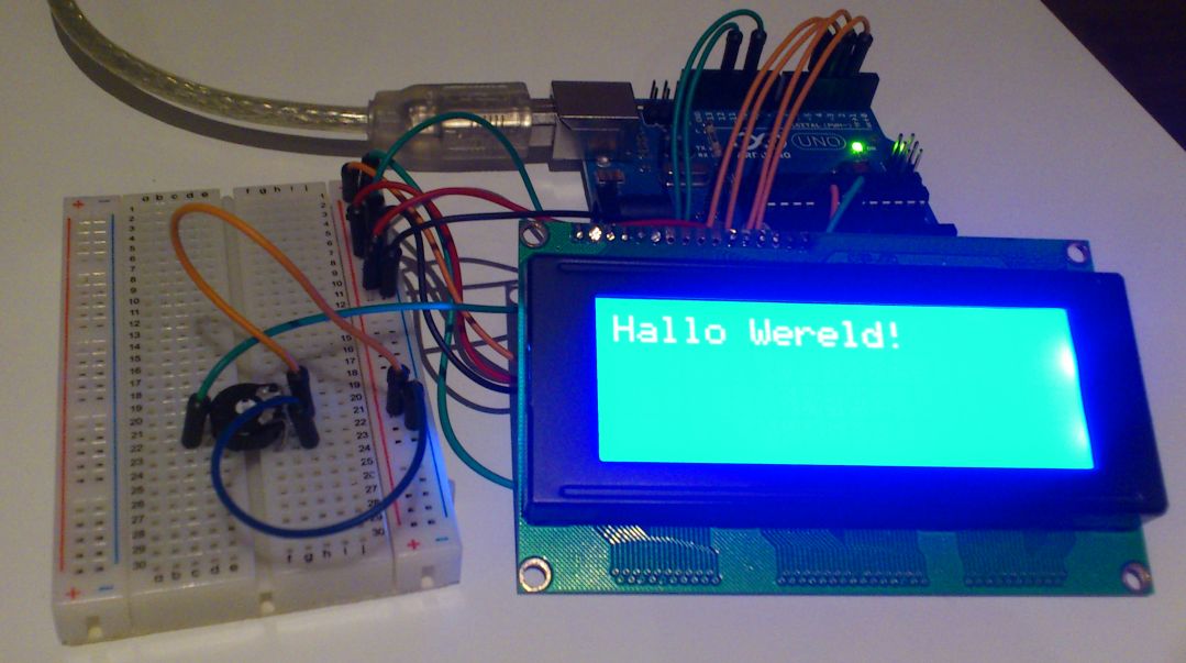
Script #1, Het script voor “Hallo wereld” icm met de “LiquidCrystal Library” (wordt standaard met arduino software meegeleverd)
Ps. vergeet niet je LCD te configureren, zoals het aantal karakters en regels dat het aankan.
|
1 2 3 4 5 6 7 8 9 10 11 12 |
#include <LiquidCrystal.h> // include the library code // initialize the library with the numbers of the interface pins LiquidCrystal lcd(12, 11, 5, 4, 3, 2); void setup() { lcd.begin(20, 4); // set up the LCD's number of columns and rows lcd.print("Hallo Wereld!"); // Print a message to the LCD. } void loop() { } |
Resultaat:
Script #2, met timer welke het aantal seconden aangeeft dat het display gebruikt wordt:
|
1 2 3 4 5 6 7 8 9 10 11 12 13 14 15 16 17 |
#include <LiquidCrystal.h> // include the library code // initialize the library with the numbers of the interface pins LiquidCrystal lcd(12, 11, 5, 4, 3, 2); void setup() { lcd.begin(20, 4); // set up the LCD's number of columns and rows lcd.print("Hallo Wereld!"); // Print a message to the LCD. } void loop() { // set the cursor to column 0, line 1 // (note: line 1 is the second row, since counting begins with 0): lcd.setCursor(0, 2); // ga naar rij 2 kolom 0 lcd.print("Seconden aan: "); lcd.print(millis()/1000); } |
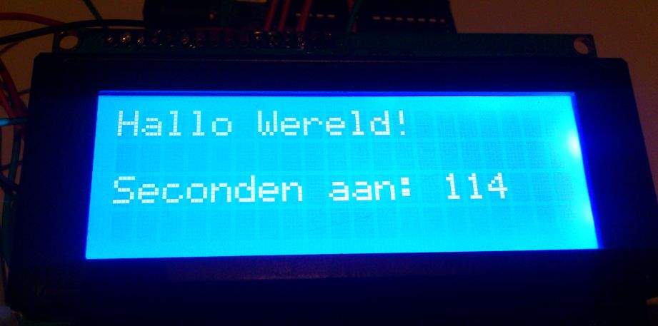
Resultaat:
Arduino via I2C module
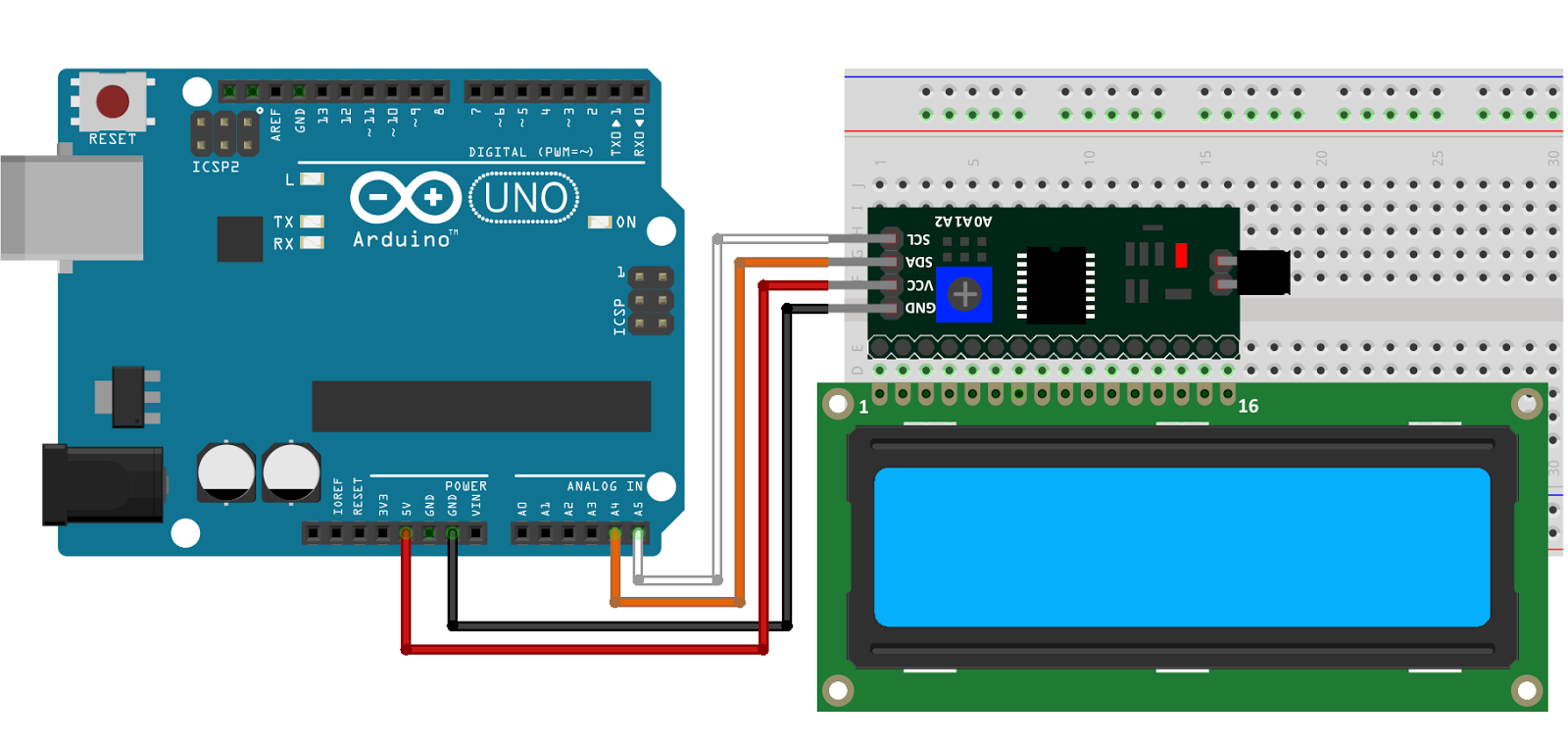
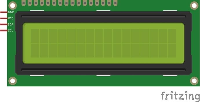
Sluit de module aan zoals aangegeven op onderstaand schema:
| I2C display module: | Arduino Pin: |
|---|---|
| GND | GND |
| +5v | +5v |
| SCA (serial data) | A4 |
| SCL (serial clock) | A5 |
Script I2C aansturing
Nieuwe script met library v1.1.2
|
1 2 3 4 5 6 7 8 9 10 11 12 13 14 15 16 17 18 19 20 21 |
//YWROBOT //Compatible with the Arduino IDE 1.0 //Library version:1.1 #include <Wire.h> #include <LiquidCrystal_I2C.h> // Display object aanmaken, eventueel i2c adres aanpassen! LiquidCrystal_I2C lcd(0x27,16,2); // set the LCD address to 0x27 for a 16 chars and 2 line display void setup() { lcd.init(); // initialiseer display lcd.backlight(); // zet verlichting aan lcd.setCursor(2,0); //positie 3, regel 1 lcd.print("Hallo"); lcd.setCursor(4,1); //positie 5, regel 2 lcd.print("Wereld!"); } void loop() { delay(1000); } |
Het script voor “Hallo wereld” icm met de “LiquidCrystal Library I2C” (oude library!)
|
1 2 3 4 5 6 7 8 9 10 11 12 13 14 15 16 17 18 19 20 21 |
// Bibliotheken inporteren #include <Wire.h> #include <LiquidCrystal_I2C.h> // Display object aanmaken, eventueel i2c adres aanpassen! LiquidCrystal_I2C lcd(0x27,2,1,0,4,5,6,7,3, POSITIVE); //SCA (serial data) A4 //SCL (serial clock) A5 void setup() { lcd.begin (16,2); // initialiseer de LCD op 16 karakters en 2 regels. } void loop() { lcd.setCursor(2,0); //positie 3, regel 1 lcd.print("Hallo"); lcd.setCursor(4,1); //positie 5, regel 2 lcd.print("Wereld!"); delay(1000); } |
Script met timer welke het aantal seconden aangeeft dat het display gebruikt wordt (oude library!)
|
1 2 3 4 5 6 7 8 9 10 11 12 13 14 15 16 17 18 19 20 |
// Bibliotheken inporteren #include <Wire.h> #include <LiquidCrystal_I2C.h> // Display object aanmaken, eventueel i2c adres aanpassen! LiquidCrystal_I2C lcd(0x27,2,1,0,4,5,6,7,3, POSITIVE); //SCA (serial data) A4 //SCL (serial clock) A5 void setup() { lcd.begin (16,2); // initialiseer de LCD op 16 karakters en 2 regels. lcd.print("Hallo Wereld!"); // Print a message to the LCD. } void loop() { lcd.setCursor(0, 1); // ga naar rij 2 kolom 0 lcd.print("Sec. aan: "); lcd.print(millis()/1000); } |
Arduino Library
Installatie van Arduino IDE libraries: Arduino info
Deze bibliotheek geeft ondersteuning voor LCD displays (1602 / 2004) met I2C ondersteuning.
- NewliquidCrystal_1.3.4.7z 4,48 MB
- NewliquidCrystal_1.3.3.7z 4,47 MB
- NewliquidCrystal_1.3.2.7z 4,47 MB
- NewliquidCrystal_1.3.1.7z 4,46 MB
- LiquidCrystal_v1.2.1.7z 163,07 kb
- LiquidCrystal_v1.2.0.7z 234,28 kb
- LiquidCrystal_v1.1.7.1.7z 232,21 kb
- LiquidCrystal-I2C (github, gedownload op 2016-01-12).7z 5,07 kb
Raspberry Pi
Aansluiten LCD 1602 op de Raspberry Pi
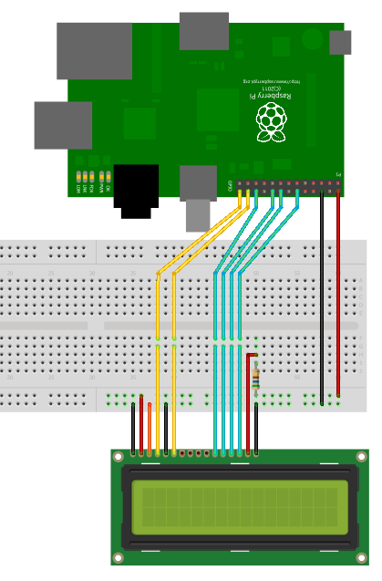
Sluit het display aan zoals aangegeven op onderstaand schema:
| Pin (van links naar rechts met het display naar boven gericht!) | Afkorting: | Omschrijving: | Raspberry functie: | Raspberry pin: |
|---|---|---|---|---|
| 1 | VSS | Ground for logic | GND | P1-06 |
| 2 | VDD | +5v power supply for logic | +5v | P1-02 |
| 3 | V0 | Power supply for LCD drive (potmeter) | Regelbare potmeter! | P1-06 |
| 4 | RS | Register selection | GPIO7 | P1-26 |
| 5 | R/W | Ground (to enable write to display) | GND | P1-06 |
| 6 | E | Enable signal for LCM | GPIO8 | P1-24 |
| 11 | DB4 | Data Bus line | GPIO25 | P1-22 |
| 12 | DB5 | Data Bus line | GPIO24 | P1-18 |
| 13 | DB6 | Data Bus line | GPIO23 | P1-16 |
| 14 | DB7 | Data Bus line | GPIO18 | P1-12 |
| 15 | A | +5v for Backlight | +5v via 560 Ohm | P1-02 |
| 16 | K | Ground for Backlight | GND | P1-06 |
Ter info:
– De RW pin zorgt ervoor dat je kan schrijven of lezen van het display, aangezien de Raspberry Pi GPIO pinnen maar 3.3v aankunnen en je alleen data stuurt naar het display is het van (groot) beland dat je deze pin op GND aansluit (alleen schrijven naar display), zodat je de Raspberry Pi niet kan beschadigen!
– Het contrast moet afgeregeld worden met een potmeter potmeter aansluiten op GND en +5V, middelste pin op pin 3 van het display.
– Niet alle displays ondersteunen direct 5v op de achtergrondverlichting, daarom is een weerstand altijd aan te raden.
Script icm RPi.GPIO bibliotheek
Het display is aan te sturen met Python en maakt gebruik van de RPi.GPIO bibliotheek, deze wordt standaard met Raspbian geïnstalleerd.
Ps. je kan de GPIO pinnen nog veranderen in de instellingen van de code, indien jet het display anders wilt aansluiten.
|
1 2 3 4 5 6 7 8 9 10 11 12 13 14 15 16 17 18 19 20 21 22 23 24 25 26 27 28 29 30 31 32 33 34 35 36 37 38 39 40 41 42 43 44 45 46 47 48 49 50 51 52 53 54 55 56 57 58 59 60 61 62 63 64 65 66 67 68 69 70 71 72 73 74 75 76 77 78 79 80 81 82 83 84 85 86 87 88 89 90 91 92 93 94 95 96 97 98 99 100 101 102 103 104 105 106 107 108 109 110 111 112 113 114 115 116 117 118 119 120 121 122 123 124 125 126 127 128 129 130 131 132 |
#import import RPi.GPIO as GPIO import time # Define GPIO to LCD mapping LCD_RS = 7 LCD_E = 8 LCD_D4 = 25 LCD_D5 = 24 LCD_D6 = 23 LCD_D7 = 18 # Define some device constants LCD_WIDTH = 16 # Maximum characters per line LCD_CHR = True LCD_CMD = False LCD_LINE_1 = 0x80 # LCD RAM address for the 1st line LCD_LINE_2 = 0xC0 # LCD RAM address for the 2nd line # Timing constants E_PULSE = 0.0005 E_DELAY = 0.0005 def main(): # Main program block GPIO.setwarnings(False) GPIO.setmode(GPIO.BCM) # Use BCM GPIO numbers GPIO.setup(LCD_E, GPIO.OUT) # E GPIO.setup(LCD_RS, GPIO.OUT) # RS GPIO.setup(LCD_D4, GPIO.OUT) # DB4 GPIO.setup(LCD_D5, GPIO.OUT) # DB5 GPIO.setup(LCD_D6, GPIO.OUT) # DB6 GPIO.setup(LCD_D7, GPIO.OUT) # DB7 # Initialise display lcd_init() while True: # Send some test lcd_string("Rasbperry Pi",LCD_LINE_1) lcd_string("DISPLAY 1602",LCD_LINE_2) time.sleep(3) # 3 second delay # Send some text lcd_string("Hallo",LCD_LINE_1) lcd_string(" Wereld!",LCD_LINE_2) time.sleep(3) # 3 second delay def lcd_init(): # Initialise display lcd_byte(0x33,LCD_CMD) # 110011 Initialise lcd_byte(0x32,LCD_CMD) # 110010 Initialise lcd_byte(0x06,LCD_CMD) # 000110 Cursor move direction lcd_byte(0x0C,LCD_CMD) # 001100 Display On,Cursor Off, Blink Off lcd_byte(0x28,LCD_CMD) # 101000 Data length, number of lines, font size lcd_byte(0x01,LCD_CMD) # 000001 Clear display time.sleep(E_DELAY) def lcd_byte(bits, mode): # Send byte to data pins # bits = data # mode = True for character # False for command GPIO.output(LCD_RS, mode) # RS # High bits GPIO.output(LCD_D4, False) GPIO.output(LCD_D5, False) GPIO.output(LCD_D6, False) GPIO.output(LCD_D7, False) if bits&0x10==0x10: GPIO.output(LCD_D4, True) if bits&0x20==0x20: GPIO.output(LCD_D5, True) if bits&0x40==0x40: GPIO.output(LCD_D6, True) if bits&0x80==0x80: GPIO.output(LCD_D7, True) # Toggle 'Enable' pin lcd_toggle_enable() # Low bits GPIO.output(LCD_D4, False) GPIO.output(LCD_D5, False) GPIO.output(LCD_D6, False) GPIO.output(LCD_D7, False) if bits&0x01==0x01: GPIO.output(LCD_D4, True) if bits&0x02==0x02: GPIO.output(LCD_D5, True) if bits&0x04==0x04: GPIO.output(LCD_D6, True) if bits&0x08==0x08: GPIO.output(LCD_D7, True) # Toggle 'Enable' pin lcd_toggle_enable() def lcd_toggle_enable(): # Toggle enable time.sleep(E_DELAY) GPIO.output(LCD_E, True) time.sleep(E_PULSE) GPIO.output(LCD_E, False) time.sleep(E_DELAY) def lcd_string(message,line): # Send string to display message = message.ljust(LCD_WIDTH," ") lcd_byte(line, LCD_CMD) for i in range(LCD_WIDTH): lcd_byte(ord(message[i]),LCD_CHR) if __name__ == '__main__': try: main() except KeyboardInterrupt: pass finally: lcd_byte(0x01, LCD_CMD) lcd_string("Tot ziens!",LCD_LINE_1) GPIO.cleanup() |
Start het script met: python lcd1602.py
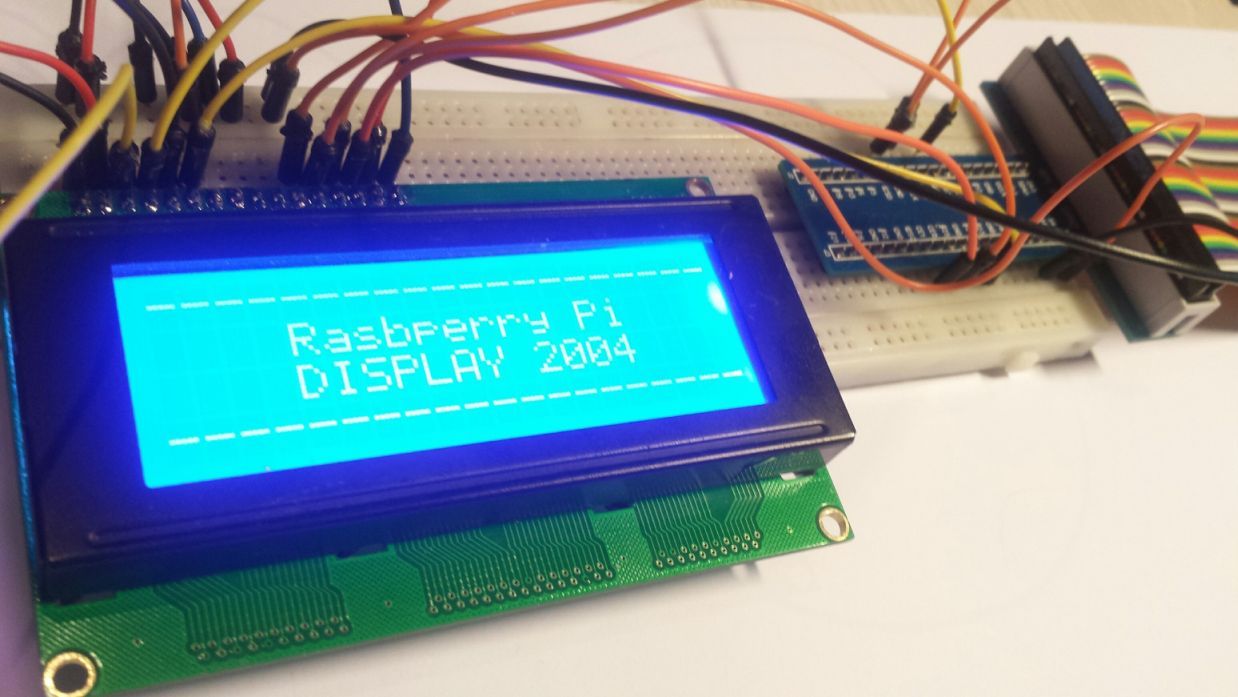
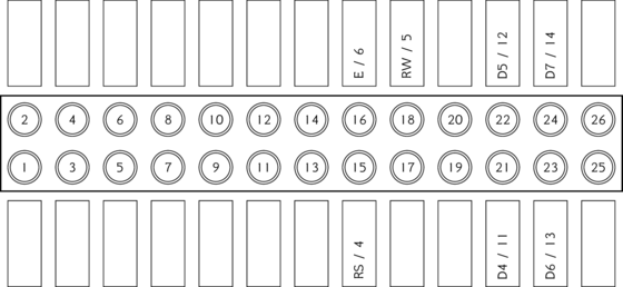
Aansluiten LCD 2004 op de Raspberry Pi
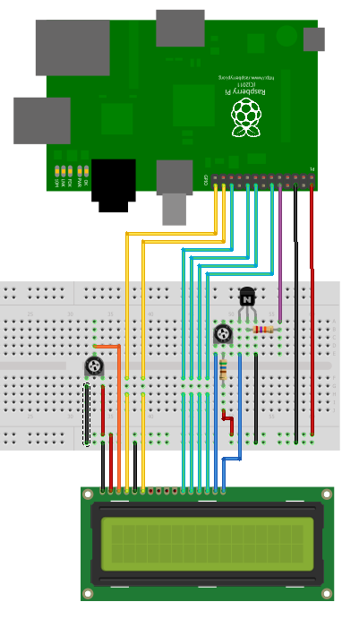
Sluit het display aan zoals aangegeven op onderstaand schema:
Ter info:
– De RW pin zorgt ervoor dat je kan schrijven of lezen van het display, aangezien de Raspberry Pi GPIO pinnen maar 3.3v aankunnen en je alleen data stuurt naar het display is het van (groot) beland dat je deze pin op GND aansluit (alleen schrijven naar display), zodat je de Raspberry Pi niet kan beschadigen!
– Het contrast moet afgeregeld worden met een potmeter potmeter aansluiten op GND en +5V, middelste pin op pin 3 van het display.
– Niet alle displays ondersteunen direct 5v op de achtergrondverlichting, daarom is een weerstand altijd aan te raden.
Script icm RPi.GPIO bibliotheek
Het display is aan te sturen met Python en maakt gebruik van de RPi.GPIO bibliotheek, deze wordt standaard met Raspbian geïnstalleerd.
Ps. je kan de GPIO pinnen nog veranderen in de instellingen van de code, indien jet het display anders wilt aansluiten.
|
1 2 3 4 5 6 7 8 9 10 11 12 13 14 15 16 17 18 19 20 21 22 23 24 25 26 27 28 29 30 31 32 33 34 35 36 37 38 39 40 41 42 43 44 45 46 47 48 49 50 51 52 53 54 55 56 57 58 59 60 61 62 63 64 65 66 67 68 69 70 71 72 73 74 75 76 77 78 79 80 81 82 83 84 85 86 87 88 89 90 91 92 93 94 95 96 97 98 99 100 101 102 103 104 105 106 107 108 109 110 111 112 113 114 115 116 117 118 119 120 121 122 123 124 125 126 127 128 129 130 131 132 133 134 135 136 137 138 139 140 141 142 143 144 145 146 147 148 149 150 151 152 153 154 155 156 157 158 159 |
#import import RPi.GPIO as GPIO import time # Define GPIO to LCD mapping LCD_RS = 7 LCD_E = 8 LCD_D4 = 25 LCD_D5 = 24 LCD_D6 = 23 LCD_D7 = 18 LED_ON = 15 # Define some device constants LCD_WIDTH = 20 # Maximum characters per line LCD_CHR = True LCD_CMD = False LCD_LINE_1 = 0x80 # LCD RAM address for the 1st line LCD_LINE_2 = 0xC0 # LCD RAM address for the 2nd line LCD_LINE_3 = 0x94 # LCD RAM address for the 3rd line LCD_LINE_4 = 0xD4 # LCD RAM address for the 4th line # Timing constants E_PULSE = 0.0005 E_DELAY = 0.0005 def main(): # Main program block GPIO.setmode(GPIO.BCM) # Use BCM GPIO numbers GPIO.setup(LCD_E, GPIO.OUT) # E GPIO.setup(LCD_RS, GPIO.OUT) # RS GPIO.setup(LCD_D4, GPIO.OUT) # DB4 GPIO.setup(LCD_D5, GPIO.OUT) # DB5 GPIO.setup(LCD_D6, GPIO.OUT) # DB6 GPIO.setup(LCD_D7, GPIO.OUT) # DB7 GPIO.setup(LED_ON, GPIO.OUT) # Backlight enable # Initialise display lcd_init() # Toggle backlight on-off-on lcd_backlight(True) time.sleep(0.5) lcd_backlight(False) time.sleep(0.5) lcd_backlight(True) time.sleep(0.5) while True: # Send some centred test lcd_string("--------------------",LCD_LINE_1,2) lcd_string("Rasbperry Pi",LCD_LINE_2,2) lcd_string("DISPLAY 2004",LCD_LINE_3,2) lcd_string("--------------------",LCD_LINE_4,2) time.sleep(3) # 3 second delay lcd_string("Hallo",LCD_LINE_1,1) lcd_string(" Wereld!",LCD_LINE_2,1) lcd_string("",LCD_LINE_3,2) lcd_string("20x4 LCD Module Test",LCD_LINE_4,2) time.sleep(3) # 3 second delay def lcd_init(): # Initialise display lcd_byte(0x33,LCD_CMD) # 110011 Initialise lcd_byte(0x32,LCD_CMD) # 110010 Initialise lcd_byte(0x06,LCD_CMD) # 000110 Cursor move direction lcd_byte(0x0C,LCD_CMD) # 001100 Display On,Cursor Off, Blink Off lcd_byte(0x28,LCD_CMD) # 101000 Data length, number of lines, font size lcd_byte(0x01,LCD_CMD) # 000001 Clear display time.sleep(E_DELAY) def lcd_byte(bits, mode): # Send byte to data pins # bits = data # mode = True for character # False for command GPIO.output(LCD_RS, mode) # RS # High bits GPIO.output(LCD_D4, False) GPIO.output(LCD_D5, False) GPIO.output(LCD_D6, False) GPIO.output(LCD_D7, False) if bits&0x10==0x10: GPIO.output(LCD_D4, True) if bits&0x20==0x20: GPIO.output(LCD_D5, True) if bits&0x40==0x40: GPIO.output(LCD_D6, True) if bits&0x80==0x80: GPIO.output(LCD_D7, True) # Toggle 'Enable' pin lcd_toggle_enable() # Low bits GPIO.output(LCD_D4, False) GPIO.output(LCD_D5, False) GPIO.output(LCD_D6, False) GPIO.output(LCD_D7, False) if bits&0x01==0x01: GPIO.output(LCD_D4, True) if bits&0x02==0x02: GPIO.output(LCD_D5, True) if bits&0x04==0x04: GPIO.output(LCD_D6, True) if bits&0x08==0x08: GPIO.output(LCD_D7, True) # Toggle 'Enable' pin lcd_toggle_enable() def lcd_toggle_enable(): # Toggle enable time.sleep(E_DELAY) GPIO.output(LCD_E, True) time.sleep(E_PULSE) GPIO.output(LCD_E, False) time.sleep(E_DELAY) def lcd_string(message,line,style): # Send string to display # style=1 Left justified # style=2 Centred # style=3 Right justified if style==1: message = message.ljust(LCD_WIDTH," ") elif style==2: message = message.center(LCD_WIDTH," ") elif style==3: message = message.rjust(LCD_WIDTH," ") lcd_byte(line, LCD_CMD) for i in range(LCD_WIDTH): lcd_byte(ord(message[i]),LCD_CHR) def lcd_backlight(flag): # Toggle backlight on-off-on GPIO.output(LED_ON, flag) if __name__ == '__main__': try: main() except KeyboardInterrupt: pass finally: lcd_byte(0x01, LCD_CMD) lcd_string("Tot ziens!",LCD_LINE_1,2) GPIO.cleanup() |
Start het script met: python lcd2004.py
Resultaat:
Python Library gebruiken
Wat heb je nodig?
1) Python Hitachi HD44780 bibliotheek
Sluit het display aan zoals aangegeven op onderstaand schema:
Voorbeeld script icm met de Python HD44780 bibliotheek
|
1 2 3 4 5 6 7 8 9 10 11 12 13 14 15 16 17 18 19 20 21 22 23 24 25 26 27 28 29 30 31 32 33 34 35 36 37 38 39 40 41 42 43 44 45 46 47 48 49 50 51 52 53 54 55 56 57 58 59 60 61 62 63 64 65 66 67 68 69 70 71 72 73 74 75 76 77 78 79 80 81 82 83 84 85 86 87 88 89 90 91 92 93 94 95 96 97 98 99 100 101 102 103 104 105 106 107 108 109 110 111 112 113 114 115 116 117 118 119 120 121 122 123 124 125 126 127 128 129 130 131 |
#!/usr/bin/env python # -*- coding: utf-8 -*- from __future__ import print_function, division, absolute_import, unicode_literals import sys from RPLCD import CharLCD from RPLCD import Alignment, CursorMode, ShiftMode from RPLCD import cursor, cleared try: input = raw_input except NameError: pass try: unichr = unichr except NameError: unichr = chr lcd = CharLCD() input('Display should be blank. ') lcd.cursor_mode = CursorMode.blink input('The cursor should now blink. ') lcd.cursor_mode = CursorMode.line input('The cursor should now be a line. ') lcd.write_string('Hello world!') input('"Hello world!" should be on the LCD. ') assert lcd.cursor_pos == (0, 12), 'cursor_pos should now be (0, 12)' lcd.cursor_pos = (1, 0) lcd.write_string('2') lcd.cursor_pos = (2, 0) lcd.write_string('3') lcd.cursor_pos = (3, 0) lcd.write_string('4') assert lcd.cursor_pos == (3, 1), 'cursor_pos should now be (3, 1)' input('Lines 2, 3 and 4 should now be labelled with the right numbers. ') lcd.clear() input('Display should now be clear, cursor should be at initial position. ') lcd.cursor_pos = (0, 5) lcd.write_string('12345') input('The string should have a left offset of 5 characters. ') lcd.write_shift_mode = ShiftMode.display lcd.cursor_pos = (1, 5) lcd.write_string('12345') input('Both strings should now be at column 0. ') lcd.write_shift_mode = ShiftMode.cursor lcd.cursor_pos = (2, 5) lcd.write_string(lcd.write_shift_mode.name) input('The string "cursor" should now be on the third row, column 0. ') lcd.home() input('Cursor should now be at initial position. Everything should be shifted to the right by 5 characters. ') with cursor(lcd, 3, 19): lcd.write_string('X') input('The last character on the LCD should now be an "X"') lcd.display_enabled = False input('Display should now be blank. ') with cleared(lcd): lcd.write_string('Eggs, Ham, Bacon\n\rand Spam') lcd.display_enabled = True input('Display should now show "Eggs, Ham, Bacon and Spam". ') lcd.shift_display(4) input('Text should now be shifted to the right by 4 characters. ') lcd.shift_display(-4) input('Shift should now be undone. ') lcd.text_align_mode = Alignment.right lcd.write_string(' Spam') input('The word "Spam" should now be inverted. ') lcd.text_align_mode = Alignment.left lcd.write_string(' Wurscht') input('The word "mapS" should now be replaced with "Wurscht". ') lcd.clear() lcd.write_string('1\n') lcd.write_string('2\n') lcd.write_string('3\n') lcd.write_string('4') input('The numbers 1-4 should now be displayed, each line shifted to the right by 1 char more than the previous. ') lcd.clear() lcd.write_string('This is a long string that will wrap across multiple lines!') input('Text should nicely wrap around lines. ') lcd.clear() lcd.cursor_mode = CursorMode.hide lcd.write_string('Paris: 21{deg}C\n\rZ{uuml}rich: 18{deg}C'.format(deg=unichr(176), uuml=unichr(129))) print('Text should now show "Paris: 21°C, Zürich: 18°C" without any encoding issues.', end='') input() # Test custom chars lcd.clear() happy = (0b00000, 0b01010, 0b01010, 0b00000, 0b10001, 0b10001, 0b01110, 0b00000) sad = (0b00000, 0b01010, 0b01010, 0b00000, 0b01110, 0b10001, 0b10001, 0b00000) lcd.create_char(0, sad) lcd.write_string(unichr(0)) lcd.create_char(1, happy) lcd.write_string(unichr(1)) input('You should now see a sad and a happy face next to each other. ') lcd.create_char(0, happy) lcd.home() lcd.write_string(unichr(0)) input('Now both faces should be happy. ') lcd.clear() lcd.write_string('12345678901234567890\r\n2nd line') input('The first line should be filled with numbers, the second line should show "2nd line"') lcd.clear() lcd.write_string('999456..............\n\r\n\n\n123') input('The display should show "123456...................." on the first line') lcd.clear() print('Test done.') |
Bronnen:
www.raspberrypi-spy.co.uk #1
www.raspberrypi-spy.co.uk #2
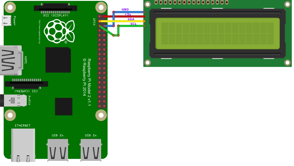
Raspberry Pi via I2C module
Sluit de module aan zoals aangegeven op onderstaand schema:
| Raspberry Pi pin: | I2C module pin: |
|---|---|
| +5v | +5v |
| GND | GND |
| 3 (GPIO2) SDA | SDA |
| 5 (GPIO3) SCL | SCL |
Ps. Altijd de pinout van je Raspberry Pi controleren, deze kan verschillen per versie.
Wat heb je nodig?
1) I2C bus gebruiken op de Raspberry Pi
Om de I2C bus in Python te gebruiken moet je een module installeren, genaamd SMBUS, dit kan via APT-GET met het commando: sudo apt-get install python-smbus
|
1 2 3 4 5 6 7 8 9 10 11 12 13 14 |
Reading package lists... Done Building dependency tree Reading state information... Done The following NEW packages will be installed: python-smbus 0 upgraded, 1 newly installed, 0 to remove and 79 not upgraded. Need to get 11.9 kB of archives. After this operation, 95.2 kB of additional disk space will be used. Get:1 http://archive.raspberrypi.org/debian/ wheezy/main python-smbus armhf 3.1.1+svn-1 [11.9 kB] Fetched 11.9 kB in 0s (131 kB/s) Selecting previously unselected package python-smbus. (Reading database ... 78301 files and directories currently installed.) Unpacking python-smbus (from .../python-smbus_3.1.1+svn-1_armhf.deb) ... Setting up python-smbus (3.1.1+svn-1) ... |
Je kan dan de module importeren in python door middel van: import smbus
Python script module #1 (2015) (werkt beter met 2004 displays)
Er is een script (module) gemaakt om eenvoudig met het display te kunnen communiceren via de I2C bus, het bestand I2C_LCD_driver.py:
|
1 2 3 4 5 6 7 8 9 10 11 12 13 14 15 16 17 18 19 20 21 22 23 24 25 26 27 28 29 30 31 32 33 34 35 36 37 38 39 40 41 42 43 44 45 46 47 48 49 50 51 52 53 54 55 56 57 58 59 60 61 62 63 64 65 66 67 68 69 70 71 72 73 74 75 76 77 78 79 80 81 82 83 84 85 86 87 88 89 90 91 92 93 94 95 96 97 98 99 100 101 102 103 104 105 106 107 108 109 110 111 112 113 114 115 116 117 118 119 120 121 122 123 124 125 126 127 128 129 130 131 132 133 134 135 136 137 138 139 140 141 142 143 144 145 146 147 148 149 150 151 152 153 154 155 156 157 158 159 160 161 162 163 164 165 166 167 168 169 170 171 172 173 174 175 176 |
# -*- coding: utf-8 -*- # Original code found at: # https://gist.github.com/DenisFromHR/cc863375a6e19dce359d """ Compiled, mashed and generally mutilated 2014-2015 by Denis Pleic Made available under GNU GENERAL PUBLIC LICENSE # Modified Python I2C library for Raspberry Pi # as found on http://www.recantha.co.uk/blog/?p=4849 # Joined existing 'i2c_lib.py' and 'lcddriver.py' into a single library # added bits and pieces from various sources # By DenisFromHR (Denis Pleic) # 2015-02-10, ver 0.1 """ # i2c bus (0 -- original Pi, 1 -- Rev 2 Pi) I2CBUS = 0 # LCD Address ADDRESS = 0x27 import smbus from time import sleep class i2c_device: def __init__(self, addr, port=I2CBUS): self.addr = addr self.bus = smbus.SMBus(port) # Write a single command def write_cmd(self, cmd): self.bus.write_byte(self.addr, cmd) sleep(0.0001) # Write a command and argument def write_cmd_arg(self, cmd, data): self.bus.write_byte_data(self.addr, cmd, data) sleep(0.0001) # Write a block of data def write_block_data(self, cmd, data): self.bus.write_block_data(self.addr, cmd, data) sleep(0.0001) # Read a single byte def read(self): return self.bus.read_byte(self.addr) # Read def read_data(self, cmd): return self.bus.read_byte_data(self.addr, cmd) # Read a block of data def read_block_data(self, cmd): return self.bus.read_block_data(self.addr, cmd) # commands LCD_CLEARDISPLAY = 0x01 LCD_RETURNHOME = 0x02 LCD_ENTRYMODESET = 0x04 LCD_DISPLAYCONTROL = 0x08 LCD_CURSORSHIFT = 0x10 LCD_FUNCTIONSET = 0x20 LCD_SETCGRAMADDR = 0x40 LCD_SETDDRAMADDR = 0x80 # flags for display entry mode LCD_ENTRYRIGHT = 0x00 LCD_ENTRYLEFT = 0x02 LCD_ENTRYSHIFTINCREMENT = 0x01 LCD_ENTRYSHIFTDECREMENT = 0x00 # flags for display on/off control LCD_DISPLAYON = 0x04 LCD_DISPLAYOFF = 0x00 LCD_CURSORON = 0x02 LCD_CURSOROFF = 0x00 LCD_BLINKON = 0x01 LCD_BLINKOFF = 0x00 # flags for display/cursor shift LCD_DISPLAYMOVE = 0x08 LCD_CURSORMOVE = 0x00 LCD_MOVERIGHT = 0x04 LCD_MOVELEFT = 0x00 # flags for function set LCD_8BITMODE = 0x10 LCD_4BITMODE = 0x00 LCD_2LINE = 0x08 LCD_1LINE = 0x00 LCD_5x10DOTS = 0x04 LCD_5x8DOTS = 0x00 # flags for backlight control LCD_BACKLIGHT = 0x08 LCD_NOBACKLIGHT = 0x00 En = 0b00000100 # Enable bit Rw = 0b00000010 # Read/Write bit Rs = 0b00000001 # Register select bit class lcd: #initializes objects and lcd def __init__(self): self.lcd_device = i2c_device(ADDRESS) self.lcd_write(0x03) self.lcd_write(0x03) self.lcd_write(0x03) self.lcd_write(0x02) self.lcd_write(LCD_FUNCTIONSET | LCD_2LINE | LCD_5x8DOTS | LCD_4BITMODE) self.lcd_write(LCD_DISPLAYCONTROL | LCD_DISPLAYON) #self.lcd_write(LCD_CLEARDISPLAY) #Reset display standaard uit, zo wordt hij mooi ge-updated! self.lcd_write(LCD_ENTRYMODESET | LCD_ENTRYLEFT) sleep(0.2) # clocks EN to latch command def lcd_strobe(self, data): self.lcd_device.write_cmd(data | En | LCD_BACKLIGHT) sleep(.0005) self.lcd_device.write_cmd(((data & ~En) | LCD_BACKLIGHT)) sleep(.0001) def lcd_write_four_bits(self, data): self.lcd_device.write_cmd(data | LCD_BACKLIGHT) self.lcd_strobe(data) # write a command to lcd def lcd_write(self, cmd, mode=0): self.lcd_write_four_bits(mode | (cmd & 0xF0)) self.lcd_write_four_bits(mode | ((cmd << 4) & 0xF0)) # write a character to lcd (or character rom) 0x09: backlight | RS=DR< # works! def lcd_write_char(self, charvalue, mode=1): self.lcd_write_four_bits(mode | (charvalue & 0xF0)) self.lcd_write_four_bits(mode | ((charvalue << 4) & 0xF0)) # put string function with optional char positioning def lcd_display_string(self, string, line=1, pos=0): if line == 1: pos_new = pos elif line == 2: pos_new = 0x40 + pos elif line == 3: pos_new = 0x14 + pos elif line == 4: pos_new = 0x54 + pos self.lcd_write(0x80 + pos_new) for char in string: self.lcd_write(ord(char), Rs) # clear lcd and set to home def lcd_clear(self): self.lcd_write(LCD_CLEARDISPLAY) self.lcd_write(LCD_RETURNHOME) # define backlight on/off (lcd.backlight(1); off= lcd.backlight(0) def backlight(self, state): # for state, 1 = on, 0 = off if state == 1: self.lcd_device.write_cmd(LCD_BACKLIGHT) elif state == 0: self.lcd_device.write_cmd(LCD_NOBACKLIGHT) # add custom characters (0 - 7) def lcd_load_custom_chars(self, fontdata): self.lcd_write(0x40); for char in fontdata: for line in char: self.lcd_write_char(line) |
Vul hierboven in het bestand het juiste i2c adres in:
ADDRESS = 0x27
Script
Het script lcd.py om regels naar het display te schrijven:
|
1 2 3 4 5 6 |
import I2C_LCD_driver mylcd = I2C_LCD_driver.lcd() mylcd.lcd_display_string("Hallo", 1) #Rij 1 mylcd.lcd_display_string("Wereld!", 2, 2) #Rij 2, Kolom 3 (start bij 0) mylcd.backlight(1) # Backlight aan. |
Start het script met: python lcd.py
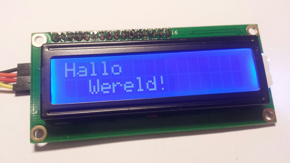
Resultaat:
Python script module #2 (verouderd)
Er is een script (module) gemaakt om eenvoudig met het display te kunnen communiceren via de I2C bus, het bestand pylcdlib.py:
|
1 2 3 4 5 6 7 8 9 10 11 12 13 14 15 16 17 18 19 20 21 22 23 24 25 26 27 28 29 30 31 32 33 34 35 36 37 38 39 40 41 42 43 44 45 46 47 48 49 50 51 52 53 54 55 56 57 58 59 60 61 62 63 64 65 66 67 68 69 70 71 72 73 74 75 76 77 78 79 80 81 82 83 84 85 86 87 88 89 90 91 92 93 94 95 96 97 98 99 100 101 102 103 104 105 106 107 108 109 |
import smbus from time import * # General i2c device class so that other devices can be added easily class i2c_device: def __init__(self, addr, port): self.addr = addr self.bus = smbus.SMBus(port) def write(self, byte): self.bus.write_byte(self.addr, byte) def read(self): return self.bus.read_byte(self.addr) def read_nbytes_data(self, data, n): # For sequential reads > 1 byte return self.bus.read_i2c_block_data(self.addr, data, n) class lcd: #initializes objects and lcd ''' Port definitions addr, en,rw,rs,d4,d5,d6,d7,bl 0x27, 2, 1, 0, 4, 5, 6, 7, 3 ''' def __init__(self, addr, port): self.lcd_device = i2c_device(addr, port) self.backlight=1; #default backlight on #set 4 bit mode self.lcd_device_writebl(0x20) self.lcd_strobe() sleep(0.0005) self.lcd_strobe() sleep(0.0005) self.lcd_strobe() sleep(0.0005) self.lcd_write(0x28) self.lcd_write(0x08) self.lcd_write(0x01) self.lcd_write(0x06) self.lcd_write(0x0C) self.lcd_write(0x0F) #wrapper to self.lcd_device.write fir backlight control def lcd_device_writebl(self,value): if self.backlight: self.lcd_device.write(value | 0x08); else: self.lcd_device.write(value) # control backlight on=1 or off=0 def lcd_backlight(self,on): self.backlight=on self.lcd_strobe() # clocks EN to latch command def lcd_strobe(self): #bit 2 self.lcd_device_writebl((self.lcd_device.read() | 0x04)) self.lcd_device_writebl((self.lcd_device.read() & 0xFB)) # write a command to lcd def lcd_write(self, cmd): self.lcd_device_writebl((cmd >> 4)<<4) self.lcd_strobe() self.lcd_device_writebl((cmd & 0x0F)<<4) self.lcd_strobe() self.lcd_device_writebl(0x0) # write a character to lcd (or character rom) def lcd_write_char(self, charvalue): self.lcd_device_writebl((0x01 | (charvalue >> 4)<<4)) self.lcd_strobe() self.lcd_device_writebl((0x01 | (charvalue & 0x0F)<<4)) self.lcd_strobe() self.lcd_device_writebl(0x0) # put char function def lcd_putc(self, char): self.lcd_write_char(ord(char)) # put string function def lcd_puts(self, string, line): if line == 1: self.lcd_write(0x80) if line == 2: self.lcd_write(0xC0) if line == 3: self.lcd_write(0x94) if line == 4: self.lcd_write(0xD4) for char in string: self.lcd_putc(char) # clear lcd and set to home def lcd_clear(self): self.lcd_write(0x1) self.lcd_write(0x2) # add custom characters (0 - 7) def lcd_load_custon_chars(self, fontdata): self.lcd_device.bus.write(0x40); for char in fontdata: for line in char: self.lcd_write_char(line) |
Script
Het script lcd.py om regels naar het display te schrijven:
|
1 2 3 4 5 6 7 8 |
import pylcdlib lcd = pylcdlib.lcd(0x27,1) #I2C apparaat op adres 0x27. lcd.lcd_write(0x0C) #Cursor uitschakelen. lcd.lcd_write(0x01) #Scherm leegmaken. lcd.lcd_puts("Hallo", 1) #Tekst voor LCD display lijn 1. lcd.lcd_puts(" Wereld!", 2) #Tekst voor LCD display lijn 2. lcd.lcd_backlight(1) #Achterverlichting aanzetten. |
Start het script met: python lcd.py
I2C adres:
Meestal is het adres 0x27, mocht dit anders zijn dan kun je vanuit de Raspberry Pi dit commando uitvoeren om te kijken welk I2C adressen er zijn gevonden: sudo i2cdetect -y 1
|
1 2 3 4 5 6 7 8 9 |
0 1 2 3 4 5 6 7 8 9 a b c d e f 00: -- -- -- -- -- -- -- -- -- -- -- -- -- 10: -- -- -- -- -- -- -- -- -- -- -- -- -- -- -- -- 20: -- -- -- -- -- -- -- 27 -- -- -- -- -- -- -- -- 30: -- -- -- -- -- -- -- -- -- -- -- -- -- -- -- -- 40: -- -- -- -- -- -- -- -- -- -- -- -- -- -- -- -- 50: -- -- -- -- -- -- -- -- -- -- -- -- -- -- -- -- 60: -- -- -- -- -- -- -- -- -- -- -- -- -- -- -- -- 70: -- -- -- -- -- -- -- -- |
Foutmelding
Krijg je deze foutmelding: IOError: [Errno 5] Input/output error, dat is de I2C bus nog niet (juist) geïnitialiseerd, je kan daarvoor het volgende trucje toepassen in python:
|
1 2 3 4 5 6 7 8 9 10 11 12 13 14 |
import pylcdlib import subprocess try: lcd = pylcdlib.lcd(0x27,1) #I2C apparaat op adres 0x27. lcd.lcd_write(0x0C) #Cursor uitschakelen. lcd.lcd_write(0x01) #Scherm leegmaken. lcd.lcd_puts("Hallo", 1) #Tekst voor LCD display lijn 1. lcd.lcd_puts(" Wereld!", 2) #Tekst voor LCD display lijn 2. lcd.lcd_backlight(1) #Achterverlichting aanzetten. except IOError: subprocess.call(['i2cdetect', '-y', '1']) #optionele vlag als signaal om de gegevens eventueel nog een #keer naar het display te sturen. flag = 1 |
Bronnen:
raspberrypi.org
stackoverflow.com
circuitbasics.com
Raspberry Pi Library
RPLCD
A Python 3/2 Raspberry PI Character LCD library for the Hitachi HD44780 controller. It supports both GPIO (parallel) mode as well as boards with an I²C port expander (e.g. the PCF8574 or the MCP23008).
This library is inspired by Adafruit Industries’ CharLCD library as well as by Arduino’s LiquidCrystal library.
For GPIO mode, no external dependencies (except the RPi.GPIO library, which comes preinstalled on Raspbian) are needed to use this library. If you want to control LCDs via I²C, then you also need the python-smbus or smbus2 library. If you want to control the LCD with pigpio, you have to install the pigpio library.
If you’re trying to get started with RPLCD, you should probably read the docs :)
Setup
You can install RPLCD directly from PyPI using pip:
|
1 |
$ sudo pip install RPLCD |
If you want to use I²C, you also need either the smbus or smbus2 library:
|
1 2 3 |
$ sudo apt install python-smbus or $ sudo pip install smbus2 |
RPLCD will first try to use smbus if available and if not, fall back to smbus2.
You can also install the library manually without pip. Either just copy the scripts to your working directory and import them, or download the repository and run python setup.py install to install it into your Python package directory.
Features
Implemented
- Simple to use API
- Support for both 4 bit and 8 bit modes
- Support for both parallel (GPIO) and I²C connection
- Support for custom characters
- Support for backlight control circuits
- Built-in support for A00, A02 (standard HD44780) or ST0B (see ST7066, page 11) character tables
- Python 2/3 compatible
- Caching: Only write characters if they changed
- No external dependencies (except RPi.GPIO, and python-smbus or smbus2 if you need I²C support)
Wishlist
These things may get implemented in the future, depending on my free time and motivation:
- MicroPython port
Supported I²C Port Expanders
- PCF8574 (used by a lot of I²C LCD adapters on Ali Express)
- MCP23008 (used in Adafruit I²C LCD backpack)
- MCP23017
Documentation
- Stable (released on PyPI): http://rplcd.readthedocs.io/en/stable/
- Latest (current master): http://rplcd.readthedocs.io/en/latest/
Installatie via GIT (github)
|
1 2 |
cd /usr/src/ sudo git clone https://github.com/dbrgn/RPLCD.git |
|
1 2 3 4 5 6 |
Cloning into 'RPLCD'... remote: Counting objects: 398, done. remote: Total 398 (delta 0), reused 0 (delta 0), pack-reused 398 Receiving objects: 100% (398/398), 197.74 KiB | 0 bytes/s, done. Resolving deltas: 100% (217/217), done. Checking connectivity... done. |
|
1 2 |
cd RPLCD sudo python setup.py install |
|
1 2 3 4 5 6 7 8 9 10 11 12 13 14 15 16 17 18 19 20 21 22 23 24 25 26 27 28 29 30 31 32 33 34 35 36 37 38 39 40 41 42 43 44 45 46 47 48 49 |
running install running bdist_egg running egg_info creating RPLCD.egg-info writing RPLCD.egg-info/PKG-INFO writing top-level names to RPLCD.egg-info/top_level.txt writing dependency_links to RPLCD.egg-info/dependency_links.txt writing manifest file 'RPLCD.egg-info/SOURCES.txt' reading manifest file 'RPLCD.egg-info/SOURCES.txt' reading manifest template 'MANIFEST.in' warning: no previously-included files matching '*.pyc' found under directory '*' writing manifest file 'RPLCD.egg-info/SOURCES.txt' installing library code to build/bdist.linux-armv7l/egg running install_lib running build_py creating build creating build/lib.linux-armv7l-2.7 creating build/lib.linux-armv7l-2.7/RPLCD copying RPLCD/lcd.py -> build/lib.linux-armv7l-2.7/RPLCD copying RPLCD/contextmanagers.py -> build/lib.linux-armv7l-2.7/RPLCD copying RPLCD/__init__.py -> build/lib.linux-armv7l-2.7/RPLCD copying RPLCD/enum.py -> build/lib.linux-armv7l-2.7/RPLCD creating build/bdist.linux-armv7l creating build/bdist.linux-armv7l/egg creating build/bdist.linux-armv7l/egg/RPLCD copying build/lib.linux-armv7l-2.7/RPLCD/lcd.py -> build/bdist.linux-armv7l/egg/RPLCD copying build/lib.linux-armv7l-2.7/RPLCD/contextmanagers.py -> build/bdist.linux-armv7l/egg/RPLCD copying build/lib.linux-armv7l-2.7/RPLCD/__init__.py -> build/bdist.linux-armv7l/egg/RPLCD copying build/lib.linux-armv7l-2.7/RPLCD/enum.py -> build/bdist.linux-armv7l/egg/RPLCD byte-compiling build/bdist.linux-armv7l/egg/RPLCD/lcd.py to lcd.pyc byte-compiling build/bdist.linux-armv7l/egg/RPLCD/contextmanagers.py to contextmanagers.pyc byte-compiling build/bdist.linux-armv7l/egg/RPLCD/__init__.py to __init__.pyc byte-compiling build/bdist.linux-armv7l/egg/RPLCD/enum.py to enum.pyc creating build/bdist.linux-armv7l/egg/EGG-INFO copying RPLCD.egg-info/PKG-INFO -> build/bdist.linux-armv7l/egg/EGG-INFO copying RPLCD.egg-info/SOURCES.txt -> build/bdist.linux-armv7l/egg/EGG-INFO copying RPLCD.egg-info/dependency_links.txt -> build/bdist.linux-armv7l/egg/EGG-INFO copying RPLCD.egg-info/top_level.txt -> build/bdist.linux-armv7l/egg/EGG-INFO zip_safe flag not set; analyzing archive contents... creating dist creating 'dist/RPLCD-0.3.0-py2.7.egg' and adding 'build/bdist.linux-armv7l/egg' to it removing 'build/bdist.linux-armv7l/egg' (and everything under it) Processing RPLCD-0.3.0-py2.7.egg Copying RPLCD-0.3.0-py2.7.egg to /usr/local/lib/python2.7/dist-packages Adding RPLCD 0.3.0 to easy-install.pth file Installed /usr/local/lib/python2.7/dist-packages/RPLCD-0.3.0-py2.7.egg Processing dependencies for RPLCD==0.3.0 Finished processing dependencies for RPLCD==0.3.0 |
Github: https://github.com/dbrgn/RPLCD
ESP8266
Code flashen:
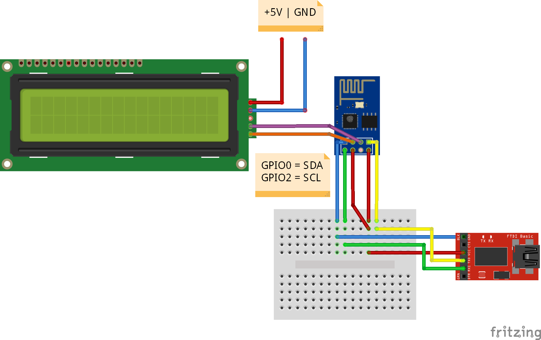
Voordat je het display kan aansluiten, verbind GPIO 0 op GND en flash de code in de ESP8266 module.
Display aansluiten:
Eenmaal de code geflashed, Sluit het LCD display aan op GPIO 0 en GPIO 2 volgens onderstaand schema:
Script voor ArduinoIDE
1) Firmware flashen met ArduinoIDE
2) Arduino LiquidCrystal I2C biblotheek
Een voorbeeld code voor een LCD 1602 via I2C:
|
1 2 3 4 5 6 7 8 9 10 11 12 13 14 15 16 17 18 19 20 21 |
#include <Wire.h> #include <LiquidCrystal_I2C.h> LiquidCrystal_I2C lcd(0x27,16,2); // Changed for LCD1602 0x27 I2C address and columns by rows. uint8_t heart[8] = {0x0,0xa,0x1f,0x1f,0xe,0x4,0x0}; // Bitmap character example void setup() { lcd.begin(); // changed instead lcd.init() method in old library version lcd.backlight(); lcd.createChar(1, heart); //store character in LCD1602 memory } void loop() { lcd.home(); lcd.print("ESP8266 with"); lcd.setCursor(10, 0); // columns, rows !! care the order. lcd.write(byte(1)); // write sprite character code at Cursor location lcd.setCursor(0, 1); lcd.print("LiquidCrystalI2C"); } |
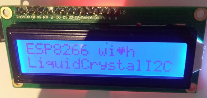
Het resultaat:
Script voor NodeMCU
Wat heb je nodig?
1) ESPlorer IDE
Upload deze “library” code als lcd1602.lua
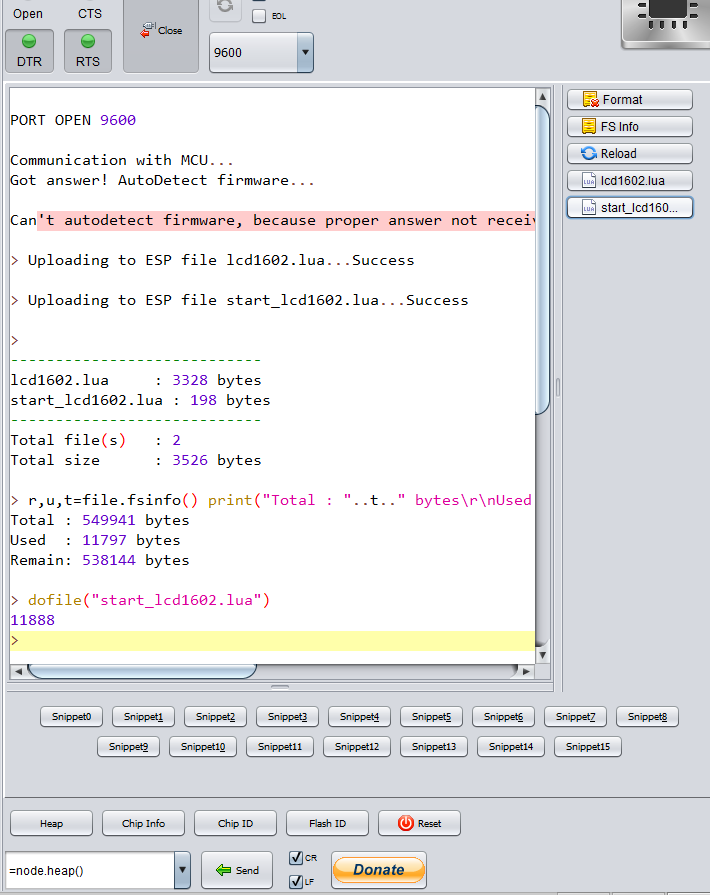
Tip: Download de code sla het op als bestand, en gebruik de “Upload…” knop in ESPlorer.
|
1 2 3 4 5 6 7 8 9 10 11 12 13 14 15 16 17 18 19 20 21 22 23 24 25 26 27 28 29 30 31 32 33 34 35 36 37 38 39 40 41 42 43 44 45 46 47 48 49 50 51 52 53 54 55 56 57 58 59 60 61 62 63 64 65 66 67 68 69 70 71 72 73 74 75 76 77 78 79 80 81 82 83 84 85 86 87 88 89 90 91 92 93 94 95 96 97 98 99 100 101 102 103 104 105 106 107 108 109 110 111 112 113 114 115 116 |
------------------------------------------------------------------------------ -- LCD 1602 module -- -- LICENCE: http://opensource.org/licenses/MIT -- Vladimir Dronnikov <dronnikov@gmail.com> -- Compiled from various sources inc. -- http://www.avrfreaks.net/forum/lcd-display-iic-1602-atmega328p -- http://www.avrfreaks.net/sites/default/files/lcd_22.h -- https://github.com/nekromant/esp8266-frankenstein/blob/4880a04452ab745b1d99c0aedbb69cc2ba7fd5cb/include/driver/i2c_hd44780.h -- -- Example: -- i2c.setup(0, 3, 4, i2c.SLOW) -- lcd = dofile("lcd1602.lua")() -- lcd.put(lcd.locate(0, 5), "Hello, dvv!") -- function notice() print(node.heap()); lcd.run(0, "It's time! Skushai tvorojok!", 150, 1, notice) end; notice() ------------------------------------------------------------------------------ local M do -- const local ADR = 0x27 -- cache local i2c, tmr, delay, ipairs, type, bit, bor, band, bshl = i2c, tmr, tmr.delay, ipairs, type, bit, bit.bor, bit.band, bit.lshift -- helpers local _ctl = 0x08 local w = function(b, mode) i2c.start(0) i2c.address(0, ADR, i2c.TRANSMITTER) local bh = band(b, 0xF0) + _ctl + mode local bl = bshl(band(b, 0x0F), 4) + _ctl + mode i2c.write(0, bh + 4, bh, bl + 4, bl) i2c.stop(0) end -- backlight on/off local light = function(on) _ctl = on and 0x08 or 0x00 w(0x00, 0) end local clear = function() w(0x01, 0) end -- return command to set cursor at row/col local _offsets = { [0] = 0x80, 0xC0, 0x94, 0xD4 } -- 20x4 -- local _offsets = { [0] = 0x80, 0xC0, 0x90, 0xD0 } -- 16x4 local locate = function(row, col) return col + _offsets[row] end local define_char = function(index, bytes) w(0x40 + 8 * band(index, 0x07), 0) for i = 1, #bytes do w(bytes[i], 1) end end -- write to lcd local put = function(...) for _, x in ipairs({...}) do -- number? if type(x) == "number" then -- direct command w(x, 0) -- string? elseif type(x) == "string" then -- treat as data for i = 1, #x do w(x:byte(i), 1) end end delay(800) end end -- show a running string s at row. shift delay is _delay using timer, -- on completion spawn callback local run = function(row, s, _delay, timer, callback) _delay = _delay or 40 tmr.stop(timer) local i = 16 local runner = function() -- TODO: optimize calculus? put( locate(row, i >= 0 and i or 0), (i >= 0 and s:sub(1, 16 - i) or s:sub(1 - i, 16 - i)), " " ) if i == -#s then if type(callback) == "function" then tmr.stop(timer) callback() else i = 16 end else i = i - 1 end end tmr.alarm(timer, _delay, 1, runner) end -- start lcd local init = function(adr) ADR = adr or 0x27 w(0x33, 0) w(0x32, 0) w(0x28, 0) w(0x0C, 0) w(0x06, 0) w(0x01, 0) w(0x02, 0) -- expose return { define_char = define_char, light = light, clear = clear, locate = locate, put = put, run = run, } end -- expose constructor M = init end return M |
De code om scrollende tekst weer te geven, upload dit bestand als start_lcd1602.lua
|
1 2 3 4 |
i2c.setup(0, 4, 3, i2c.SLOW) lcd = dofile("lcd1602.lua")() lcd.put(lcd.locate(0, 5), "Hallo!") function notice() print(node.heap()); lcd.run(0, "Hallo Wereld!", 150, 1, notice) end; notice() |
Start de code met het commando: dofile("start_lcd1602.lua")
Ps. Gebeurt er niets op het display?, draai de SCL en SDA kabeltjes om, of verander 3,4 in 4,3 in de code.
Bron:
dvv @ github.com
Afmetingen
GEEN GEGEVENS
Schema
Teardown
GEEN GEGEVENS
Datasheet
Fritzing
Downloads
GEEN GEGEVENS


