Module – LED Strip
Hardware
There a diffrent kinds of ledstrips
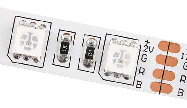
Simple
These are the “dumb” led strips, you can only control all the LEDS at once, you can controll the LEDS trough MOSFETS and PWM, you can recognize these strips when there are 4 channels and have resistors on them:
Schematic example:

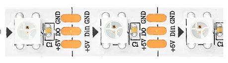
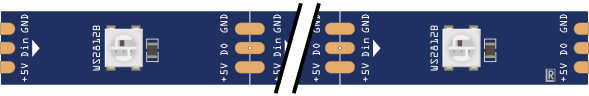
Smart
These are the smart led strips, you can only control every LED and make some cool effects, you can controll the LEDS DATA signals, you can recognize these strips when there are 3 channeld and have capacitors on them:
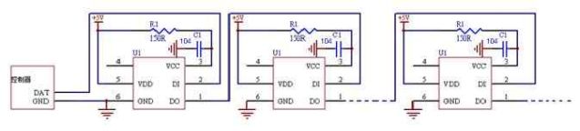
Schematic example:
Pinout
Simple led strips:
+ = VCC
R = Red channel
G = Green channel
B = Blue channel
Programmable led strips (W2812):
+ = VCC
– = GND
DI = Data IN
DO = Data Out
Arduino
Bron: https://learn.adafruit.com/rgb-led-strips/usage
Because these LED strips are very simple, we can easily use them with any microcontroller. We suggest using PWM dimming techniques to control the strip. Since each ‘LED’ pin may end up requiring an Amp or more to sink to ground, power transistors are required! Don’t try to connect the pins directly to your everyday microcontroller, they will burn out and/or not work.
You can use any power NPN or N-Channel MOSFET, make sure the transistor is rated to be able to pass as much current as you need. For example, since we draw about 0.2Amps per channel per meter, if you have a 5 meter strip you will need to pass up to 1 Ampere per transistor. Get the beefy “TO-220” packages, not the dinky little guys
For basic, low-cost usage we suggest using N-channel MOSFETs such as the IRLB8721 – they are very popular and inexpensive and work with 3.3V or 5V logic. If you can’t get those, TIP120 are also good but there is more voltage loss in a transistor than in a MOSFET which is why we suggest those first (less heat loss, more light!)
This diagram shows connecting up with N-Channel MOSFETs where the Gate is pin 1, the Drain is pin 2 and the Source is pin 3
The IRLB8721‘s can handle up to 16 Amps of continuous current – so that’s at least 750 LEDs, and if you don’t have them all on bright white, 1500 LEDs. You may need to heat sink depending on the continuous/overall power draw/dissipation
For longer strips requiring more than 1 Amp, wire the power directly to the strip, then run power and ground wires back to the Arduino.
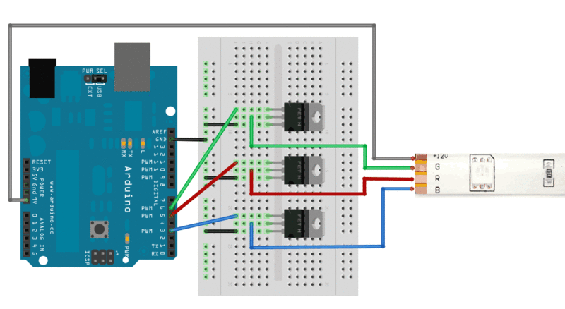
This diagram shows connecting up with power NPN transistors such as TIP120, where Base is pin 1, Collector is pin 2 and Emitter is pin 3. Its very similar except this time we have 100-220 ohm resistors between the PWM output pin and the base.

Connect a 9-12V power supply to the Arduino so that Vin supplies the high voltage to the LED strip. If you want, you can also just use a separate wire that connects to a power supply that provides about +12V. Make sure to connect the ground of that supply to the ground of the Arduino/MOSFETs!
TIP120’s can handle up to 5 Amps of continuous current – so that’s at least 250 LEDs, and if you don’t have them all on bright white, 500 LEDs.
Script
Once you have the strip wired up, it is easy to control the color of the strip by using PWM output, for Arduino you can use analogWrite() on pins 3, 5, 6, 9, 10 or 11 (for classic Arduinos using the Atmega328 or 168). An analogWrite(pin, 0) will turn that LED off, analogWrite(pin, 127) will turn it on half-way and analogWrite(pin, 255) will turn it on full blast. Here is some example code that performs a simple color-swirl.
|
1 2 3 4 5 6 7 8 9 10 11 12 13 14 15 16 17 18 19 20 21 22 23 24 25 26 27 28 29 30 31 32 33 34 35 36 37 38 39 40 41 42 43 44 45 46 47 48 49 50 51 |
// color swirl! connect an RGB LED to the PWM pins as indicated // in the #defines // public domain, enjoy! #define REDPIN 5 #define GREENPIN 6 #define BLUEPIN 3 #define FADESPEED 5 // make this higher to slow down void setup() { pinMode(REDPIN, OUTPUT); pinMode(GREENPIN, OUTPUT); pinMode(BLUEPIN, OUTPUT); } void loop() { int r, g, b; // fade from blue to violet for (r = 0; r < 256; r++) { analogWrite(REDPIN, r); delay(FADESPEED); } // fade from violet to red for (b = 255; b > 0; b--) { analogWrite(BLUEPIN, b); delay(FADESPEED); } // fade from red to yellow for (g = 0; g < 256; g++) { analogWrite(GREENPIN, g); delay(FADESPEED); } // fade from yellow to green for (r = 255; r > 0; r--) { analogWrite(REDPIN, r); delay(FADESPEED); } // fade from green to teal for (b = 0; b < 256; b++) { analogWrite(BLUEPIN, b); delay(FADESPEED); } // fade from teal to blue for (g = 255; g > 0; g--) { analogWrite(GREENPIN, g); delay(FADESPEED); } } |
Arduino Library
Installatie van Arduino IDE libraries: Arduino info
NEOPIXEL (TODO)
Afmetingen
GEEN GEGEVENS
Schema
Basic ledstrip channel controller with N-channel mosfet

Rin:
It is generally a good idea to include a gate resistor to avoid ringing. Ringing (parasitic oscillation) is caused by the gate capacitance in series with the connecting wire’s inductance and can cause the transistor to dissipate excessive power because it doesn’t turn on quickly enough and hence the current through drain/source in combination with the somewhat high’ish drain-source impedance will heat the device up. A low ohm resistor will solve (dampen) the ringing.
Typical: 100 Ohm
Rgs:
A high value resistor to ground is a good idea to avoid capacitive coupling driving the transistor when it is otherwise not connected.

Teardown
GEEN GEGEVENS
Datasheet
GEEN GEGEVENS
Fritzing
Downloads
GEEN GEGEVENS