Module – RC522 – RFID/NFC transciever
Hardware
Informatie (ENG)
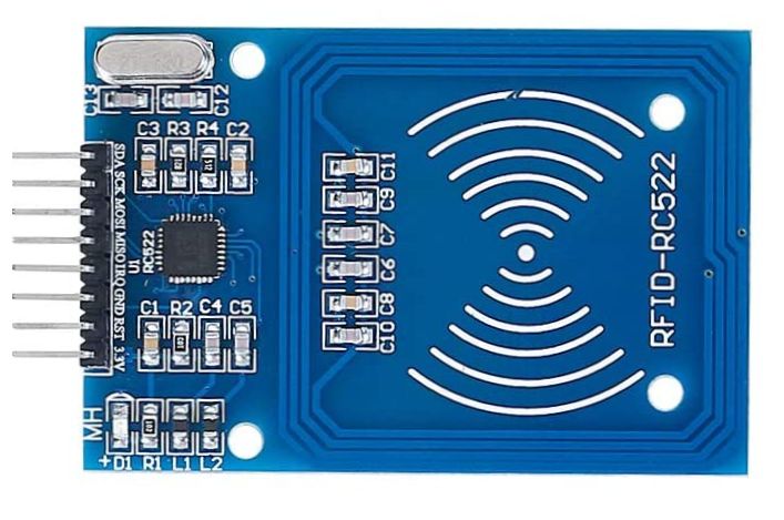
The RC522 RFID module based on MFRC522 IC from NXP is one of the most inexpensive RFID options that you can get online for less than four dollars. It usually comes with a RFID card tag and key fob tag having 1KB memory. And best of all, it can write a tag, so you can store your some sort of secret message in it.
The RC522 RFID Reader module is designed to create a 13.56MHz electromagnetic field that it uses to communicate with the RFID tags (ISO 14443A standard tags). The reader can communicate with a microcontroller over a 4-pin Serial Peripheral Interface (SPI) with a maximum data rate of 10Mbps. It also supports communication over I2C and UART protocols.
The module comes with an interrupt pin. It is handy because instead of constantly asking the RFID module “is there a card in view yet? “, the module will alert us when a tag comes into its vicinity.
The operating voltage of the module is from 2.5 to 3.3V, but the good news is that the logic pins are 5-volt tolerant, so we can easily connect it to an Arduino or any 5V logic microcontroller without using any logic level converter.
Here are complete specifications:
| Frequency Range | 13.56 MHz ISM Band |
| Host Interface | SPI / I2C / UART |
| Operating Supply Voltage | 2.5 V to 3.3 V |
| Max. Operating Current | 13-26mA |
| Min. Current(Power down) | 10µA |
| Logic Inputs | 5V Tolerant |
| Read Range | 5 cm |
Pinout
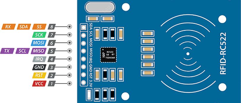
VCC supplies power for the module. This can be anywhere from 2.5 to 3.3 volts. You can connect it to 3.3V output from your Arduino. Remember connecting it to 5V pin will likely destroy your module!
RST is an input for Reset and power-down. When this pin goes low, hard power-down is enabled. This turns off all internal current sinks including the oscillator and the input pins are disconnected from the outside world. On the rising edge, the module is reset.
GND is the Ground Pin and needs to be connected to GND pin on the Arduino.
IRQ is an interrupt pin that can alert the microcontroller when RFID tag comes into its vicinity.
MISO / SCL / Tx pin acts as Master-In-Slave-Out when SPI interface is enabled, acts as serial clock when I2C interface is enabled and acts as serial data output when UART interface is enabled.
MOSI (Master Out Slave In) is SPI input to the RC522 module.
SCK (Serial Clock) accepts clock pulses provided by the SPI bus Master i.e. Arduino.
SS / SDA / Rx pin acts as Signal input when SPI interface is enabled, acts as serial data when I2C interface is enabled and acts as serial data input when UART interface is enabled. This pin is usually marked by encasing the pin in a square so it can be used as a reference for identifying the other pins.
Arduino
Sluit de module aan volgens onderstaand overzicht:
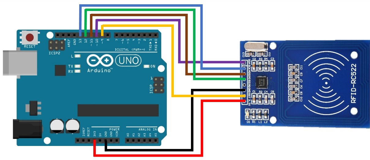
| Pin | Wiring to Arduino Uno |
| SDA | Digital 10 |
| SCK | Digital 13 |
| MOSI | Digital 11 |
| MISO | Digital 12 |
| IRQ | unconnected |
| GND | GND |
| RST | Digital 9 |
| 3.3V | 3.3V |
Script met bibliotheek
Wat heb je nodig?
1) RFID library here created by miguelbalboa
Example script from the library
|
1 2 3 4 5 6 7 8 9 10 11 12 13 14 15 16 17 18 19 20 21 22 23 24 25 26 27 28 29 30 31 32 |
#include <SPI.h> #include <MFRC522.h> #define RST_PIN 9 // Configurable, see typical pin layout above #define SS_PIN 10 // Configurable, see typical pin layout above MFRC522 mfrc522(SS_PIN, RST_PIN); // Create MFRC522 instance void setup() { Serial.begin(9600); // Initialize serial communications with the PC while (!Serial); // Do nothing if no serial port is opened (added for Arduinos based on ATMEGA32U4) SPI.begin(); // Init SPI bus mfrc522.PCD_Init(); // Init MFRC522 delay(4); // Optional delay. Some board do need more time after init to be ready, see Readme mfrc522.PCD_DumpVersionToSerial(); // Show details of PCD - MFRC522 Card Reader details Serial.println(F("Scan PICC to see UID, SAK, type, and data blocks...")); } void loop() { // Reset the loop if no new card present on the sensor/reader. This saves the entire process when idle. if ( ! mfrc522.PICC_IsNewCardPresent()) { return; } // Select one of the cards if ( ! mfrc522.PICC_ReadCardSerial()) { return; } // Dump debug info about the card; PICC_HaltA() is automatically called mfrc522.PICC_DumpToSerial(&(mfrc522.uid)); } |
Het resultaat NTAG chip
|
1 2 3 4 5 6 7 8 9 10 11 12 13 14 15 16 17 18 19 20 |
Card UID: 04 66 C0 7A 1C 23 80 Card SAK: 00 PICC type: MIFARE Ultralight or Ultralight C Page 0 1 2 3 0 04 66 C0 2A 1 7A 1C 23 80 2 C5 48 00 00 3 E1 10 12 00 4 01 03 A0 10 5 44 03 15 D1 6 01 11 55 01 7 6E 66 63 2D 8 6E 65 64 65 9 72 6C 61 6E 10 64 2E 6E 6C 11 FE 00 00 00 12 00 00 00 00 13 00 00 00 00 14 00 00 00 00 15 00 00 00 00 |
Het resultaat Mifare chip 1KB
|
1 2 3 4 5 6 7 8 9 10 11 12 13 14 15 16 17 18 19 20 21 22 23 24 25 26 27 28 29 30 31 32 33 34 35 36 37 38 39 40 41 42 43 44 45 46 47 48 49 50 51 52 53 54 55 56 57 58 59 60 61 62 63 64 65 66 67 68 |
Card UID: 24 7C F3 70 Card SAK: 08 PICC type: MIFARE 1KB Sector Block 0 1 2 3 4 5 6 7 8 9 10 11 12 13 14 15 AccessBits 15 63 00 00 00 00 00 00 FF 07 80 69 FF FF FF FF FF FF [ 0 0 1 ] 62 00 00 00 00 00 00 00 00 00 00 00 00 00 00 00 00 [ 0 0 0 ] 61 00 00 00 00 00 00 00 00 00 00 00 00 00 00 00 00 [ 0 0 0 ] 60 00 00 00 00 00 00 00 00 00 00 00 00 00 00 00 00 [ 0 0 0 ] 14 59 00 00 00 00 00 00 FF 07 80 69 FF FF FF FF FF FF [ 0 0 1 ] 58 00 00 00 00 00 00 00 00 00 00 00 00 00 00 00 00 [ 0 0 0 ] 57 00 00 00 00 00 00 00 00 00 00 00 00 00 00 00 00 [ 0 0 0 ] 56 00 00 00 00 00 00 00 00 00 00 00 00 00 00 00 00 [ 0 0 0 ] 13 55 00 00 00 00 00 00 FF 07 80 69 FF FF FF FF FF FF [ 0 0 1 ] 54 00 00 00 00 00 00 00 00 00 00 00 00 00 00 00 00 [ 0 0 0 ] 53 00 00 00 00 00 00 00 00 00 00 00 00 00 00 00 00 [ 0 0 0 ] 52 00 00 00 00 00 00 00 00 00 00 00 00 00 00 00 00 [ 0 0 0 ] 12 51 00 00 00 00 00 00 FF 07 80 69 FF FF FF FF FF FF [ 0 0 1 ] 50 00 00 00 00 00 00 00 00 00 00 00 00 00 00 00 00 [ 0 0 0 ] 49 00 00 00 00 00 00 00 00 00 00 00 00 00 00 00 00 [ 0 0 0 ] 48 00 00 00 00 00 00 00 00 00 00 00 00 00 00 00 00 [ 0 0 0 ] 11 47 00 00 00 00 00 00 FF 07 80 69 FF FF FF FF FF FF [ 0 0 1 ] 46 00 00 00 00 00 00 00 00 00 00 00 00 00 00 00 00 [ 0 0 0 ] 45 00 00 00 00 00 00 00 00 00 00 00 00 00 00 00 00 [ 0 0 0 ] 44 00 00 00 00 00 00 00 00 00 00 00 00 00 00 00 00 [ 0 0 0 ] 10 43 00 00 00 00 00 00 FF 07 80 69 FF FF FF FF FF FF [ 0 0 1 ] 42 00 00 00 00 00 00 00 00 00 00 00 00 00 00 00 00 [ 0 0 0 ] 41 00 00 00 00 00 00 00 00 00 00 00 00 00 00 00 00 [ 0 0 0 ] 40 00 00 00 00 00 00 00 00 00 00 00 00 00 00 00 00 [ 0 0 0 ] 9 39 00 00 00 00 00 00 FF 07 80 69 FF FF FF FF FF FF [ 0 0 1 ] 38 00 00 00 00 00 00 00 00 00 00 00 00 00 00 00 00 [ 0 0 0 ] 37 00 00 00 00 00 00 00 00 00 00 00 00 00 00 00 00 [ 0 0 0 ] 36 00 00 00 00 00 00 00 00 00 00 00 00 00 00 00 00 [ 0 0 0 ] 8 35 00 00 00 00 00 00 FF 07 80 69 FF FF FF FF FF FF [ 0 0 1 ] 34 00 00 00 00 00 00 00 00 00 00 00 00 00 00 00 00 [ 0 0 0 ] 33 00 00 00 00 00 00 00 00 00 00 00 00 00 00 00 00 [ 0 0 0 ] 32 00 00 00 00 00 00 00 00 00 00 00 00 00 00 00 00 [ 0 0 0 ] 7 31 00 00 00 00 00 00 FF 07 80 69 FF FF FF FF FF FF [ 0 0 1 ] 30 00 00 00 00 00 00 00 00 00 00 00 00 00 00 00 00 [ 0 0 0 ] 29 00 00 00 00 00 00 00 00 00 00 00 00 00 00 00 00 [ 0 0 0 ] 28 00 00 00 00 00 00 00 00 00 00 00 00 00 00 00 00 [ 0 0 0 ] 6 27 00 00 00 00 00 00 FF 07 80 69 FF FF FF FF FF FF [ 0 0 1 ] 26 00 00 00 00 00 00 00 00 00 00 00 00 00 00 00 00 [ 0 0 0 ] 25 00 00 00 00 00 00 00 00 00 00 00 00 00 00 00 00 [ 0 0 0 ] 24 00 00 00 00 00 00 00 00 00 00 00 00 00 00 00 00 [ 0 0 0 ] 5 23 00 00 00 00 00 00 FF 07 80 69 FF FF FF FF FF FF [ 0 0 1 ] 22 00 00 00 00 00 00 00 00 00 00 00 00 00 00 00 00 [ 0 0 0 ] 21 00 00 00 00 00 00 00 00 00 00 00 00 00 00 00 00 [ 0 0 0 ] 20 00 00 00 00 00 00 00 00 00 00 00 00 00 00 00 00 [ 0 0 0 ] 4 19 00 00 00 00 00 00 FF 07 80 69 FF FF FF FF FF FF [ 0 0 1 ] 18 00 00 00 00 00 00 00 00 00 00 00 00 00 00 00 00 [ 0 0 0 ] 17 00 00 00 00 00 00 00 00 00 00 00 00 00 00 00 00 [ 0 0 0 ] 16 00 00 00 00 00 00 00 00 00 00 00 00 00 00 00 00 [ 0 0 0 ] 3 15 00 00 00 00 00 00 FF 07 80 69 FF FF FF FF FF FF [ 0 0 1 ] 14 00 00 00 00 00 00 00 00 00 00 00 00 00 00 00 00 [ 0 0 0 ] 13 00 00 00 00 00 00 00 00 00 00 00 00 00 00 00 00 [ 0 0 0 ] 12 00 00 00 00 00 00 00 00 00 00 00 00 00 00 00 00 [ 0 0 0 ] 2 11 00 00 00 00 00 00 FF 07 80 69 FF FF FF FF FF FF [ 0 0 1 ] 10 00 00 00 00 00 00 00 00 00 00 00 00 00 00 00 00 [ 0 0 0 ] 9 00 00 00 00 00 00 00 00 00 00 00 00 00 00 00 00 [ 0 0 0 ] 8 00 00 00 00 00 00 00 00 00 00 00 00 00 00 00 00 [ 0 0 0 ] 1 7 00 00 00 00 00 00 FF 07 80 69 FF FF FF FF FF FF [ 0 0 1 ] 6 00 00 00 00 00 00 00 00 00 00 00 00 00 00 00 00 [ 0 0 0 ] 5 00 00 00 00 00 00 00 00 00 00 00 00 00 00 00 00 [ 0 0 0 ] 4 00 00 00 00 00 00 00 00 00 00 00 00 00 00 00 00 [ 0 0 0 ] 0 3 00 00 00 00 00 00 FF 07 80 69 FF FF FF FF FF FF [ 0 0 1 ] 2 00 00 00 00 00 00 00 00 00 00 00 00 00 00 00 00 [ 0 0 0 ] 1 00 00 00 00 00 00 00 00 00 00 00 00 00 00 00 00 [ 0 0 0 ] 0 24 7C F3 70 DB 08 04 00 62 63 64 65 66 67 68 69 [ 0 0 0 ] |
Script with specific UID access
|
1 2 3 4 5 6 7 8 9 10 11 12 13 14 15 16 17 18 19 20 21 22 23 24 25 26 27 28 29 30 31 32 33 34 35 36 37 38 39 40 41 42 43 44 45 46 47 48 49 50 51 52 53 54 55 56 57 58 59 60 61 62 63 |
/* * * All the resources for this project: https://randomnerdtutorials.com/ * Modified by Rui Santos * * Created by FILIPEFLOP * */ #include <SPI.h> #include <MFRC522.h> #define SS_PIN 10 #define RST_PIN 9 MFRC522 mfrc522(SS_PIN, RST_PIN); // Create MFRC522 instance. void setup() { Serial.begin(9600); // Initiate a serial communication SPI.begin(); // Initiate SPI bus mfrc522.PCD_Init(); // Initiate MFRC522 Serial.println("Approximate your card to the reader..."); Serial.println(); } void loop() { // Look for new cards if ( ! mfrc522.PICC_IsNewCardPresent()) { return; } // Select one of the cards if ( ! mfrc522.PICC_ReadCardSerial()) { return; } //Show UID on serial monitor Serial.print("UID tag :"); String content= ""; byte letter; for (byte i = 0; i < mfrc522.uid.size; i++) { Serial.print(mfrc522.uid.uidByte[i] < 0x10 ? " 0" : " "); Serial.print(mfrc522.uid.uidByte[i], HEX); content.concat(String(mfrc522.uid.uidByte[i] < 0x10 ? " 0" : " ")); content.concat(String(mfrc522.uid.uidByte[i], HEX)); } Serial.println(); Serial.print("Message : "); content.toUpperCase(); if (content.substring(1) == "BD 31 15 2B") //change here the UID of the card/cards that you want to give access { Serial.println("Authorized access"); Serial.println(); delay(3000); } else { Serial.println(" Access denied"); delay(3000); } } |
Bronnen:
https://lastminuteengineers.com/how-rfid-works-rc522-arduino-tutorial/
https://randomnerdtutorials.com/security-access-using-mfrc522-rfid-reader-with-arduino/
Arduino Library
Installatie van Arduino IDE libraries: Arduino info
Arduino library for MFRC522 and other RFID RC522 based modules.
Read and write different types of Radio-Frequency IDentification (RFID) cards on your Arduino using a RC522 based reader connected via the Serial Peripheral Interface (SPI) interface.
What works and not?
- Works
- Communication (Crypto1) with MIFARE Classic (1k, 4k, Mini).
- Communication (Crypto1) with MIFARE Classic compatible PICCs.
- Firmware self check of MFRC522.
- Set the UID, write to sector 0, and unbrick Chinese UID changeable MIFARE cards.
- Manage the SPI chip select pin (aka SS, SDA)
- Works partially
- Communication with MIFARE Ultralight.
- Other PICCs (Ntag216).
- More than 2 modules, require a multiplexer #191.
- Doesn’t work
- MIFARE DESFire, MIFARE DESFire EV1/EV2, not supported by software.
- Communication with 3DES or AES, not supported by software.
- Peer-to-peer (ISO/IEC 18092), not supported by hardware.
- Communication with smart phone, not supported by hardware.
- Card emulation, not supported by hardware.
- Use of IRQ pin. But there is a proof-of-concept example.
- With Intel Galileo (Gen2) see #310, not supported by software.
- Power reduction modes #269, not supported by software.
- I2C instead of SPI #240, not supported by software.
- UART instead of SPI #281, not supported by software.
- Need more?
- If software: code it and make a pull request.
- If hardware: buy a more expensive like PN532 (supports NFC and many more, but costs about $15 and not usable with this library).
Hardware
There are three hardware components involved:
- Micro Controller:
- An Arduino or compatible executing the Sketch using this library.
- Prices vary from USD 7 for clones, to USD 75 for “starter kits” (which might be a good choice if this is your first exposure to Arduino; check if such kit already includes the Arduino, Reader, and some Tags).
- Proximity Coupling Device (PCD):
- The PCD is the actual RFID Reader based on the NXP MFRC522 Contactless Reader Integrated Circuit.
- Readers can be found on eBay for around USD 5: search for “rc522”.
- You can also find them on several web stores. They are often included in “starter kits”, so check your favourite electronics provider as well.
- Proximity Integrated Circuit Card (PICC):
- The PICC is the RFID Card or Tag using the ISO/IEC 14443A interface, for example Mifare or NTAG203.
- One or two might be included with the Reader or “starter kit” already.
Protocols
- The micro controller and the reader use SPI for communication.
- The protocol is described in the NXP MFRC522 datasheet.
- See the Pin Layout section for details on connecting the pins.
- The reader and the tags communicate using a 13.56 MHz electromagnetic field.
- The protocol is defined in ISO/IEC 14443-3:2011 Part 3 Type A.
- Details are found in chapter 6 “Type A – Initialization and anticollision”.
- See http://wg8.de/wg8n1496_17n3613_Ballot_FCD14443-3.pdf for a free version of the final draft (which might be outdated in some areas).
- The reader does not support ISO/IEC 14443-3 Type B.
Security
- The UID of a card can not be used as an unique identification for security related projects. Some Chinese cards allow to change the UID which means you can easily clone a card. For projects like access control, door opener or payment systems you must implement an additional security mechanism like a password or normal key.
- This library only supports crypto1-encrypted communication. Crypto1 has been known as broken for a few years, so it does NOT offer ANY security, it is virtually unencrypted communication. Do not use it for any security related applications!
- This library does not offer 3DES or AES authentication used by cards like the Mifare DESFire, it may be possible to be implemented because the datasheet says there is support. We hope for pull requests :).
Download bibliotheek @ https://github.com/miguelbalboa/rfid/
Raspberry Pi
Sluit de module aan volgens onderstaand overzicht:
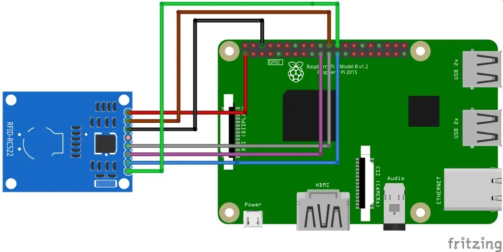
| RFID pin | RPI pin | Functie | Kabel |
|---|---|---|---|
| SDA | 24 | CE0 | Groen |
| SCK | 23 | SCLK | Blauw |
| MOSI | 19 | SPI MOSI | Paars |
| MISO | 21 | SPI MISO | Grijs |
| IRQ | – | – | – |
| Gnd | 6 | Gnd | Zwart |
| RST | 22 | GPIO 25 | Bruin |
| 3.3V | 1 | 3.3V | Rood |
SPI activeren
Voor de communicatie met de RFID lezer maken we gebruik we de SPI interface, deze dien je via raspi-config te activeren.
|
1 |
raspi-config |
Ga in het menu naar ‘Advanced Options’, selecteer de optie ‘SPI’ en activeer de interface.
Herstart hierna je Raspberry Pi:
|
1 |
sudo reboot -h 0 |
SPI Python libraries
Voordat Python met de SPI interface en RFID lezer kan communiceren hebben we een aantal Python libraries nodig, alleerst de Python Developer library.
|
1 |
sudo apt-get install python-dev |
Hierna gaan we SPI-Py downloaden vanaf GitHub:
|
1 |
git clone https://github.com/lthiery/SPI-Py.git |
Nadat library is gecloond vanaf GitHub moeten we SPI-Py toevoegen aan Python:
|
1 |
sudo python setup.py install |
Python script voor de RC522 RFID lezer
We hebben nu via Python toegang tot de SPI interface. Als laatste hebben we een script nodig dat de tags kan uitlezen, hiervoor maken we gebruik van MFRC522-python. Download het script vanaf GitHub:
|
1 |
git clone https://github.com/mxgxw/MFRC522-python.git |
Ga naar de map (MFRC522-python) waarin de GitHub bestanden zijn geplaatst:
|
1 |
cd MFRC522-python |
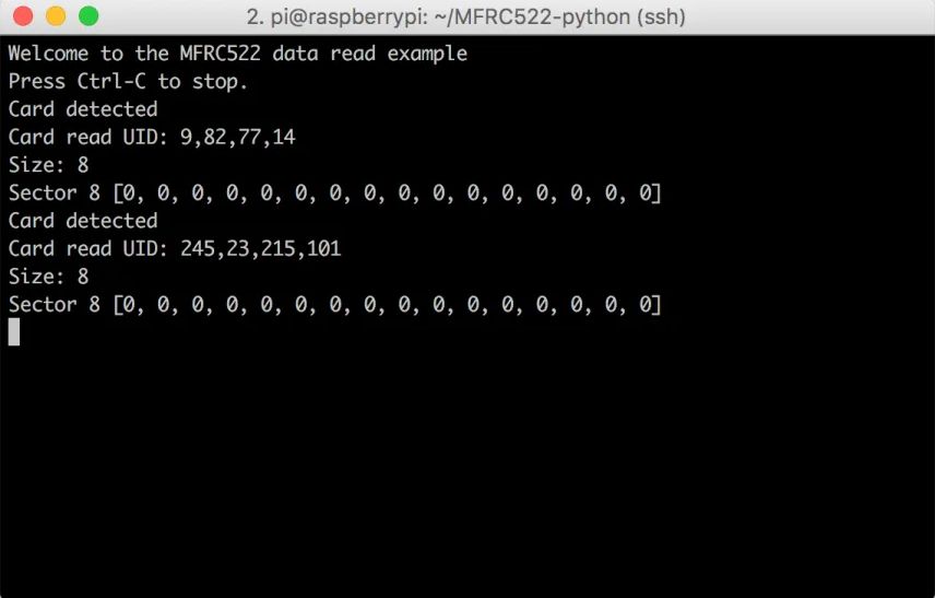
Gebruikt het Read.py script om de tags te lezen:
|
1 |
python Read.py |
Bron(nen):
Raspberry Pi Library
SPI-Py: Hardware SPI as a C Extension for Python
COPYRIGHT (C) 2012 Louis Thiery. All rights reserved. Further work by Connor Wolf.
Forked in 2019 by Nathan Leefer to fix memory handling in the C extension.
This program is free software; you can redistribute it and/or modify it under the terms of the GNU General Public License V2 as published by the Free Software Foundation.
LIABILITY
This program is distributed for educational purposes only and is no way suitable for any particular application, especially commercial. There is no implied suitability so use at your own risk!
Instructions
- Clone or download this repository, navigate to the SPI-Py directory, and install the library using the following command. Use python3 if installing for Python 3.
|
1 |
> sudo python setup.py install |
- Make sure the SPI interface is enabled for your Raspberry Pi. This can be done using the raspi-config utility.
|
1 |
> sudo raspi-config |
- This module provides three functions for communicating with SPI devices:
|
1 2 3 |
dev_dictionary = spi.openSPI(kwargs) data_in = spi.transfer(dev_dictionary, data_out) spi.closeSPI(dev_dictionary) |
The next section covers these in detail.
Example usage
The below commands can be found in the test_script.py file.
After installing the library, import the spi module to your Python code via :
|
1 |
import spi |
Open the file descriptor to the SPI device with one of two chip selects:
|
1 |
device_0 = spi.openSPI(device="/dev/spidev0.0",mode=0,speed=500000,bits=8,delay=0) |
The device keyword can be either “/dev/spidev0.0” or “/dev/spidev0.1”. The difference refers to which chip select pin is used by the SPI device driver. The mode keyword can be 0,1,2, or 3, and many SPI devices can operate up to 8000000 Hz speed, however it is recommended to check your data sheet. See the Raspberry Pi docs for a detailed explanation of these and other parameters.
Use the returned device handle to conduct an SPI transaction
|
1 2 3 |
data_out = (0xFF,0x00,0xFF) data_in = (0x00, 0x00, 0x00) data_in = spi.transfer(device_0, data_out) |
The above would write the 3 bytes contained in data_out and copy the received data to data_in. Note that data_in will always be a tuple the same length as data_out, and will simply reflect the state of the MISO pin throughout the transaction. It is up to the user to understand the device behavior connected to the SPI pins.
To verify that this works connect GPIO 10 (MOSI, physical pin 19) to GPIO 9 (MISO, physical pin 21) in a loop back. You should see that data_out now equals data_in.
Close the file descriptor for your SPI device
|
1 |
spi.closeSPI(device_0) |
Memory leak
The memory_leak.py script continuously executes a simple transaction on /dev/spidev0.0. There does not appear to be a memory leak in this use case.
Download @ https://github.com/lthiery/SPI-Py
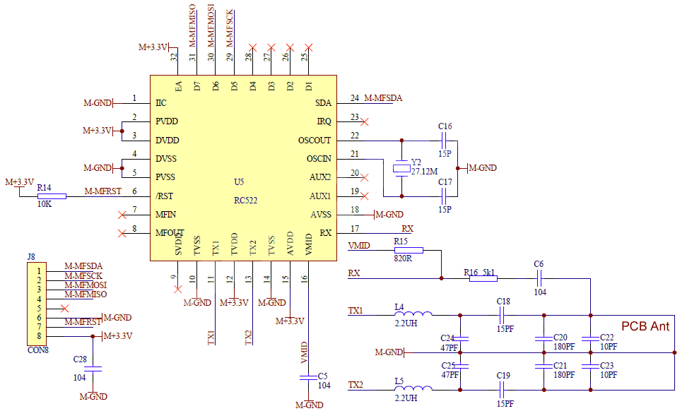
Schema
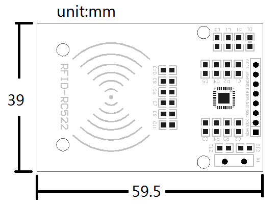
Afmetingen
Teardown
GEEN GEGEVENS
Datasheet
Fritzing

Downloads
GEEN GEGEVENS