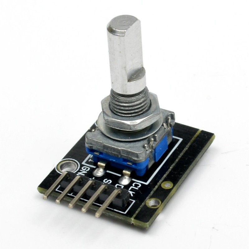
Module – Rotary encoder
Hardware

|
1 2 3 4 5 6 7 |
Position Bit1 Bit2 - - - - - - - - - - - Step1 0 0 1/4 1 0 1/2 1 1 3/4 0 1 Step2 0 0 |
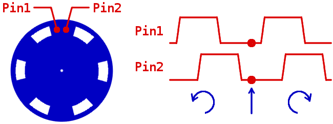
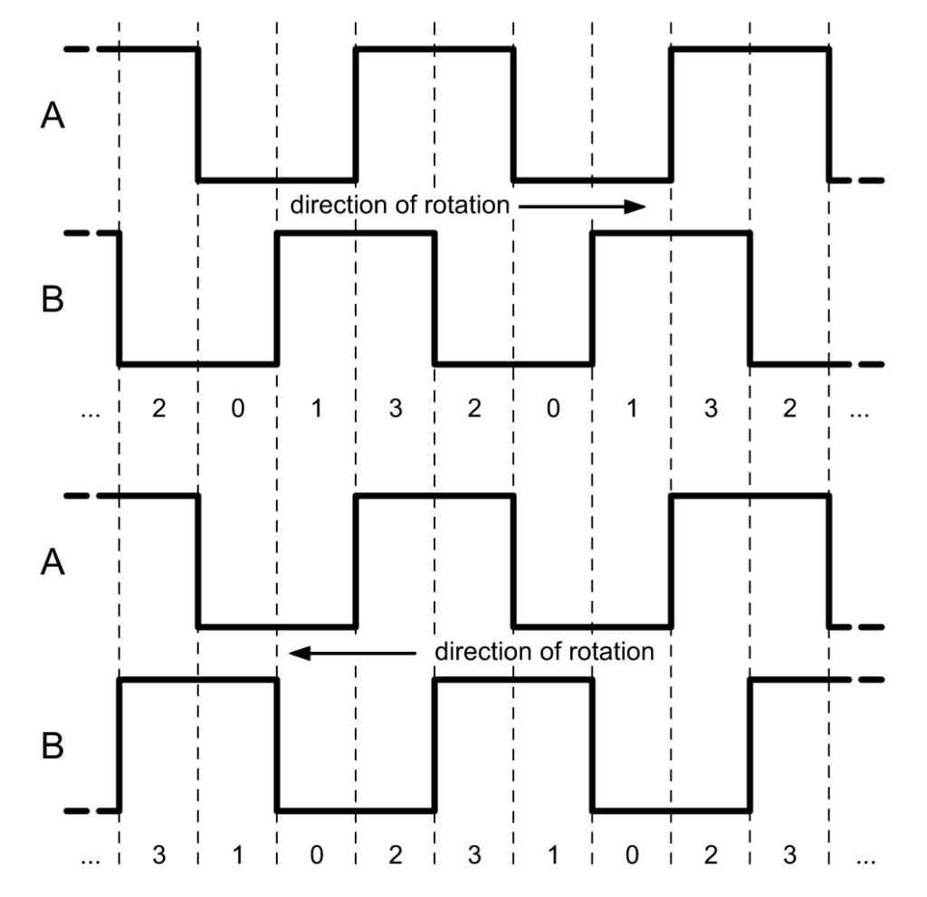
Rotating the encoder one step takes the signal a full period, starting at A and B both in the HIGH state, both changing to LOW, and both changing back to HIGH again. If you apply the logic on both transitions, you will do a double +1 for every clock-wise transition:
1. A and B are both HIGH (initial state)
2. A changes to LOW, B is still HIGH, so +1 because A changed and B != A
3. B changes to LOW, no effect
4. A and B are now both LOW
5. A changes back to HIGH, B is still LOW, so +1 because A changed and B != A
6. B changes to HIGH, no effect
7. A and B are both HIGH (final state)
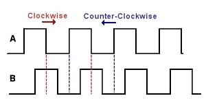
For every counter-clock-wise transition, you will instead do -1 twice:
1. A and B are both HIGH (initial state)
2. B changes to LOW, no effect
3. A changes to LOW, B is already LOW, so -1 because A changed and B == A
4. A and B are now both LOW
6. B changes to HIGH, no effect
5. A changes back to HIGH, B is already HIGH, so -1 because A changed and B == A
7. A and B are both HIGH (final state)
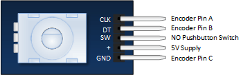
Pinout (Keyes KY-040 module)
 | |
|---|---|
| Pin: | Functie: |
| 1 | GND |
| 2 | +5V |
| 3 | SW (Schakelaar) |
| 4 | DT (Data puls) |
| 5 | CLK (Klok puls) |
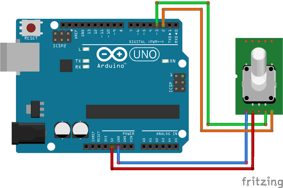
Aansluiten
Sluit de module aan volgens onderstaand schema:
| Rotary Encoder pin: | Arduino Pin: |
|---|---|
| 1 (GND) | GND |
| 2 (+) | +5V |
| 4 (DT) | 3 |
| 5 (CLK) | 2 |
Polling of Interrupts?
Je kan de Rotary Encoder op 2 manieren uitlezen: polling of met interrupts.
Polling
Polling doe je door de stand of beweging van de encoder uit te lezen in de LOOP, het nadeel hiervan is dat je tijdens de loop niet veel kan doen omdat dat de telling verstoord en de pulsen niet goed geteld worden, met polling is het wellicht wel mogelijk om meerdere Enscoders aan te sluiten op een Arduino UNO.
Interrupts
Met interrupts kun je een vallende of stijgende puls waarnemen en een subroutine laten uitvoeren die dan de pulsen telt, op deze manier is het tellen van de pulsen veel nauwkeuriger, het nadeel is dat je 2 interrupts nodig hebt per encoder en dus maar 1 kan aansluiten op een Arduino UNO (3 op de MEGA).
Ps. Bij de Keyes module is 1 “klik/stap” 4 pulsen/tellingen.
Script #1 Polling
|
1 2 3 4 5 6 7 8 9 10 11 12 13 14 15 16 17 18 19 20 21 22 23 24 25 26 27 28 29 30 31 32 33 34 35 36 37 38 39 40 41 42 43 44 45 46 47 48 49 50 51 52 53 54 55 56 57 58 59 60 61 62 63 64 65 66 67 68 69 70 71 72 |
// Rotary Encoder Inputs #define CLK 2 #define DT 3 #define SW 4 int counter = 0; int currentStateCLK; int lastStateCLK; String currentDir =""; unsigned long lastButtonPress = 0; void setup() { // Set encoder pins as inputs pinMode(CLK,INPUT); pinMode(DT,INPUT); pinMode(SW, INPUT_PULLUP); // Setup Serial Monitor Serial.begin(9600); // Read the initial state of CLK lastStateCLK = digitalRead(CLK); } void loop() { // Read the current state of CLK currentStateCLK = digitalRead(CLK); // If last and current state of CLK are different, then pulse occurred // React to only 1 state change to avoid double count if (currentStateCLK != lastStateCLK && currentStateCLK == 1){ // If the DT state is different than the CLK state then // the encoder is rotating CCW so decrement if (digitalRead(DT) != currentStateCLK) { counter --; currentDir ="CCW"; } else { // Encoder is rotating CW so increment counter ++; currentDir ="CW"; } Serial.print("Direction: "); Serial.print(currentDir); Serial.print(" | Counter: "); Serial.println(counter); } // Remember last CLK state lastStateCLK = currentStateCLK; // Read the button state int btnState = digitalRead(SW); //If we detect LOW signal, button is pressed if (btnState == LOW) { //if 50ms have passed since last LOW pulse, it means that the //button has been pressed, released and pressed again if (millis() - lastButtonPress > 50) { Serial.println("Button pressed!"); } // Remember last button press event lastButtonPress = millis(); } // Put in a slight delay to help debounce the reading delay(1); } |
Script #2 “INTERRUPT”
Onderstaand script leest de encoder uit via een interrupt subroutine en geeft de waarde weer via de console:
|
1 2 3 4 5 6 7 8 9 10 11 12 13 14 15 16 17 18 19 20 21 22 23 24 25 26 27 28 29 30 31 32 33 34 35 36 37 38 39 40 41 42 43 44 45 46 47 48 49 50 51 52 53 54 55 56 57 58 |
/* roto_jw4.ino -- JW, 29 September 2015 -- * A 4-state state-machine implementation of rotary * encoding for KY-040 rotary knobs. The state-machine picture at * https://e2e.ti.com/support/microcontrollers/hercules/f/312/t/318762 * in a Feb 4, 2014 7:40 PM post by Anthony Seely shows counts * increasing on transitions 10 -> 11 -> 01 -> 00 -> 10 and * decreasing on transitions the other way. Transitions between 00 * and 11 or 10 and 01 are invalid. This code detects valid * transitions by (abOld xor abNew) equaling 1 or 2. It detects * up-count events by the tri-bit value ABA' (where A' is the new * reading on pin A) being equal to 1, 2, 5, or 6 (a bit mask of * 0x66), and down-count events by ABA' being equal to 0, 3, 4, or 7 * (a bit mask of 0x99). * * On a KY-040 unit I tested, there are 30 detent positions per turn. * With this unit the code generates 60 counts per turn, which can be * seen individually as one turns the rotor slowly. Odd counts * appear between detents, even counts at detents. * * Set quadrature-signal pin numbers, via PinA and PinB constants. * Set IPINMODE to INPUT_PULLUP if there are no external pull-ups * on encoder AB pins, else set IPINMODE to INPUT */ enum { PinA=2, PinB=3, IPINMODE=INPUT }; static byte abOld; // Initialize state volatile int count; // current rotary count int old_count; // old rotary count void setup() { pinMode(PinA, IPINMODE); pinMode(PinB, IPINMODE); attachInterrupt(0, pinChangeISR, CHANGE); // Set up pin-change interrupts attachInterrupt(1, pinChangeISR, CHANGE); abOld = count = old_count = 0; Serial.begin(9600); Serial.println("Starting Rotary Encoder Test"); } // On interrupt, read input pins, compute new state, and adjust count void pinChangeISR() { enum { upMask = 0x66, downMask = 0x99 }; byte abNew = (digitalRead(PinA) << 1) | digitalRead(PinB); byte criterion = abNew^abOld; if (criterion==1 || criterion==2) { if (upMask & (1 << (2*abOld + abNew/2))) count--; else count++; // upMask = ~downMask } abOld = abNew; // Save new state } void loop() { if (old_count != count) { Serial.println(count); old_count = count; } } |
Output
|
1 2 3 4 5 6 7 8 9 10 11 12 13 14 15 16 17 18 19 |
Starting Rotary Encoder Test 1 2 3 4 5 6 7 8 9 10 11 12 13 14 15 14 13 12 |
Script #3 “POLLING” met bibliotheek
Wat heb je nodig?
1) Arduino Rotary encoder bibliotheek
|
1 2 3 4 5 6 7 8 9 10 11 12 13 14 15 16 17 18 19 20 21 22 23 |
#include <Encoder.h> // Change these two numbers to the pins connected to your encoder. // Best Performance: both pins have interrupt capability // Good Performance: only the first pin has interrupt capability // Low Performance: neither pin has interrupt capability Encoder myEnc(2, 3); // avoid using pins with LEDs attached void setup() { Serial.begin(9600); Serial.println("Basic Encoder Test:"); } long oldPosition = -999; void loop() { long newPosition = myEnc.read(); if (newPosition != oldPosition) { oldPosition = newPosition; Serial.println(newPosition); } } |
Output
|
1 2 3 4 5 6 7 8 9 10 11 12 13 14 15 16 17 18 19 20 21 22 |
Basic Encoder Test: 0 1 2 3 4 5 6 7 8 9 10 11 10 11 12 13 14 13 14 15 14 |
Script #4 “POLLING”
Onderstaand vind je een eenvoudig script zonder bibliotheken (bron g7nbp.blogspot.nl)
|
1 2 3 4 5 6 7 8 9 10 11 12 13 14 15 16 17 18 19 20 21 22 23 24 25 26 27 28 29 |
int clock = 2; // Define encoder pin A int data = 3; // Define encoder pin B int count = 0; // pre-init the count to zero int c = LOW; // pre-init the state of pin A low int cLast = LOW; // and make its last val the same - ie no change int d = LOW; // and make the data val low as well void setup() { pinMode (clock,INPUT); // setup the pins as inputs pinMode (data,INPUT); Serial.begin (9600); // and give some serial debugging } void loop() { c = digitalRead(clock); // read pin A as clock d = digitalRead(data); // read pin B as data if (c != cLast) { // clock pin has changed value... now we can do stuff d = c^d; // work out direction using an XOR if ( d ) { count--; // non-zero is Anti-clockwise }else{ count++; // zero is therefore anti-clockwise } Serial.print ("Jog:: count:"); Serial.println(count); cLast = c; // store current clock state for next pass } } |
Output
|
1 2 3 4 5 6 7 8 9 10 11 12 13 14 15 16 17 18 19 |
Jog:: count:-1 Jog:: count:0 Jog:: count:1 Jog:: count:2 Jog:: count:1 Jog:: count:2 Jog:: count:3 Jog:: count:4 Jog:: count:5 Jog:: count:4 Jog:: count:5 Jog:: count:4 Jog:: count:3 Jog:: count:2 Jog:: count:1 Jog:: count:0 Jog:: count:-1 Jog:: count:-2 Jog:: count:-3 |
Voorbeeld met weerstanden
Bron: https://www.elektormagazine.nl/labs/rotary-encoder-on-a-single-mcu-pin
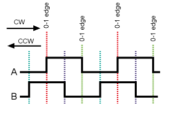
Determining the spinning direction
Spinning a properly wired rotary encoder produces a series of pulses on its A & B pins. To determine the spinning direction from these two signals all that is needed is to delay one of them by one step and then EXOR the two together.
Example
Suppose ‘A’ = ‘00110011…’ and ‘B’ = ‘01100110…’, then delay signal ‘A’, say, by one step to get ‘01100110…’. EXOR-ing the delayed ‘A’ with ‘B’ gives ‘00000000…’. When it is spinning in the other direction, then ‘A’ = ‘11001100…’ (‘B’ unchanged), and ‘A’ delayed by one step is ‘10011001…’. EXOR-ing the delayed ‘A’ with ‘B’ now gives ‘11111111…’.
Make it analog
Looking at the signals ‘A’ and ‘B’ together as a parallel bus allows us to consider them as a 2-bit binary value that can take on four values: 0b00, 0b01, 0b10 and 0b11 (Grey code). Multi-bit binary values can be converted to a single analog voltage using a digital-to-analog converter (DAC). That is what we will do here.
R-2R resistor network
A common, simple DAC can be built with a so-called R-2R resistor network. Such a network consists of a bunch of resistors with only two values: R and 2R. For each bit two resistors are needed, every extra bit adds two resistors. A 2-pin rotary encoder therefore needs four resistors.
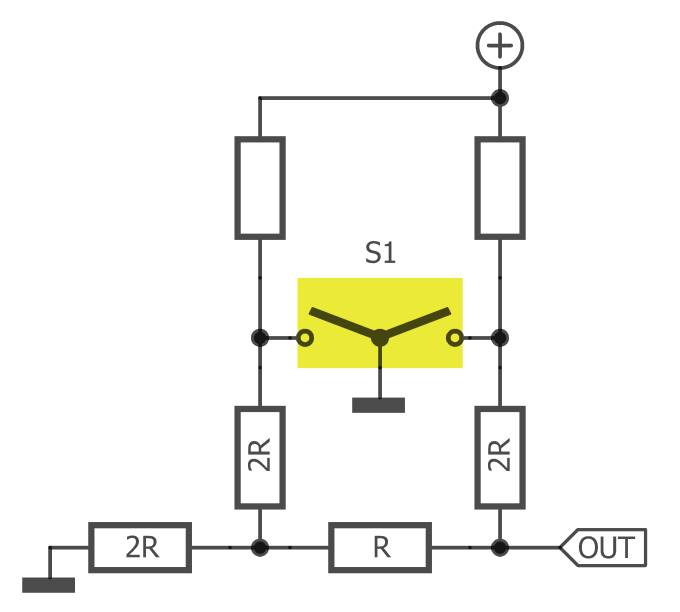
Such a circuit produces an analog voltage that takes on four values. The signal can be sampled with an AD converter and then decoded to recover the signals ‘A’ and ‘B’. These can then be processed further in the same way as for a “normal” rotary encoder.
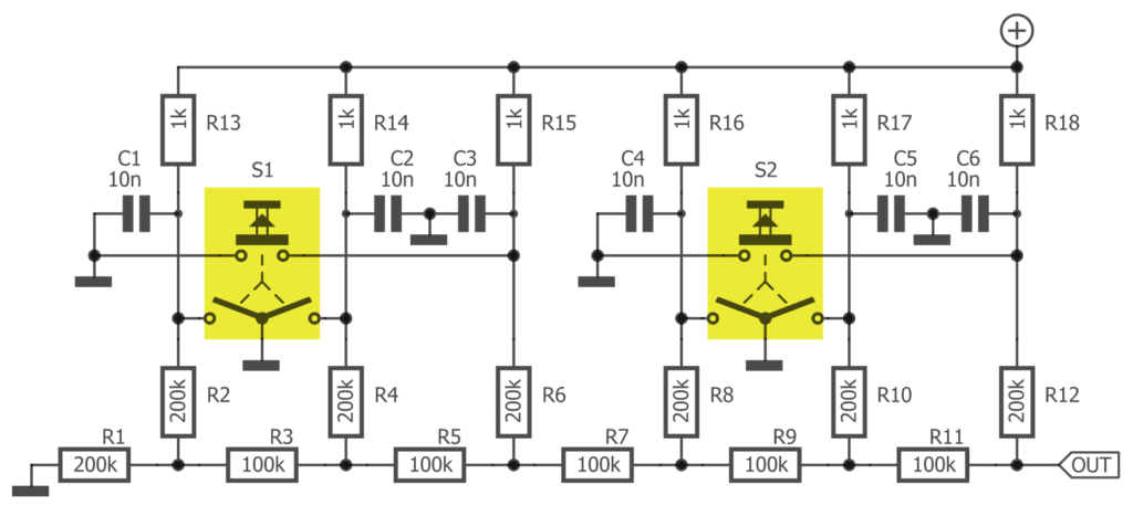
A practical implementation
Two rotary encoders with integrated pushbuttons require a 6-bit DA converter. A microcontroller with a built-in 10-bit AD converter can easily decode the composite signal as it will have a 4-bit margin per bit, allowing the use of 5% resistors (1% would be better of course). Suitable microcontrollers are abundant, for instance the ATmega328 as found on an Arduino Uno board.
In a real-life implementation the value of R in the R-2R network must be much larger than the pull-up resistors to avoid the latter from influencing the R-2R ratio too much. At the same time, the pull-ups must not be too small, otherwise the current flowing through the switch contacts would be too high.
2R resistors are simply two R resistors in series.
Capacitors are needed to debounce the mechanical contacts to avoid that might otherwise cause interference between the two encoders.
Bronnen:
arduino.stackexchange.com
heliosoph.mit-links.info
henrysbench.capnfatz.com
martoparts.nl
playground.arduino.cc