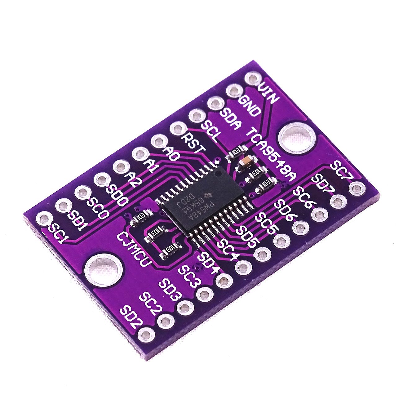
Module – TCA9548A – I2C multiplexer
Hardware
Informatie (ENG)
Description
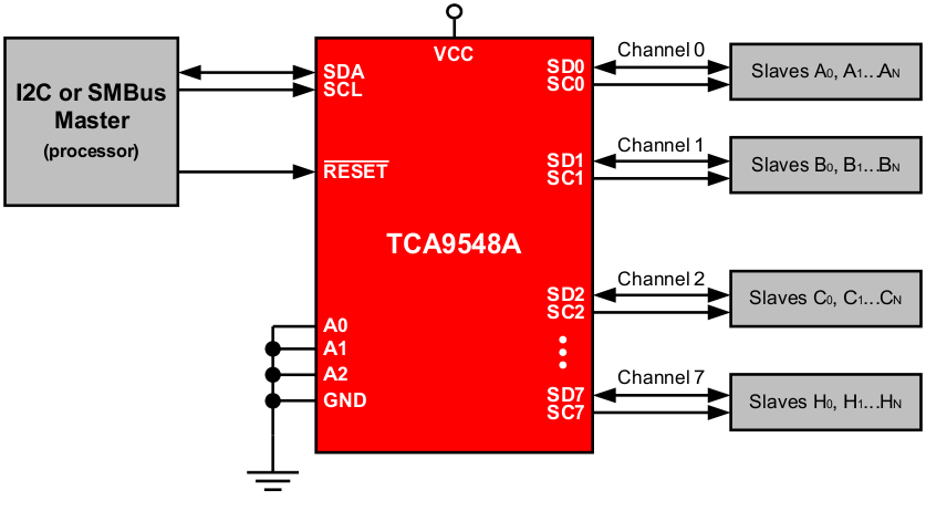
The TCA9548A device has eight bidirectional translating switches that can be controlled through the I2C bus. The SCL/SDA upstream pair fans out to eight downstream pairs, or channels. Any individual SCn/SDn channel or combination of channels can be selected, determined by the contents of the programmable control register. These downstream channels can be used to resolve I2C slave address conflicts. For example, if eight identical digital temperature sensors are needed in the application, one sensor can be connected at each channel: 0-7.
The system master can reset the TCA9548A in the event of a time-out or other improper operation by asserting a low in the RESET input. Similarly, the power-on reset deselects all channels and initializes the I2C/SMBus state machine. Asserting RESET causes the same reset and initialization to occur without powering down the part. This allows recovery should one of the downstream I2C buses get stuck in a low state.
The pass gates of the switches are constructed so that the VCC pin can be used to limit the maximum high voltage, which is passed by the TCA9548A. Limiting the maximum high voltage allows the use of different bus voltages on each pair, so that 1.8-V, 2.5-V or 3.3-V parts can communicate with 5-V parts, without any additional protection. External pullup resistors pull the bus up to the desired voltage level for each channel. All I/O pins are 5-V tolerant.
Features
- 1-to-8 Bidirectional Translating Switches
- I2C Bus and SMBus Compatible
- Active-Low Reset Input
- Three Address Pins, Allowing up to Eight TCA9548A Devices on the I2C Bus
- Channel Selection Through an I2C Bus, In Any Combination
- Power Up With All Switch Channels Deselected
- Low RON Switches
- Allows Voltage-Level Translation Between 1.8-V, 2.5-V, 3.3-V, and 5-V Buses
- No Glitch on Power Up
- Supports Hot Insertion
- Low Standby Current
- Operating Power-Supply Voltage Range of
1.65 V to 5.5 V - 5-V Tolerant Inputs
- 0- to 400-kHz Clock Frequency
- Latch-Up Performance Exceeds 100 mA Per JESD 78, Class II
- ESD Protection Exceeds JESD 22
- ±2000-V Human-Body Model (A114-A)
- 200-V Machine Model (A115-A)
- ±1000-V Charged-Device Model (C101)
Applicaties
- Servers
- Routers (Telecom Switching Equipment)
- Factory Automation
- Products With I2C Slave Address Conflicts (Such as Multiple, Identical Temperature Sensors)
Pinout
Simplified Application Diagram
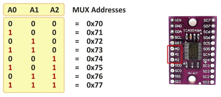
Adres van de chip/module instellen kan met de A0/A1/A2 pins:
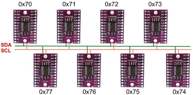
Dit geeft de mogelijkheid om 8×8 = 64 I2C modules aan te sluiten met het zelfde I2C adres:
Arduino
Sluit de module aan volgens onderstaand schema.

Script
Je hebt voor het aansturen van deze chip/module geen speciale bibliotheek nodig, aansturen via de arduino code gaat als volgt:
|
1 2 3 4 5 6 7 8 9 10 11 12 13 14 15 16 17 18 19 20 21 22 23 24 25 26 |
#include <Wire.h> #define TCAADDR 0x70 void tcaselect(uint8_t i) { if (i > 7) return; Wire.beginTransmission(TCAADDR); Wire.write(1 << i); Wire.endTransmission(); } void setup(){ Wire.begin(); } void loop() { tcaselect(0); // Selecteer kanaal 0 // Doe I2C dingen. delay(100); tcaselect(1); // Selecteer kanaal 1 // Doe I2C dingen. delay(1000); } |
Voorbeeld voor het uitlezen van 2 BME280 sensoren:
|
1 2 3 4 5 6 7 8 9 10 11 12 13 14 15 16 17 18 19 20 21 22 23 24 25 26 27 28 29 30 31 32 33 34 35 36 37 38 39 40 41 42 43 44 45 46 |
#include <BME280I2C.h> #include <Wire.h> #define TCAADDR 0x70 #define SERIAL_BAUD 9600 BME280I2C bme; // Default : forced mode, standby time = 1000 ms // Oversampling = pressure ×1, temperature ×1, humidity ×1, filter off, float pres, temp, hum; void tcaselect(uint8_t i) { if (i > 7) return; Wire.beginTransmission(TCAADDR); Wire.write(1 << i); Wire.endTransmission(); } void setup(){ Serial.begin(SERIAL_BAUD); while(!Serial) {} // Wait Wire.begin(); bme.begin(); } void loop() { BME280::TempUnit tempUnit(BME280::TempUnit_Celsius); BME280::PresUnit presUnit(BME280::PresUnit_Pa); tcaselect(0); bme.read(pres, temp, hum, tempUnit, presUnit); Serial.print("\tTemp1: "); Serial.print(temp); Serial.print("C"); Serial.print("\tHum1: "); Serial.print(hum); Serial.print("% RH"); Serial.print("\tPres1: "); Serial.print(pres); Serial.println(" Pa"); delay(100); tcaselect(1); bme.read(pres, temp, hum, tempUnit, presUnit); Serial.print("\tTemp2: "); Serial.print(temp); Serial.print("C"); Serial.print("\tHum2: "); Serial.print(hum); Serial.print("% RH"); Serial.print("\tPres2: "); Serial.print(pres); Serial.println(" Pa"); delay(1000); } |
Console output:
|
1 2 3 4 5 6 7 8 9 10 11 12 13 14 15 16 |
Temp1: 14.31C Hum1: 34.52% RH Pres1: 99211.87 Pa Temp2: 17.60C Hum2: 58.71% RH Pres2: 100469.41 Pa Temp1: 14.31C Hum1: 34.52% RH Pres1: 99215.34 Pa Temp2: 17.60C Hum2: 58.75% RH Pres2: 100472.06 Pa Temp1: 14.32C Hum1: 34.51% RH Pres1: 99216.18 Pa Temp2: 17.61C Hum2: 58.73% RH Pres2: 100480.87 Pa Temp1: 14.31C Hum1: 34.52% RH Pres1: 99217.97 Pa Temp2: 17.61C Hum2: 58.73% RH Pres2: 100476.44 Pa Temp1: 14.31C Hum1: 34.53% RH Pres1: 99207.46 Pa Temp2: 17.61C Hum2: 58.72% RH Pres2: 100476.44 Pa Temp1: 14.32C Hum1: 34.53% RH Pres1: 99214.39 Pa Temp2: 17.61C Hum2: 58.73% RH Pres2: 100476.44 Pa Temp1: 14.32C Hum1: 34.53% RH Pres1: 99211.77 Pa Temp2: 17.61C Hum2: 58.73% RH Pres2: 100479.08 Pa Temp1: 14.32C Hum1: 34.54% RH Pres1: 99217.02 Pa Temp2: 17.62C Hum2: 58.74% RH Pres2: 100474.64 Pa |
Raspberry Pi
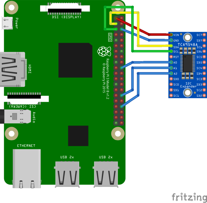
Sluit de module aan volgens onderstaand schema.
| TCA9548A module: | RPI functie: | RPI pin: |
|---|---|---|
| VIN | VCC 3.3V | 1 |
| GND | GND | 6 |
| SDA | SDA | 3 |
| SCL | SCL | 5 |
| A0 | GND | 6 |
| A1 | GND | 6 |
| A2 | GND | 6 |
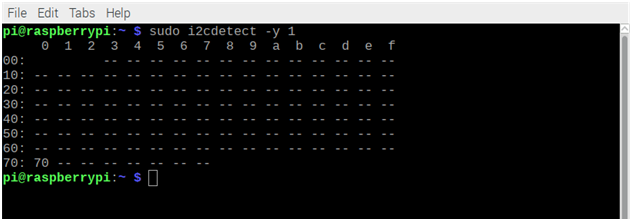
Standaard heeft deze module I2C adres 0x70:
Script
Onderstaand script schakelt naar I2C kanaal 3
|
1 2 3 4 5 6 7 8 9 10 11 12 13 14 15 16 17 18 19 20 21 22 23 24 25 26 27 28 29 30 31 32 33 34 35 36 37 38 39 |
#!/usr/bin/python # TCA9548A I2C multiplexer # I2C Address: 70 through 77 # Channel: 0 - 7 import smbus # class for the I2C switch class I2C_SW(object): # init def __init__(self,name,address,bus_nr): self.name=name self.address=address self.bus_nr=bus_nr self.bus=smbus.SMBus(bus_nr) # Change to i2c channel 0..7 def chn(self,channel): self.bus.write_byte(self.address,2**channel) # block all channels read only the main I2c (on which is the address SW) def _rst(self): self.bus.write_byte(self.address,0) print self.name,' ','Switch reset' # read all 8 channels def _all(self): self.bus.write_byte(self.address,0Xff) print self.name,' ','Switch read all lines' # define the usual sensor 0X70 bus 1 SW=I2C_SW('I2C switch 0',0X70, 1) # SW._all() # SW._rst() # Selecteer kanaal nummer (0-7) # controleer met i2cdetect y -1 (if bus_nr=1) SW.chn(3) |
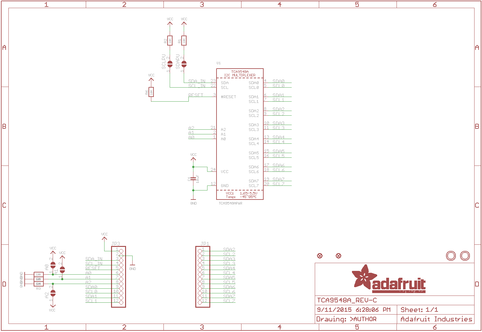
Schema
Teardown
GEEN GEGEVENS
Datasheet
Fritzing

- TCA9548A I2C multiplexer.fzpz 16,34 kb
Downloads
GEEN GEGEVENS