Pinout – Wii Nunchuk

Informatie (ENG)
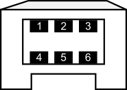
Voor de orginele Nunchuk, is dit de layout van de kleuren van de connector
- Green → SDA
- nc
- Red → 3v3
- White → GND
- nc
- Yellow → SCL
Voor de clone/immitatie Nunchuk is dit de layout van de kleuren van de connector
- Yellow → SDA
- Black → nc
- Green → 3v3
- Red → GND
- nc
- White → SCL
Maar ga nooit blindelings ergens vanuit, meten is weten!
I2C Protocol (eng)
The last section here discusses the actual I2C protocol. If you just want to use the controller, this information is not needed, but if you want to understand the protocol, I hope I can save you some time.
I began developing by scanning for the actual address of the Nunchuk with my I2C scanner, which is 0x52. Reading parameters off of the Nunchuk’s memory via the I2C bus is quite similar to the communication with a normal I2C EEPROM. Before the data from the Nunchuk can be read, it’s necessary to send an initialization sequence.
In order to read data from the Nunchuk, it’s necessary to send the address to read from, since the controller of the Nunchuk increments the address with every read. The data we’re actually interested in lies at address 0x00 and is 6 bytes long. At address 0x20 and 0x30 (seems to be an exact copy of the bytes at 0x20), 16 bytes of calibration data is stored. At address 0xFA you can find the ident number of the device, which is 0xA4200000 for Nunchuck, 0xA4200101 for Classic Controller, 0xA4200402 for Balance and so on.
When data needs to be written to the Nunchuk the format is analogous to the read command. The first byte is the address, followed by the actual data.
Let’s walk through the actual byte sequences of the Nunchuk for the described features:
1. Initialize the Nunchuk:
START, 0x40, 0x00, STOP
This sequence is the normal initialization sequence, which sets the encryption algorithm to default. Every byte which is read from the Nunchuk must then be decrypted with (x ^ 0x17) + 0x17. A better way is disabling encryption with this sequence:
2. Initialize the Nunchuk without encryption:
START, 0xF0, 0x55, STOP
START, 0xFB, 0x00, STOP
This has the benefit that the actual data can be used without the decryption formula and it will work with Nunchuk-clones as well.
3. Read the device ident from extension register:
START, 0xFA, STOP
READ 6 byte
The data is the ident, which I already mentioned, if the connected device is a Nunchuk or Classic controller and so on.
4. Read measurements from the device:
START, 0x00, STOP
READ 6 byte
What you get in return is described in this overview:
| Bit | ||||||||
|---|---|---|---|---|---|---|---|---|
| Byte | 7 | 6 | 5 | 4 | 3 | 2 | 1 | 0 |
| 1 | Joystick X-Axis [7:0] | |||||||
| 2 | Joystick Y-Axis [7:0] | |||||||
| 3 | Accelerometer X-Axis [9:2] | |||||||
| 4 | Accelerometer Y-Axis [9:2] | |||||||
| 5 | Accelerometer Z-Axis [9:2] | |||||||
| 6 | Az [1:0] | Ay [1:0] | Ax [1:0] | ¬Bc | ¬Bz | |||
So, the button values are inverted, and the LSB bits of the accelerometer are contained in byte 6. In the library, I combine the LSB bits with the rest. I’ve seen people using the values without the LSB bits, which is a too simplificated way of getting the signal more stable. To me, I prefer a noisy signal from an ADC, which can be easily filtered with a Complementary or a Kalman Filter instead of cutting off the numbers by rounding – where you lose lots of information.
5. Read actual calibration data from the device:
START, 0x20, STOP
READ 16byte
What you get in return is described in this overview:
| Byte | Description |
|---|---|
| 1 | 0G value of X-axis [9:2] |
| 2 | 0G value of Y-axis [9:2] |
| 3 | 0G value of Z-axis [9:2] |
| 4 | LSB of Zero value of X,Y,Z axes |
| 5 | 1G value of X-axis [9:2] |
| 6 | 1G value of Y-axis [9:2] |
| 7 | 1G value of Z-axis [9:2] |
| 8 | LSB of 1G value of X,Y,Z axes |
| 9 | Joystick X-axis maximum |
| 10 | Joystick X-axis minimum |
| 11 | Joystick X-axis center |
| 12 | Joystick Y-axis maximum |
| 13 | Joystick Y-axis minimum |
| 14 | Joystick Y-axis center |
| 15 | Checksum |
| 16 | Checksum |
Byte 0-3 store the zero values of the X, Y and Z axis, whereas bytes 4-7 store the values at 1G (earth gravitation). The calibration data isn’t used yet in the software implementation.