Ontwerpen – What is a Bypass Capacitor?
Bron: Learning about electronics
A bypass capacitor is a capacitor that shorts AC signals to ground, so that any AC noise that may be present on a DC signal is removed, producing a much cleaner and pure DC signal.
A bypass capacitor essentially bypasses AC noise that may be on a DC signal, filtering out the AC, so that a clean, pure DC signal goes through without any AC ripple.
For example, you may want a pure DC signal from a power source.
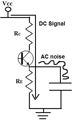
Below is a transistor circuit. A transistor is an active device, so in order to work, it needs DC power. This power source is VCC. In this case, VCC equals 15 volts.
This 15 volts provides power to the transistor so that the transistor can amplify signals. We want this signal to be as purely DC as possible. Although we obtain our DC voltage, VCC, from a DC power source such as a power supply, the voltage isn’t always purely DC. In fact, many times the voltage is very noisy and contains a lot of AC ripple on it, especially at the 60Hz frequency because this is the frequency at which AC signals run in many countries.
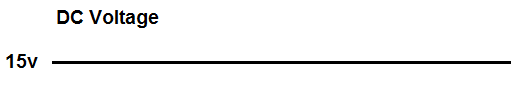
So although we want a pure DC signal, such as below:
Many times, we get a noisy signal that looks like:
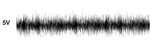
A DC signal such as this is actually very common. This is undesired because it adds noise to the transistor circuit. Therefore, this noisy DC signal will be imposed on the AC signal. So the AC signal which may have music or some type of recording will now have much more noise.
This noise which is on the signal is AC ripple. Many times when using a DC power supply connected to an AC power outlet, it will have some of the AC noise transfer to the DC power voltage. AC ripple can also appear from other sources, so even batteries can produce noise.
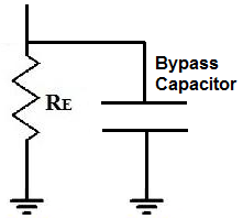
To eliminate this AC ripple, we use a bypass capacitor. So our transistor circuit above will have a bypass capacitor added to it:
A capacitor is a device that offers a tremendously high resistance for signals of low frequencies. Therefore, signals at low frequencies will not go through them. This is because signals (current) always takes the path of least resistance. Therefore, they will instead go through the resistor, RE. Remember, again, this is for low frequency signals, which is basically DC signals.
However, capacitors offer much less resistance at higher frequencies (AC signals). So AC signals will go through the capacitor and then to gorund. Therefore, DC signals will go through the resistor, RE, while AC signals will go through the capacitor, getting shunted to ground. So AC signals get shunted to ground. This is how we have a clean DC signal across our circuit, while AC noise imposed on it is bypassed to ground.
So a bypass capacitor blocks the DC from entering it by the great resistance it offers to the signal but accepts the AC noise that may be on the DC line and shunts or bypasses it to ground. This is how bypass capacitors work.
How to Choose the Value of the Bypass Capacitor
Now that you know conceptually what a bypass capacitor is, the next step is to know how to select the value of the bypass capacitor.
And selecting the value is pretty straightforward.
The value of the bypass capacitor should be at least 1/10th of the resistance across the emitter resistance, RE at the lowest frequency intended to be bypassed.
Because capacitors are reactive devices, they have different resistances to signals based on the signal’s frequency. This is referred to as the capacitor’s reactance, which can be seen as the resistance it offers. We want the capacitor to have 1/10th of the resistance to the flow of current than what the resistor offers for the frequency signal that we want to bypass.
If you visualize the current moving through the transistor, it can take one of 2 paths once it passes the collector and moves through the emitter. Current can either go the resistor, RE or current can flow through the bypass capacitor. Current always takes the path of least resistance. Therefore, current will take the path of the lower resistance. This is why you want the value of the resistance of the bypass capacitor to be at least 1/10th the value of the emitter resistor or, even better, less than one-tenth. We want the AC current to flow through the least resistance path, which is the bypass capacitor if the correct value is chosen.
However, DC signals do not see it as AC. To DC, the capacitor has infinite resistance. So DC will automatically go through the RE resistor, which offers lower resistance by far to the infinite resistance of the capacitor.
AC, however, does not see infinite resistance for the capacitor. If we choose the value correctly for the capacitor, we can make the capacitor a much lower-resistance path to ground, thus shorting out the AC signal to ground.
So let’s go over a practical example of how we would select the bypass capacitor value.
Let’s say we want to bypass the lowest possible frequency of 50Hz, because the frequency of AC voltages worldwide are 50-60Hz. Therefore, this frequency can be a very problematic because often there is AC ripple at this frequency.
Remember, when we said we bias the value of the bypass capacitor based on the lowest frequency that we want to bypass. So by selecting the frequency of 50Hz, this blocks frequencies from 50Hz and higher; so it covers 60Hz. As frequency of an AC signal increases, the resistance of the capacitor decreases and decreases with each increase. Therefore, all the frequencies above the frequency value that we choose get bypassed easier and easier. We’ll demonstrate this all mathematically.
So we decided we want to bypass AC signals 50Hz or higher to ground.
The typical value of an emitter resistor is 400-500Ω. The resistance is kept low so that gain on the transistor isn’t lowered too much.
So let’s say we choose an emitter resistor of 470Ω.
This means that we want the reactance of the capacitor to be one-tenth of 470Ω or less, which is 47Ω or lower. So this is our target.
The formula for the reactance of a capacitor is, XC= 1/2πfc= 1/2(3.14)(50Hz)(C)=47Ω. Solving for the capacitance, C, we get the value of approximately 67μF. So we need a capacitor of at least 67μF to get a resistance of one-tenth the value of 470Ω resistor.
Since a 67μF capacitor isn’t readily available, we can round up to 100μF, which is readily available and easy to obtain. This is even better, because with a larger capacitance, the capacitor offers even less resistance to the AC signal. If we plug a 100μF capacitor into the same capacitor reactance formula, we get XC= 1/2πfc= 1/2(3.14)(50Hz)(100μF)=31.8Ω. This is much lower than 1/10 of the 470Ω resistor that we have in parallel. So it will act effectively to short all AC signals 50Hz or higher to ground to clean up the DC signal.
Even if you wanted, you could increase the capacitance even more to allow for less AC noise on the signal. But a lot of times, this will not be done for cost and size constraints reasons. The larger the size a capacitor is, the more it costs per unit. Also the larger the size of a capacitor, the larger physically is. Therefore, if a company is designing a product, the size of the capacitor could be a problem if there are size constraint issues. The way things are going in electronics, companies want products to be as small and concise as possible. So due to reasons such as these, larger value capacitors won’t always be chosen, but theoretically, they would increase the purity of the DC signal, by allowing more AC to ground.
So again, this is a summary of what a bypass capacitor is and how to select the value of them based on the lowest AC signal desired to be filtered out and the value of the resistance in parallel with the capacitor.
You can check out our bypass capacitor calculator to calculate the value of a bypass capacitor based on the input AC signal frequency and the value of the resistor in parallel.