Prusa i2 “Mendel” onderdeel – Diverse onderdelen
Diverse onderdelen
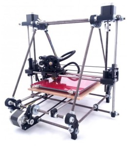
Prusa i2 “Mendel”
De pagina bevat diverse, vervangende of verbeterde onderdelen die ik gevonden heb op internet voor de Prusa Mendel i2.
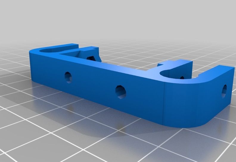
Prusa Mendel i2 modified x-axis endstop holder
Thingiverse commentaar:
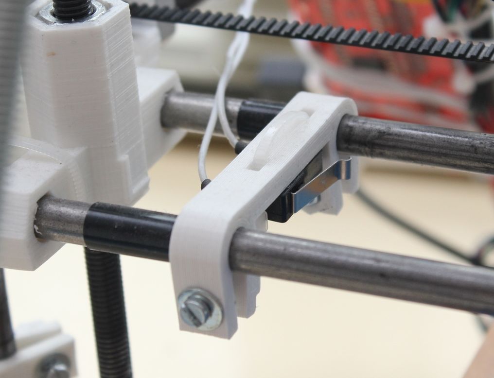
This x-axis endstop holder is a modification of the original Prusa Mendel i2 endstop holder. This modification was made after the head of my printer did not stop because the x-axis endstop switch was somewhat rotated. This version rests on both the x-axis rods. It was created at the end of 2012.
Additional materials:
- 2x M3 bolt
- 2x M3 nut
- 2x M3 washer
- tape (around the rods)
- 1x switch
- 1x zip tie (for the switch)
- glue (for the switch)
Improved X ends for Prusa with clamped rods
Thingiverse commentaar:
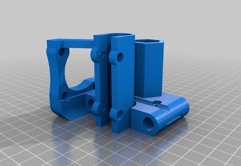
I liked the idea of older Prusa x ends, that use two screws for each rod to fix it, but the implementation was rather weak. With iteration 2’s solution (press fit, closed ends) it’s a mess to disassemble the x axis, so I thought up a new robust version and since modifying one of the existing files would have taken even more time, I designed it from sratch and added even more upgrades like my clamped LM8UU holders!
Prusa’s snap in LM8UU holders have one huge problem: motor- and idler-mount are supported via those holders, so the whole holder can twist unevenly and warp the bearings agains each other. This is avoided with my design.
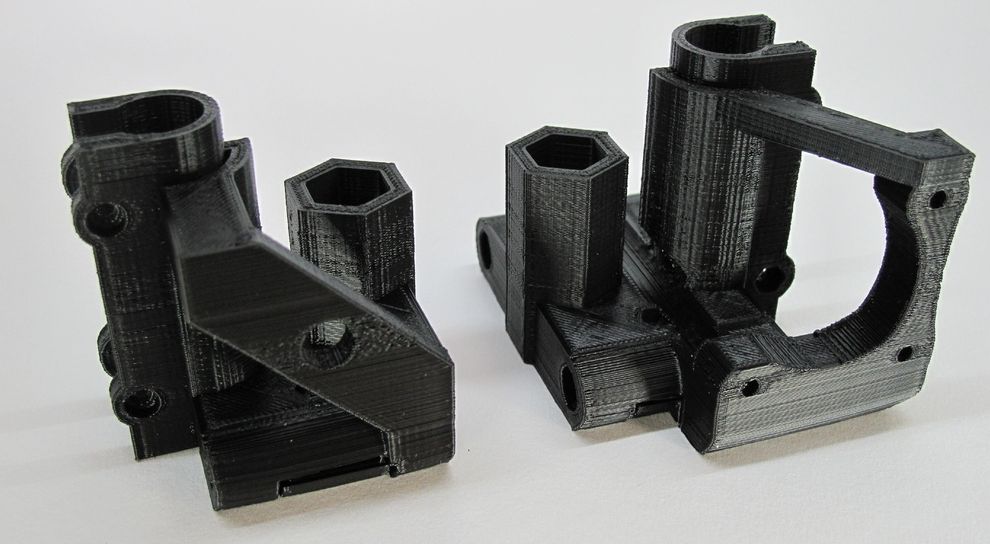
The rods are fixed using one screw for each, tightening the built in clamps. Their screw heads are easily accessible from below and there are nut traps at the top. I made open end rod holes, to be able to push the rods all through. The system achieves a rock solid fit AND easy adjustability – what else you should need?
The leadscrew nut trap uses two bridges inside instead of a circular hole, so there’s no “post-print-processing” (i.e. drilling) necessary in this point.
The design is entirely parametric, so you can even use professional leadscrews like trapezoidal ones with bigger nuts. I additionally attached STLs for use with metric trapezoidal leadscrews TR8x1.5 and nuts of 17mm wrench size (15mm height). For standard Prusa requirements use the “threaded rod” files.
There are thin support layers inside the M3 rod clamp holes that need to be drilled through after printing!
The STLs are generated for 0.25mm layer height – change the parameter in OpenSCAD for your needs.
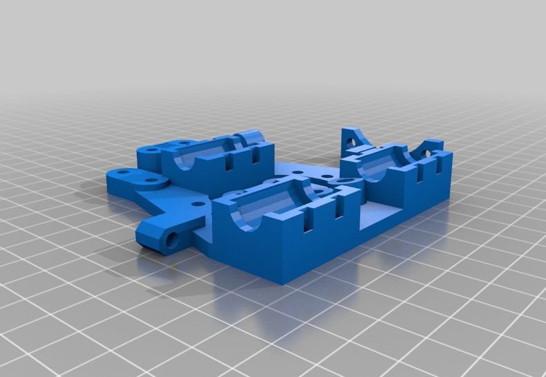
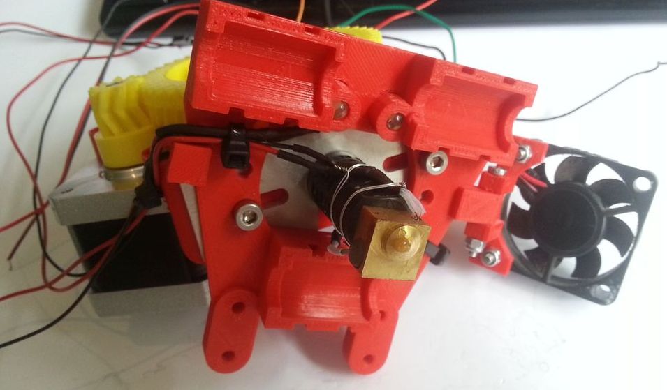
Prusa X carriage, LM8UU with LEDs and fan
Thingiverse commentaar:
This X carriage starts with the LM8UU holders I designed to be very simple and adds a fan bracket that tilts and also a pair of 5mm LED holders.
The fan bracket is optional and can go on either side (or both if you want to go nuts on that). The LED size can be varied in the SCAD as well.
The STL file is set up for SAE 6-32 screws but the SCAD can easily be changed for other sized hardware.
(Note that the belt attachment point on the photo of the bottom of the carriage is incorrect, it was from my first print where I screwed up the direction of the belt)
LEDs:
Insert two 5mm LEDs (you probably want white). Solder together the long lead from one to the short lead from the other (putting them in series), then solder a 220 ohm resistor in series with one of the unused leads on one of the LEDs (it doesn’t matter which). Solder wires leading to 12 volt power to the remaining lead of the resistor and the lead from the other LED. If the LEDs do not light, reverse + and – on the power. If they still don’t light, you probably hooked up one of the LEDs backwards – reverse one of them and try again.
Bearings:
Press the LM8UU bearings in firmly. Insert a small zip tie into each retaining channel, then tighten and snip off the tail.
Installation:
Install as you would any X carriage. It is designed to have the belt come off the bottom of the pulley and bearing and lay on the top surface with the belt teeth up. On one side, use one of the toothed belt clamps and a pair of screws to fasten the belt. On the other side, use the belt tightener with the channel facing down towards the belt, insert a screw and a nut through the tightener and into the belt ram. Wrap the belt over the ram and over the top of the tightener (engaging the belt teeth on top of the tighener) and top it all off with the smooth cap. Tighten everything up and tension the belt as desired.
Aanpassingen nodig
[ADJUSTMENTS FOR LM8UU]
24mm width is to narrow, could not fit the LM8UU bearings (otherwise pliers needed!)
So, edit the file: LM8UU_holder_ziptie.scad and adjust:
LM8UU_length = 24; -TO- LM8UU_length = 24.4;
Now they fit nicely!
[ADJUSTMENT FOR GREG’S WADE EXTRUDER V3]
Also…Greg’s wade extruder v3 is M4 and NOT M3!, i miss the option to seperate the WADE holes from the GT2 belt holes…, so i’ve added this option:
edit the file: x-carriage-ziptie.scad, add line:
screw_thread_diameter_wade = 4.5; -AFTER- screw_thread_diameter = 3.5;
in the function “module groovemount_holes()”, change line:
cylinder(r=screw_thread_diameter/2, h=base_z+groovemount_elevation, $fn=20); -TO-
cylinder(r=screw_thread_diameter_wade/2, h=base_z+groovemount_elevation, $fn=20);