Prusa i3 Rework – Bouwinstructies
3D Printer
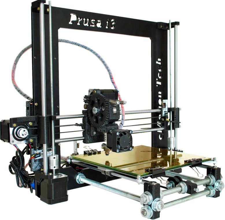
Prusa i3 Rework
Bouwinstructies
Informatie (ENG):
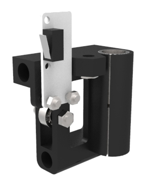
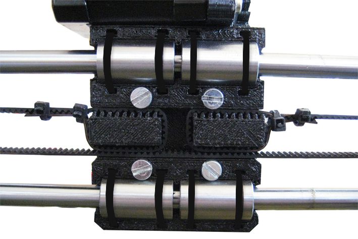
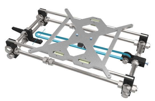
Y axis assembly
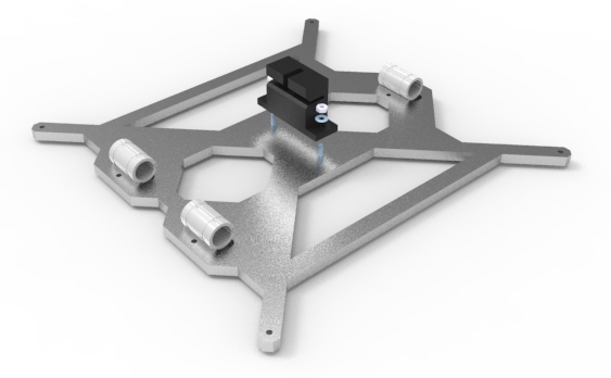
Heated bed mount
Needed parts :
- Heated bed mount
- Y Belt Holder
- 3x Linear bearing LM8UU
- 2x M3x14 mm screw
- 2x Ø3 mm washer
- 2x M3 nut
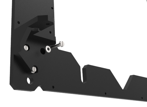
Mount the Y Belt Holder with two M3x14 mm screws (since the aluminum is 6mm thick and the Y Belt Holder is 4mm thick the screws are too long by 4mm since you must NOT have the screws coming out of the other side (the heated bed side) and this means you will have to trim the two screws down by 4mm), two Ø3 mm washers and two M3 nuts. Y Belt Holder orientation doesn’t matter.
Place three LM8UU linear bearings into their respective slots and attach them in place with three zip-ties.
Transverse parts
Needed parts :
- 4x Y Corner
- Y Idler
- Y Motor
- 1x Ball bearing 608
- 4x Threaded rod M10x210 mm
- 22x M10 nut
- 22x Ø10 mm washer
- 1x M8x30 mm screw
- 1x M8 nut
- 2x Ø8 mm wahser
- 1x M4x20 mm screw
- 1x M4 nut
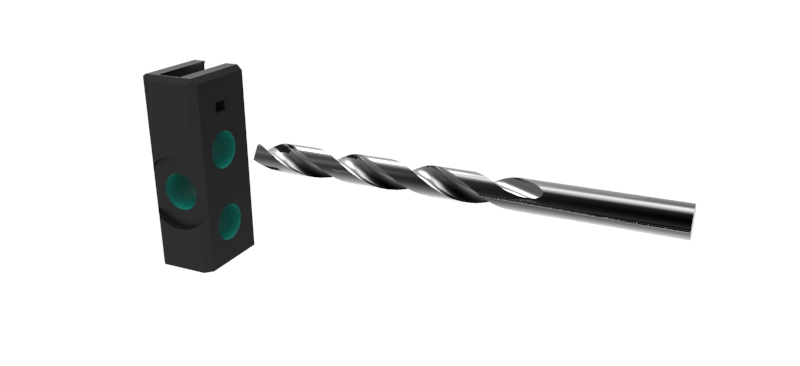
Step 1
Drill with a 10 mm drill the four Y Corner holes (displayed in green). Set counterclockwise rotation and drill progressively and carefully along the axis.
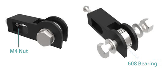
Step 2
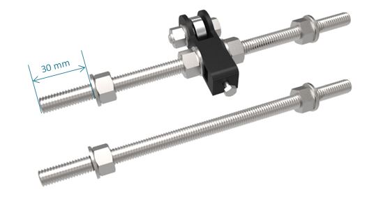
Y Idler assembly: place a M4 nut inside and put a M4x20 mm screw. In case of difficulty, slightly heat the nut using a lighter or a blowtorch and place it with a clamp. Insert a 608 ball bearing into the groove and slide and M8x30 mm screw with two Ø8 mm washers and a M8 nut. You may have to force the screw into the part. Tighten slightly.
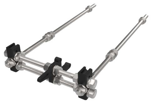
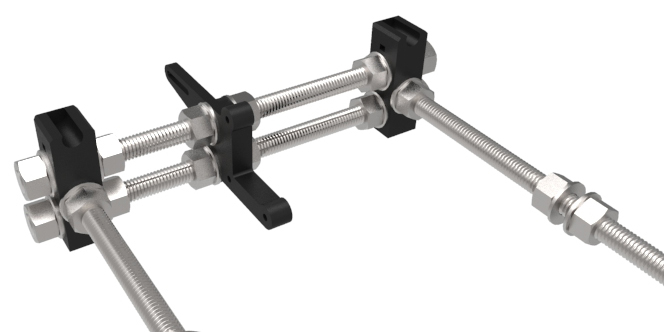
Step 3
Slide the Y Idler assembly in the middle of a threaded rod M10x210 mm and between two Ø10 mm washers and two M10 nuts. Do not tighten the nuts. Thread a M10 nut and washer about 30 mm on both ends. Do the same with a threaded rod M10x210 mm.
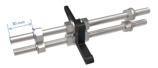
Step 4
Slide two threaded rods M10x210 mm on the Y Motor and fix it with four M10 nuts and four Ø10 washers. Do not tighten the nuts. Thread a M10 nut and washer about 30 mm on both ends.
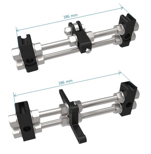
Step 5
Take two Y Corners, the Y Idler assembly and the threaded rod M10x210 mm and fix them with four Ø10 washers and four M10 nuts. Do the same with the Y Motor assembly with two Y Corners. In both cases, adjust the distance between two Y corners (186 mm). Slightly tighten the nuts.
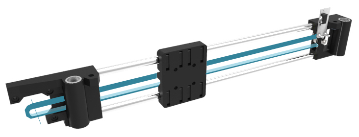
Assembly with the longitudinal parts
Needed parts :
- Heated bed mount assembly
- Transverse parts
- 2x Smooth rod Ø8×350 mm
- 2x Threaded rod M10x380 mm
- 12x M10 nut
- 12x Ø10 mm washer
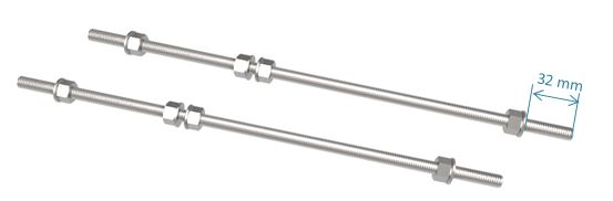
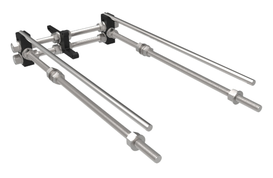
Step 1
Take two threaded rods M10x380 mm, slide on two Ø10 mm washers and thread two M10 nuts into the middle of each rod. Thread a M10 nut and washer about 30 mm on both ends of each rod.
Step 2
Insert the rods into one of the transverse assemblies. Ensure the open end of slots on the top of the Y Corners face down the length of the rods.
Fix each rod using a Ø10 mm washer and an M10 nut. Do not tighten the nuts yet.
Step 3
Insert a smooth rod Ø8×350 mm into each Y Corner top, slide the rod all the way the end of the slot.
With the bearings facing downwards, carefully guide the smooth rods through the bearings on the heated bed mount assembly. Slide the heated bed assembly onto the smooth rods.
Step 4
Insert the other transverse side onto the Ø8 smooth rods and M10 threaded rods. Fix with two M10 nuts and two Ø10 mm washers. Fasten the smooth rods to each Y Corner with four zip-ties.
Using a wrench, tighten the entire assembly with care. Make sure that all four Y Corners touch the ground. Do not tighten the Y Motor and Y Idler nuts.
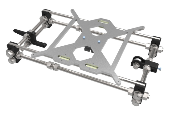
To finish, make sure that the Y-axis moves smoothly. If not, check that the distance between the lateral faces of the Y Corners is 186 mm.
X axis assembly
X End Idler & X End Motor assembly
Needed parts :
- X End Idler
- X End Motor
- 1x 624 ball bearing
- 4x LM8UU linear bearing
- 1x Endstop
- 2x M5 nut
- 1x M4x20 mm screw
- 1x M4 nut
- 2x M3x14 mm screw
- 2x M3 nut
Please take note that Step 1 is if you are using the vanilla Prusa I3 and is not required if you use the RP designed for the Reworked version found at https://www.thingiverse.com/thing:119616
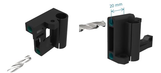
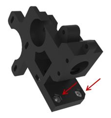
Step 1
Drill with an 8 mm drill X End Idler and X End Motor holes (displayed in green). Do not drill deeper than 20 mm on the X End Motor. Set counterclockwise rotation and drill progressively and carefully along the axis.
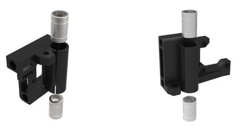
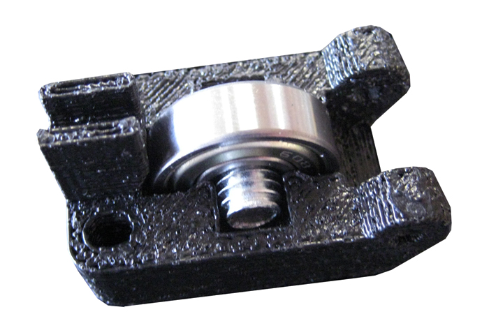
Step 2
Push two LM8UU linear bearings in the X End Idler and two LM8UU linear bearings in the X End Motor. They can be pushed with hands but you can use a rubber mallet carefully if necessary.
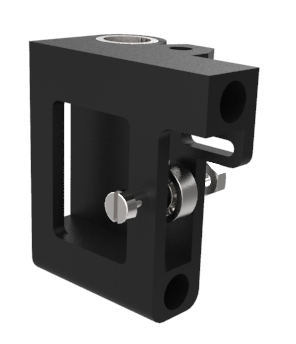
Step 3
Insert an 624 ball bearing (the smallest) between the X End Idler and slide an M4x20 mm screw.
You may have to force the screw into the part but on the Rework’s RP (link above) simply screw the M4 into both sides but do not force it. Fix them with a M4 nut and tighten slightly.
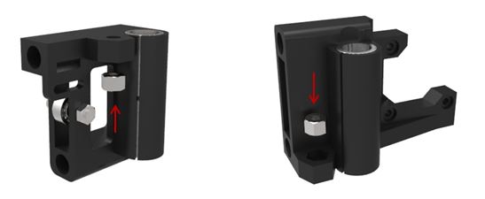
Step 4
Insert two M5 nuts in their marks. In order to do that, thread a threaded rod M5x300mm opposite to the nut. Slightly heat the nut using a lighter or a blowtorch then pull the rod. Be careful with this operation.
Step 5
Affix one endstop with two M3x14 screws and two M3 nuts on the X End Idler.
Note: The SainSmart endstops do not have clearance for the screws due to the placement of the wire harness connector.
One of the following workarounds may work but attempt at own risk.
- Use a flat head screw from the side with the cable wiring harness. Even then 14mm is way too long and 8-10mm would be adequate.
- Reposition the wire harness connector by carefully and slowly bending it outwards just enough to clear the screws; use the wire harness for added leverage.
X Carriage
Needed parts :
- X Carriage
- 4x LM8UU linear bearing
- Zip-ties
Insert four LM8UU linear bearings on the X Carriage and fix them with eight zip-ties. Make sure to put the « head » of the zip-tie on bearings side.
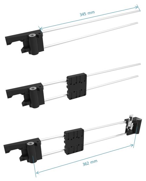
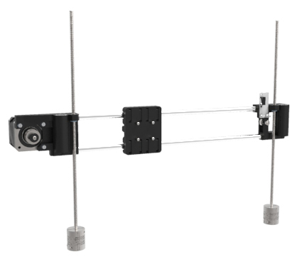
X-Axis assembly
Step 1
Push two smooth rods Ø8×370 mm through the X End Motor. Use a rubber mallet carefully if necessary. The excess length is about 345 mm.
Step 2
Slide the X Carriage assembly carefully through smooth rods.
Step 3
Insert the X End Idler assembly and adjust the distance between both Z-axis (about 362 mm).
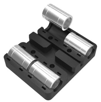
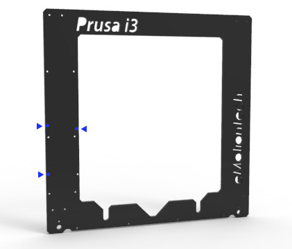
Connecting X-axis and Z-axis
Needed parts :
- Single frame
- X-axis assembly
- Z Axis Top Left
- Z Axis Top Right
- Z Bottom Left
- Z Bottom Right
- 2x Smooth rod Ø8×320 mm
- 10x M3x14 mm screw
- 10x M3 nut
- 10x Ø3 mm washer
Step 1
Fix Z Axis Top Left and Z Axis Top Right on the single frame with four M3x14 mm screws, four Ø3 mm washers and four M3 nuts. Make sure that the nut is at the back of the single frame.
Step 2
Fix Z Axis Bottom Left and Z Axis Bottom Right on the single frame with six M3x14 mm screws, six Ø3 mm washers and 6 M3 nuts. Make sure that the nut is at the back of the single frame.
Step 3
Insert two smooth Ø8×320 mm carefully on both Z Axis Top and slide them by half.
Step 4
Insert the X-axis assembly through smooth rods carefully. Slide the two smooth rods and insert them in both Z Axis Bottom. The two rods do not have to exceed both Z Axis Botoom.
To finish, make sure that the X-axis move smoothly on the Z-axis. Otherwise, verify the distance between both Z-axis (360 mm).
Motor assembly
Z-axis
Needed parts :
- Endstop Z Holder
- 2x Coupling 5×5
- 2x NEMA 17 motor
- 1x Endstop
- 2x Threaded rod M5x300 mm
- 8x M3x14 mm screw
- 2x M3 nut
- 8x Ø3 mm washer
Step 1
Insert a threaded rod M5x300 mm at the half length of a coupling 5*5 and fix it with two grub screws. Do the same for the other rod.
Step 2
Thread each threaded rod in X End Idler and X End Motor M5 nut at half length.
Step 3
Take the single frame assembly and place two NEMA 17 motor with their supply wires against the aluminum frame. There are two ways to route the wires for the motors: you can either use the hole (by removing the connectors, cutting the wires, etc) or use the notches at the bottom of the frame. Gently lifting the plastic tabs on the connectors and sliding the wires out one at a time is tedious, but allows you to avoid cutting the wires in order to route them through the hole.
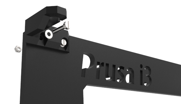
Step 4
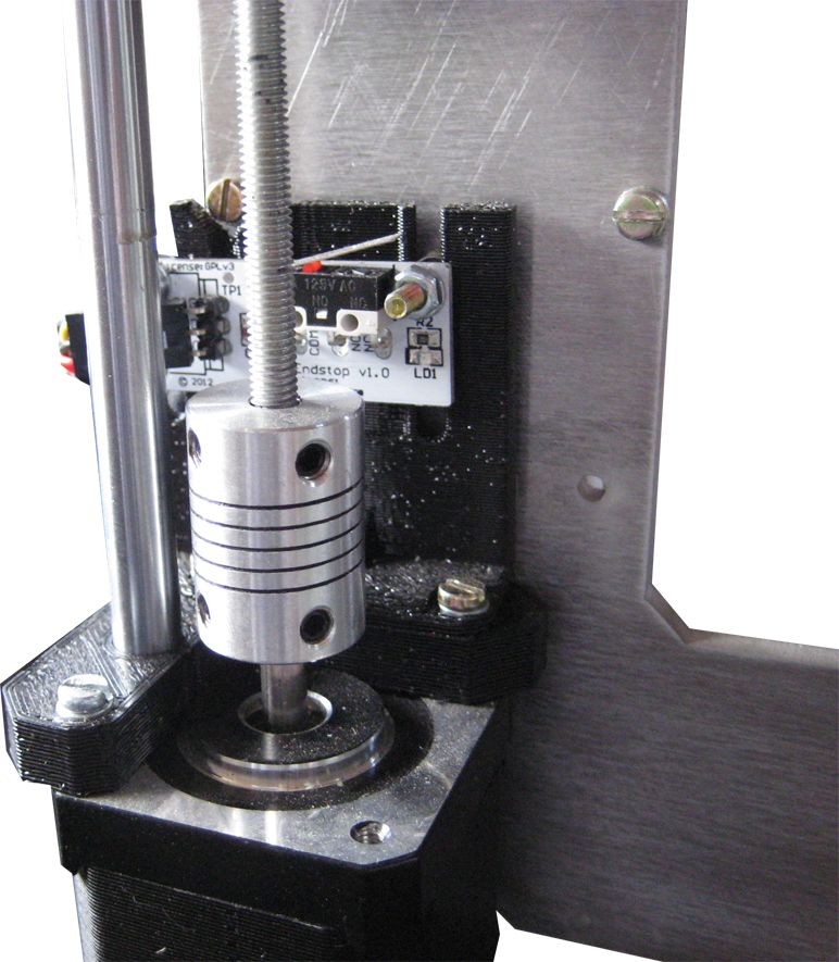
Fix an endstop to the Endstop Z Holder with two M3x14 mm screws (these need to have very thin heads), two Ø3 mm washers (on the rear) and two M3 nuts. Slightly tighten it at half height. The adjustment will be made in the following.
Step 5
Place the Endstop Z assembly on the Z Axis Bottom left and fix it with left motor with three M3x14 mm screws and three Ø3 mm washers.
Fix right motor with three M3x14 mm screws and three Ø3 mm washers. Note: On the Kysan 1124090 stepper motor, M3x14mm is 1.5mm-2mm too long and you will need to cut off 2mm from the screws or shim it with 3x M3 washers per screw.
Step 6
Fix both coupling at both motor shafts with grub screws. Make sure to place a grub screw in the face of the flat of the shaft.
Tighten both grub screws with an Allen wrench.
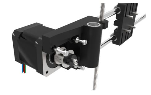
Y-axis
Needed parts :
- 1x NEMA 17 motor
- 1x Endstop
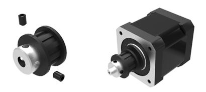
- 1x GT2 pulley
- 5x M3x14 mm screw
- 2x M3 grub screw
- 2x M3 nut
- 5x Ø3 mm washer
Step 1
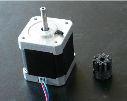
Thread two M3 grub screws on a GT2 pulley. Slide this pulley on the motor shaft and fix it. Make sure to place a grub face to face with the flat of the shaft.
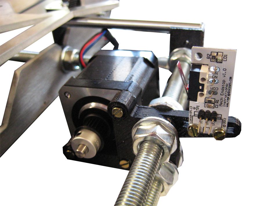
Step 2
Place and fix the previous NEMA 17 motor on the Y Motor with three M3x14 mm screws (on the Kysan 1124090 stepper motor M3x14mm is 1.5mm-2mm too long and you will need to cut off 2mm from the screws) and Ø3 mm washers. Place supply wires down.
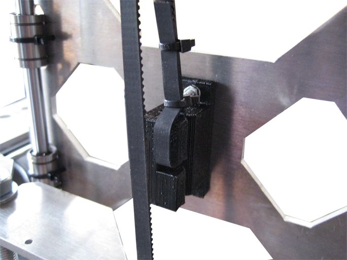
Place and fix an endstop with two M3x14 mm screws and two Ø3 mm washers. The endstop have to be on the bottom of the groove.
Please note that the above step will not work with the SainSmart endstops as the wiring harness on the endstops gives zero room for any nuts or screws to attach the endstop. The only way to fix this is to use a flat head screw from the side with the cable wiring harness. Even then 14mm is way too long and 8-10mm would be adequate.
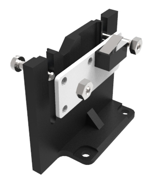
X-axis
Needed parts :
- 1x NEMA 17 motor
- 1x GT2 pulley
- 3x M3x14 mm screw
- 2x M3 grub screw
- 3x Ø3 mm washer
Step 1
Thread two M3 grub screws on the GT2 pulley. Slide this pulley on the motor shaft and fix it. Make sure to place a grub screw face to face with the flat of the shaft.
Step 2
Place and fix the previous NEMA 17 motor on the X End Motor with three M3x14 mm screws (on the Kysan 1124090 stepper motor M3x14mm is 1.5mm-2mm too long and you will need to cut off 2mm from the screws) and Ø3 mm washers. Place supply wires down.
Mechanical frame assembly
Needed parts :
- Y-axis assembly
- Single frame assembly
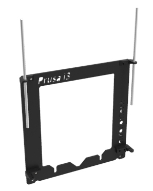
Step 1
Insert the single frame assembly between both M10 nuts and Ø10 mm washers which are on the Y-axis assembly. The Y-axis assembly has to be inserted on both single frame grooves. Moreover, the Y Motor has to be placed nearest you.
Step 2
Adjust the single frame assembly to have 245 mm from the front of the aluminium frame to the external side of an Y Corner. Make sure that this dimension is verified on both left and right sides of the heated bed. This setting allows you to maximize printing workspace.

Step 3
Strongly tighten both couple of M10 nuts and Ø10 mm washers on the single frame assembly. Make sure that the mechanical frame is stable.
X and Y axis motions
X-axis belt
Needed parts :
- GT2 Belt (900 mm)
- Zip-ties
Step 1
Insert one end of the belt on one side of the X Carriage, do a loop and fix it with two zip-ties. The belt should be at the same level as the slot.
Step 2
Insert the belt either to the X End Idler or to the X End Motor depending to how you placed the belt on the previous step.
Do a loop, temporarily tighten the belt and insert it on the last slot of the X Carriage.
Step 3
Tighten the free end of the belt and fix it with two zip-ties.
This step is difficult so please take the time to make a proper tightening.
Y-axis belt
Needed parts :
- GT2 belt (760 mm)
- Zip-ties
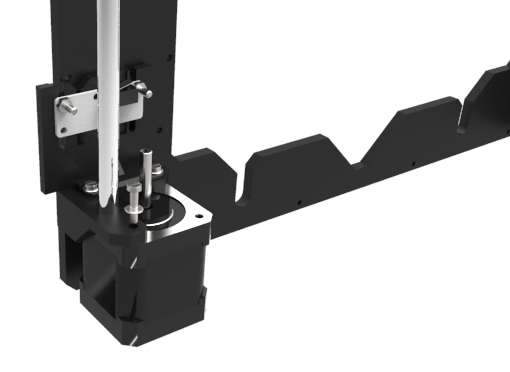
Step 1
Return your machine and align Y Motor pulley, Y Belt holder and Y Idler bearing. The Y Idler assembly should not be fixed.
Step 2
Insert one end of the belt on one side of the Y Belt Holder, do a loop and fix it with two zip-ties.
The belt should be at the same level as the slot.
Step 3
Insert the belt either to the Y Idler or to the Y Motor depending to how you placed the belt on the previous step.
Do a loop, temporarily tighten the belt and insert it on the last slot of the Y Belt Holder.
Step 4
Move your Y-axis near the motor. Adjust Y Motor placement to align the belt properly. This helps to avoid some friction of the belt (I spent 45 minutes trying to make step 4 and step 5 perfect and you just aren’t going to get it perfect so do the best you can to keep the belt from hitting the sides of the GT-2 pulley and/or the Y Idler when you move the plate along the Y-Axis). Make sure that both bolt couples are aligned. Tighten the nuts with hands.
Step 5
Move your Y-axis at the opposite and do the same operation. Repeat the step 4 and 5 until your Y belt is properly aligned.
Step 6
When the belt is aligned, tighten the free end of the belt, and fix it with two zip-ties. Slightly tighten the belt, and cut both ends if necessary.
Step 7
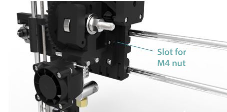
An M4x20 mm screw located on the Y Idler allows you to tighten the belt properly, but be careful because it is not necessary to strongly tighten the belt as it has to be a little loose.
Heated bed assembly
Thermistors assembly
Needed parts :
- 2x Thermistor
- 2x Connecting wire (2 pins)
- Teflon wire (not included)
- Polyimid tape
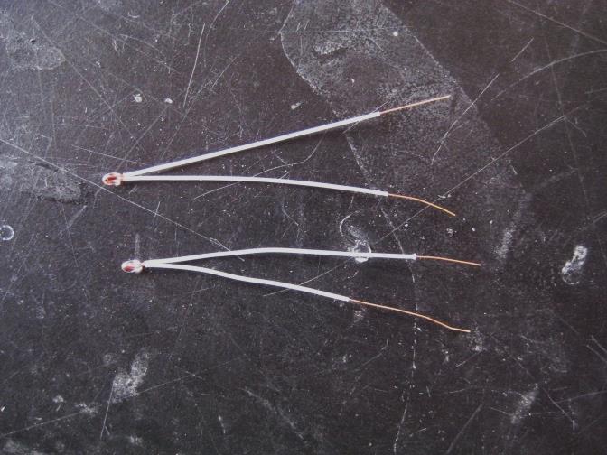
Step 1
Insert two teflon wires at both ends to protect the thermistors. Let the ends free to weld connecting wires (see pictures below).
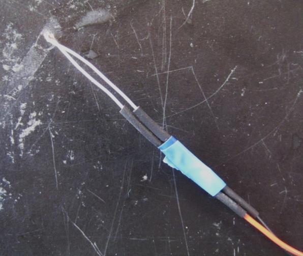
Step 2
Weld two connecting wires to both thermistor ends. Repeat this step for the other thermistor. We strongly recommend you to protect the weld with heat shrink tubing or an insulating adhesive tape.
Heated bed assembly
Needed parts :
- 1x PCB heatbed
- 1x Glass plate
- 1x Thermistor assembly
- 4x Binder clip
- 4x M3x14 mm screw
- 4x M3 nuts
- 16x Ø3 mm washer
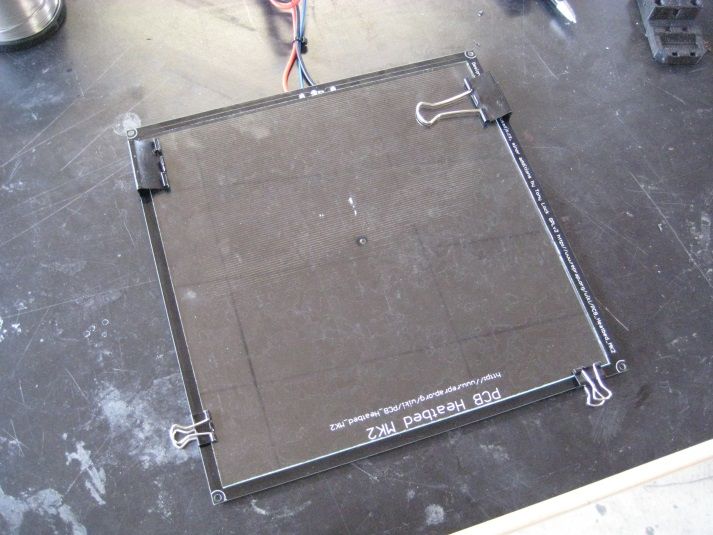
Step 1
Place the glass plate on the top of the PCB heatbed (the face with writing) and fix it with four binder clips.
Step 2
Use high temperature silicone and place a drop in center hole (PCB heatbed bottom side).
Step 3
Place the head of the thermistor in the center hole and make sure that there is a contact with the glass plate. Fix thermistor wires with some Polyimid tape.
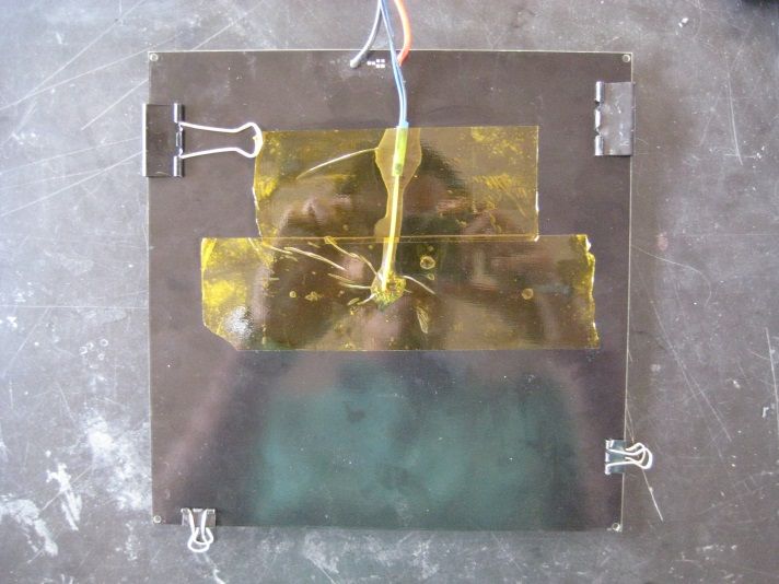
Step 4
Cover the glass plate with Polyimid tape to improve adhesion during future printings. Make sure to remove air bubbles during this step.
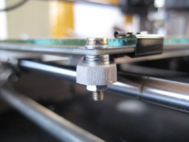
Step 5
Fix the Heated bed assemby on the Heated bed mount (Y-axis) with three Ø3 mm washers between, one Ø3 mm washer on top, an M3x14 mm screw and an M3 nut on each corner.
Extruder assembly
Extruder assembly
Needed parts :
- Wade Extruder Body
- Extruder Idler
- Fan duct
- 3x 608 ball bearing
- 1x Fan 4×4
- 1x Connecting wire (2 pins)
- 1x Hobbed bolt
- 2x Springs
- 1x M8x20 mm grub screw
- 4x Ø8 mm washer
- 1x M8 Nylstop nut
- 4x M4 nut
- 2x M3x60 mm screw
- 3x M3x30 mm screw
- 4x M3x14 mm screw
- x M3 nut
- x Ø3 mm washer
Step 1
Insert two M4 nuts in their marks. To do that, slightly heat the nut using a lighter or a blowtorch then push it in its mark. Be careful with this operation.
Keep the two others nuts for a following step.
Step 2
Slide an M8x20 mm grub screw through a 608 ball bearing then push this assembly inside the Extruder Idler. Use a rubber mallet to seat the grub screw if required.
Step 3
Fix the Extruder Idler to the Wade Body Extruder with an M3x30 mm screw and two M3 nuts – one goes into a slot on the inside. Slightly tighten the nut to allow its rotation.
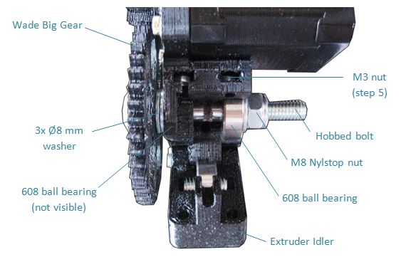
Step 4
Slide the hobbed bolt through the Wade Big Gear. Slide three Ø8 mm washers and a 608 ball bearing onto the hobbed bolt. Insert the bolt into the Wade Extruder Body and locate the bearing into the recess. Slide another 608 ball bearing onto the hobbed bolt and locate in the recess on the other side of the extruder body. Fix the bolt in place using a Ø8 mm washer and a M8 Nylstop nut. Before tightening, make sure that the teeth’s is facing the hole.
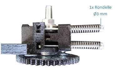
Step 5
Insert two M3 nuts into their slots. Use two M3x60mm screws, each with a Ø3 mm washers (rondelle) and a spring, to hold the Extruder Idler in place.
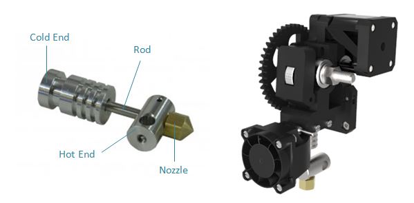
Step 6
Make sure that the Magma Hotend is correctly assembled (tighten the parts: Cold End, rod, Hot End and nozzle). Clean the Wade Extruder Body Ø16 mm hole and insert the Magma Hotend. You have to force and to spin the Hot End (see illustration below). Thread two M3x30 mm screws into the Wade Extruder Body to hold the Cold End in place.
Step 7
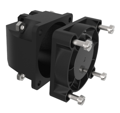
Take an 4×4 fan and cut the supply wire at half length. Solder the additional supply wire (black/black and red/red) and solder the plug again. We recommend you to protect the solder joint with heat shrink tubing or an insulating adhesive tape.
Step 8
Place the fan on the Fan Duct (supply wires down) and make sure that the fan’s air flow is going towards the fan duct then affix the fan to the fan duct with M3x14 mm screws and four M3 nuts.
Connecting to X-axis
Needed parts :
- Extruder assembly
- Fan duct assembly
- Wade Small Gear
- 1x NEMA 17 motor
- 4x M4x20 mm screw
- 1x M3x30 mm screw
- 3x M3x14 mm screw
- 1x M3 grub screw
- 2x M3 nut
- 3x Ø3 mm washer
Step 1
Insert the two previous M4 nuts in their slots and thread M4x20mm screws to maintain the extruder assembly against the X Carriage.
Step 2
Slide the Wade Small Gear on the shaft of a NEMA 17 motor with an M3 griub screw and an M3 nut inserted in his slot. If necessary, drill with hands the Wade Small Gear hole with an Ø5 mm drill. Make sure to place a grub face to face with the flat of the shaft.
Step 3
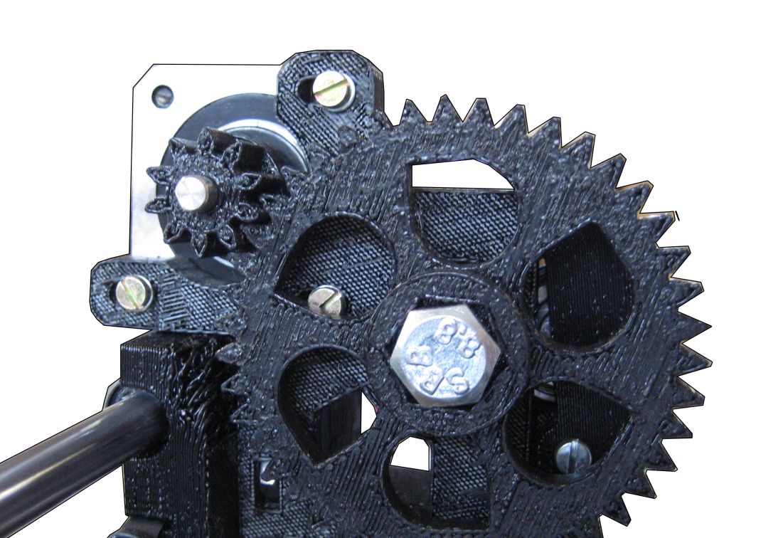
Place the motor assembly against the Wade Extruder Body (supply wires upwards). Insert three M3x14 mm screws and three Ø3 mm washers without tightening. A note about the length of these screws: On my Kysan 1124090 motors 14mm was way too long and I had to cut off 1.5-2mm from the screws for them to go all the way into the motor. Please, be aware of this.
Slide the motor assembly against the Wade Big Gear and thread the screws. Make sure that the backlash is minimum.
Step 4
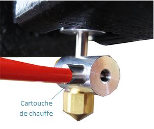
Insert the resistor (cartouche de chauffe) into the Hot End (in the dedicated hole). Supply wires should extend from the right when you are facing your printer.
Step 5
Take the other thermistor assembly, place a drop of high temperature silicone and insert the thermistor head in the little notch of the nozzle. The thermistor head should be against the nozzle.
Note: Make sure that the nozzle can move all along the heated bed. To do that, move the extruder assembly on the x-axis and the heated bed on the y-axis.
Step 6
Fix the Fan Duct assembly on the Wade Extruder Body with an M3x30 mm screw and an M3 nut.
Nozzle height adjustment
Note : This adjustment must be repeated when an extruder component (the Magma Hotend for example) is changed.
Step 1
Move the X-axis to the right. You should hear the endstop “clic” at the end. The nozzle should be near the glass plate edge.
Step 2
Rotate simultaneously both Z-axis coupling counterclockwise to move the nozzle down. Move the nozzle down until to be able to pass a sheet of paper folded in half.
Step 3
Move the X-axis to the extreme left and make sure that the nozzle is at the same height. Otherwise, hold the right coupling and rotate the left coupling to move the nozzle up or down.
Step 4
Once the nozzle height adjustment made, adjust the Z-axis endstop until you hear the « clic ». This position defines Z-axis home.
Electronics and wiring
Mounting electronics
Needed parts
- RAMPS
- Arduino Mega 2650
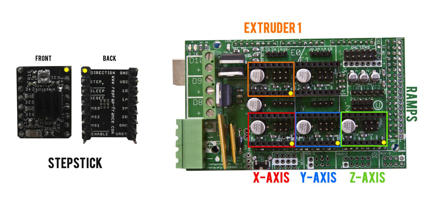
- 4x stepsticks
- 3x Arduino washer
- 3x M3x24 mm screw
- 3x M3 nut
- 3x Ø3 mm washer
Step 1
Mount the RAMPS on the Arduino Mega 2560. You may have to cut the solder joints located below the RAMPS power supply plug. You should have both power supply plugs on the same side.
Step 2
Before plugging in the stepsticks, place three jumpers under where each stepstick goes. This will tell RAMPS to use the highest level of micro-stepping that is supported. Plug each stepstick on the RAMPS according to the illustration below. If you are not using a dual extruder, you will likely have an empty socket. Note also that the stepper coils are numbered 1 and 2, with 1A and 1B going to one coil, and 2A and 2B going to the second coil.
Step 3
Fix the electronics assembly to the rear of the aluminum plate with three Arduino washers used to electrically insulate it. Power supply plugs are oriented UPWARD (original wiki entry here said downward but the hole orientation of the real Prusa I3 will not allow that). Use three M3x24 mm screws, three Ø3 mm washers (on the RAMPS) and three M3 nuts.
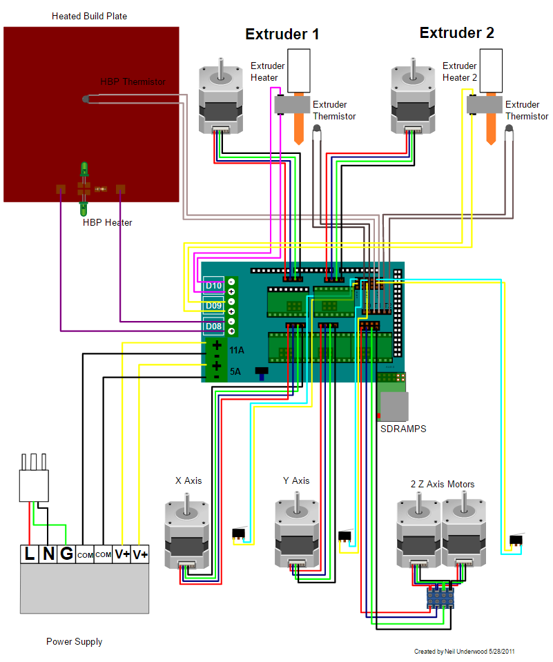
Wiring
All electrical connections are summarized on the following scheme : LIEN PAGE REPRAP
Note : The second extruder may be replace by a fan to cool the print.
Endstop wiring
Plug the three endstops to the RAMPS with three connecting wires (wires with an « Endstop » mark) according to the following wiring scheme. This scheme shows the connection for X, Y, and Z min stops. If you have a Y max stop for instance, then you would need to move the Y connection over one. :

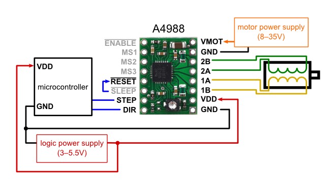
Motors wiring
You have to connect both Z-axis NEMA 17 motors to work in parallel. To do that, weld both power supply wires (cut in a previous step) according to their colors : red/red, green/green, blue/blue and black/black. We strongly recommend you to protect each weld with heat shrink tubing or an insulating adhesive tape. Note: the RAMPS 1.4 allows you to plug in two Z-axis motors, so cutting/welding of the wires might not be needed.
NEMA 17 wires color can change depending on the supplier and there is no risk in case of a wrong wiring. Indeed, the wires are always associated in pairs (one pair for each coil). SO there is no risk if the color of supply wires doesn’t match the wiring diagram.
Hot End resistor and PCB heatbed wiring
The Hot End (or extruder) resistor is not polarized and is plugged to D10.
PCB heatbed is plugged to D08. Make sure to not invert the positive and negative poles.
Thermistors wiring
The thermistor is not polarized. So you can connect the PCB heatbed thermistor and the Extruder thermistor in both ways.
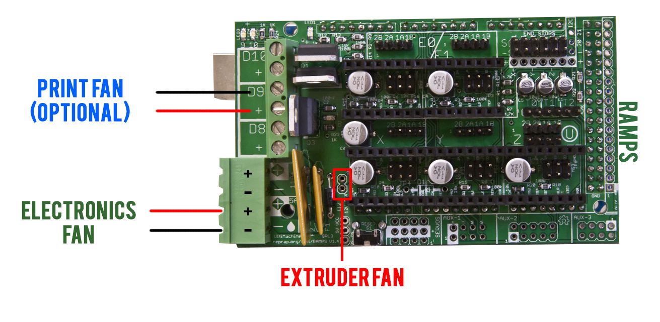
Fans wiring
Plug the extruder fan directly to its dedicated power supply pins (see illustration below).
If you have a fan which cools the electronics then plug it directly to the RAMPS.
If you have a fan which cools the print then plug it to D9.
Power supply wiring
The principle power supply wire is not included. You have to strip an end of a power cable and to connect to the power supply (L, N, G plugs). Make sure to do this operation properly.
The power supply is connected to the RAMPS with additional connecting wires. You have to strip both ends, make sure to follow the scheme correctly.
Check the power supply for 110volt vs 220volt operation.

Overige handleidingen: