Raspberry Pi – CAN Bus communicatie (GPIO)
Het is mogelijk een raspberry pi te gebruiken met een CAN Bus interface, met CAN Bus kan je datalijnen gebruiken tot ca. 5000m, en apparaten werken peer-to-peer (ipv master – slave) dat is erg interessant!
Wat je nodig hebt is een CAN Bus module met een controller en transciever om het differentiële signaal van de CAN Bus bus om te zetten naar SPI signalen voor de Arduino (en andersom).
Hardware CAN Bus controller module
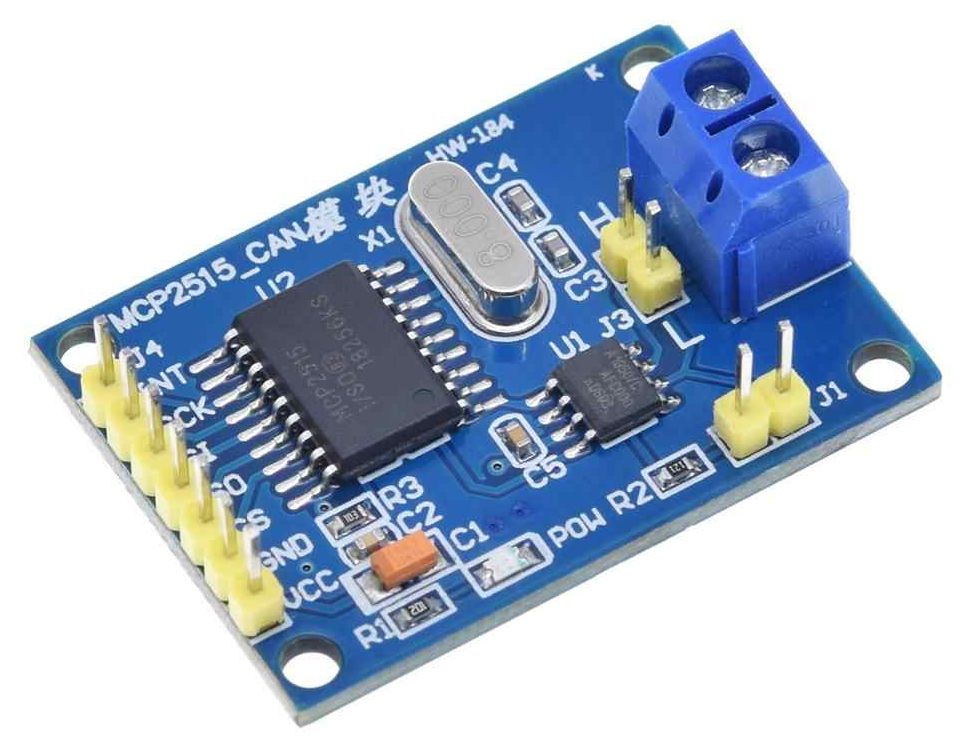
The MCP2515 CAN Bus Controller is a simple Module that supports CAN Protocol version 2.0B and can be used for communication at 1Mbps. In order to setup a complete communication system, you will need two CAN Bus Module.
- Supports CAN V2.0B specification, with communication speed up to 1Mb/s.
- 0 to 8-byte data field with standard frame, extended frame and remote frame.
- 5V DC power supply module, SPI interface protocol control.
- Onboard 120 Ohm termination resistor.
- Working current: 5mA (1 microamp standby current).
- Operating temperature: -40 C – +85 C
This particular module is based on MCP2515 CAN Controller IC and TJA1050 CAN Transceiver IC. The MCP2515 IC is a standalone CAN Controller and has integrated SPI Interface for communication with microcontrollers.
Coming to the TJA1050 IC, it acts as an interface between the MCP2515 CAN Controller IC and the Physical CAN Bus.
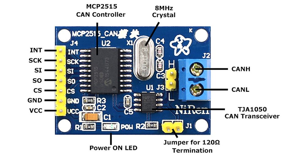
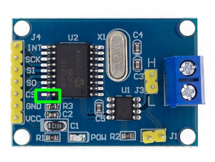
The following image shows the components and pins on a typical MCP2515 Module:
Module schema
Before seeing the schematic of the module, you need to understand a couple of things about both the ICs i.e. MCP2515 and TJA1050.
MCP2515 IC is the main controller that internally consists of three main subcomponents: The CAN Module, the Control Logic and the SPI Block.
CAN Module is responsible for transmitting and receiving messages on the CAN Bus. Control Logic handles the setup and operation of the MCP2515 by interfacing all the blocks. The SPI Block is responsible for the SPI Communication interface.
Coming to the TJA1050 IC, since it acts as an interface between MCP2515 CAN Controller and the physical CAN Bus, this IC is responsible for taking the data from the controller and relaying it on to the bus.
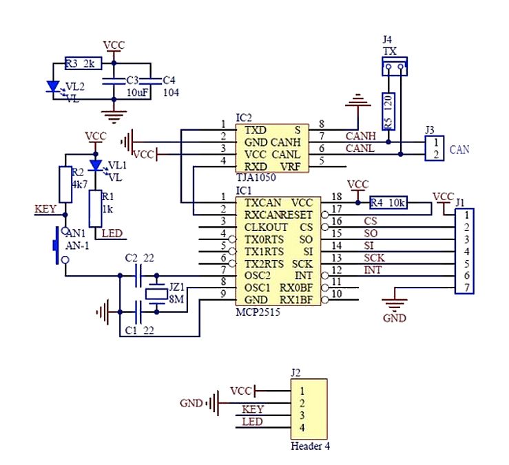
The following image shows the schematic of the MCP2515 CAN Module and it shows how MCP2515 IC and TJA1050 IC are connected on the Module.
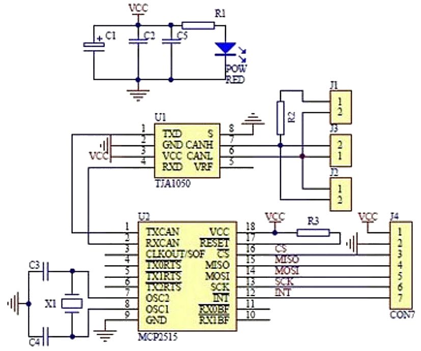
Schema met component waarden:
Before connecting to the Raspberry Pi
While this module is dirt cheap and extremely prevalent, it is not 3.3V compatible and hence Raspberry PI compatible. This board is designed to work from 5V only.
The on-board Microchip MCP2515 CAN Controller supports a wide voltage range from 2.7 to 5.5V. However, the CAN Transceiver, the TJA1050 from NXP only supports 4.75 to 5.25V.
Solution(s) to make this module suitable for the Raspberry Pi 3.3V
- Levelshifter?
Note: You can not use a levelshifter 3.3V <> 5.0V, the MPC2515 will not be recognized for intialisation by the Raspberry Pi !
- MCP2515 CAN Bus Module Board with TJA1050 SN65HVD230
If you are proficient at SMD rework, you can remove the 5V CAN Transceiver and install a 3.3V version. I did this and opted to replace the 5V TJA1050 with the 3.3V SN65HVD230.
- MPC2515 3.3V adjustment
With a pincet, bent this VCC pin (see under) upwards, solder a wire on it and connect to 3.3V on the pi:
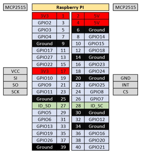
Raspberry Pi connection
Sluit de CAN Bus Module aan zoals hieronder aangegeven (let op pas de 3.3V hack toe).
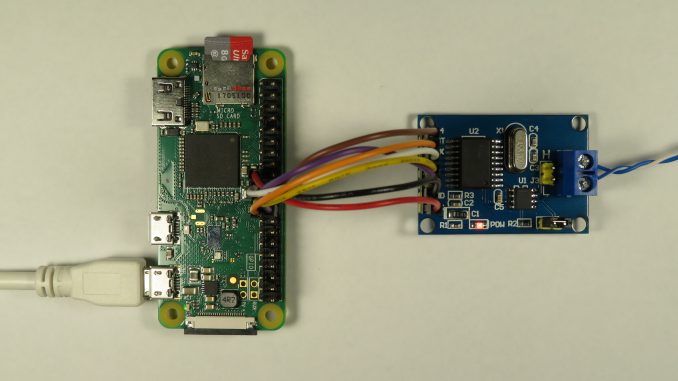
Voorbeeld op de Raspberry pi ZERO:
PICAN 2 HAT
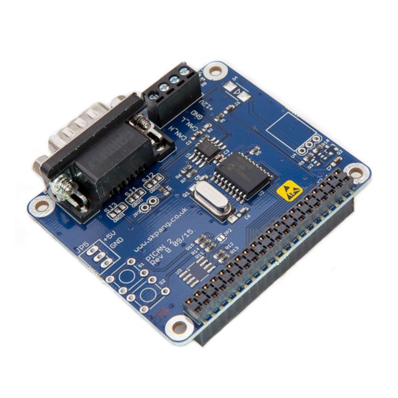
The PiCAN2 board provide CAN-Bus capability for the Raspberry Pi. It uses the Microchip MCP2515 CAN controller with MCP2551 CAN transceiver. Connection are made via DB9 or 3 way screw terminal.
Easy to install SocketCAN driver. Programming can be done in C or Python.
Features
- CAN v2.0B at 1 Mb/s
- High speed SPI Interface (10 MHz)
- Standard and extended data and remote frames
- CAN connection via standard 9-way sub-D connector or screw terminal
- Compatible with OBDII cable
- Solder bridge to set different configuration for DB9 connector
- 120Ω terminator ready
- Serial LCD ready
- LED indicator
- Foot print for two mini push buttons
- Four fixing holes, comply with Pi Hat standard
- SocketCAN driver, appears as can0 to application
- Interrupt RX on GPIO25
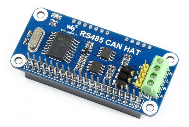
RS485 CAN HAT
Features
- Raspberry Pi connectivity, compatible with Raspberry Pi Zero/Zero W/Zero WH/2B/3B/3B+
- CAN function, onboard CAN controller MCP2515 via SPI interface, onboard transceiver SN65HVD230
- RS485 function, controlled via UART, half-duplex communication, supports automatic TX/RX control without programming, onboard transceiver SP3485
- Onboard TVS (Transient Voltage Suppressor), effectively suppress surge voltage and transient spike voltage in the circuit for RS485 transceiving, lightning-proof & anti-electrostatic
- Reserved control pins, allows to work with other control boards
- Comes with development resources and manual (examples in wiringPi/python)
Specifications
- Operating voltage: 3.3V
- CAN controller: MCP2515
- CAN transceiver: SN65HVD230
- 485 transceiver: SP3485
- Dimension: 65mm x 30mm
- Mounting hole size: 3.0mm
| PIN | Raspberry Pi (BCM) | DESCRIPTION |
|---|---|---|
| 3V3 | 3V3 | 3.3V Power |
| GND | GND | Ground |
| SCK | P11 / SCLK | SPI clock input |
| MOSI | P10 / MOSI | SPI data input |
| MISO | P9 / MISO | SPI data output |
| CS | P8 / CE0 | SPI chip selection |
| INT | P25 | Interrupt |
| RXD | P15 / RXD | RS485 UART receive |
| TXD | P14 / TXD | RS485 UART transmit |
| RSE | P4 | RS485 TX/RX control (auto control by default, some soldering is required to enable manual control), high for TX, low for RX |
Configure CAN Bus on the Raspberry Pi
CANBUS MODULE
/boot/config.txt
Without an ID EEPROM on the ‘hat’ specifying the hardware, the Linux kernel will not automatically discover the CAN Controller on the SPI interface. To load the appropriate driver, you must specify device tree overlay settings at boot.
Add the following line(s) to your /boot/config.txt file:
|
1 2 3 |
dtparam=spi=on dtoverlay=mcp2515-can0,oscillator=8000000,interrupt=25,spimaxfrequency=500000 dtoverlay=spi-bcm2835-overlay |
The oscillator parameter should be set to the actual crystal frequency found on your MCP2515. This frequency can change between modules, and is commonly either 16 or 8 MHz. My MCP2515 CAN Bus module board has a 8MHz on-board crystal and hence, I set the above line to 8000000.
The interrupt parameter specifies the Raspberry PI GPIO pin number. We have connected the INT pin to GPIO25.
By default, the mcp2515 driver uses a maximum SPI frequency of 10MHz (as per the MCP2515 datasheet). You can also specify the overlay an optional parameter spimaxfrequency, e.g. spimaxfrequency=2000000 to slow down the SPI clock to help with signal integrity issues – e.g. if you have flying leads, rather than a PCB!
Note: Historic documentation may suggest adding dtparam=spi=on and dtoverlay=spi-bcm2835-overlay. While the SPI master is not enabled by default, and specifying dtparam=spi=on will enable it, so will the mcp2515-can0 overlay. The spi-bcm2835-overlay was used to specify a newer bcm2835 SPI driver (vs the older bcm2708), but since version 4.4 of the kernel, bcm2835 is now the default driver.
PICAN2 HAT
Add the following line(s) to your /boot/config.txt file:
|
1 2 3 |
dtparam=spi=on dtoverlay=mcp2515-can0,oscillator=16000000,interrupt=24,spimaxfrequency=500000 dtoverlay=spi-bcm2835-overlay |
RS485 CAN HAT @ 8MHz
Add the following line(s) to your /boot/config.txt file:
|
1 2 3 |
dtparam=spi=on dtoverlay=mcp2515-can0,oscillator=8000000,interrupt=25,spimaxfrequency=1000000 dtoverlay=spi-bcm2835-overlay |
RS485 CAN HAT @ 12MHz
Add the following line(s) to your /boot/config.txt file:
|
1 2 3 |
dtparam=spi=on dtoverlay=mcp2515-can0,oscillator=12000000,interrupt=25,spimaxfrequency=2000000 dtoverlay=spi-bcm2835-overlay |
Install CAN Bus utils
CAN-utils is a collection of extremely useful debugging tools using the SocketCAN interface. It includes applications such as:
- candump – Dump can packets – display, filter and log to disk.
- canplayer – Replay CAN log files.
- cansend – Send a single frame.
- cangen – Generate random traffic.
- canbusload – display the current CAN bus utilisation.
Install CAN Bus utils with: sudo apt-get install can-utils
|
1 2 3 4 5 6 7 8 9 10 11 12 13 14 15 16 |
Reading package lists... Done Building dependency tree Reading state information... Done The following NEW packages will be installed: can-utils 0 upgraded, 1 newly installed, 0 to remove and 0 not upgraded. Need to get 103 kB of archives. After this operation, 430 kB of additional disk space will be used. Get:1 http://mirror.transip.net/raspbian/raspbian buster/main armhf can-utils armhf 2018.02.0-1 [103 kB] Fetched 103 kB in 0s (280 kB/s) Selecting previously unselected package can-utils. (Reading database ... 165978 files and directories currently installed.) Preparing to unpack .../can-utils_2018.02.0-1_armhf.deb ... Unpacking can-utils (2018.02.0-1) ... Setting up can-utils (2018.02.0-1) ... Processing triggers for man-db (2.8.5-2) ... |
Reboot
Now reboot your PI. You should see the following kernel messages on boot:
|
1 2 |
[ 20.248951] CAN device driver interface [ 20.499256] mcp251x spi0.0 can0: MCP2515 successfully initialized. |
Naturally, if you see “Cannot initialize MCP2515. Wrong wiring?“, check the power and wiring of your CAN controller.
Check if SPI is loaded
|
1 |
can0 |
|
1 2 3 4 5 6 7 8 9 |
addr_assign_type dev_id link_mode proto_down address dev_port mtu queues addr_len dormant name_assign_type speed broadcast duplex netdev_group statistics carrier flags operstate subsystem carrier_changes gro_flush_timeout phys_port_id tx_queue_len carrier_down_count ifalias phys_port_name type carrier_up_count ifindex phys_switch_id uevent device iflink power |
Start CAN Interface
Once you have rebooted and the driver has been successfully loaded, you can manually bring up the CAN interface using:
sudo /sbin/ip link set can0 up type can bitrate 500000
Check with ifconfig:
|
1 2 3 4 5 6 |
can0: flags=129<UP,NOARP> mtu 16 unspec 00-00-00-00-00-00-00-00-00-00-00-00-00-00-00-00 txqueuelen 10 (UNSPEC) RX packets 0 bytes 0 (0.0 B) RX errors 0 dropped 0 overruns 0 frame 0 TX packets 0 bytes 0 (0.0 B) TX errors 0 dropped 0 overruns 0 carrier 0 collisions 0 |
To automatically bring up the interface on boot, edit your /etc/network/interfaces file and add the following:
|
1 2 3 4 5 |
auto can0 iface can0 inet manual pre-up /sbin/ip link set can0 type can bitrate 500000 triple-sampling on restart-ms 100 up /sbin/ifconfig can0 up down /sbin/ifconfig can0 down |
Console Utils
Listen to CAN Bus messages
candump any = listen to any canbus device connected
candump can0 = only listen on canbus device can0
|
1 2 3 4 5 6 7 8 9 10 |
pi@raspberrypi:~ $ candump can0 can0 010 [8] 4E 84 F4 00 00 00 00 00 can0 020 [8] 0A 14 1E 00 00 00 00 00 can0 010 [8] 4E 84 F4 00 00 00 00 00 can0 010 [8] 4E 84 F4 00 00 00 00 00 can0 020 [8] 0A 14 1E 00 00 00 00 00 can0 010 [8] 4E 84 F4 00 00 00 00 00 can0 010 [8] 4E 84 F4 00 00 00 00 00 can0 020 [8] 0A 14 1E 00 00 00 00 00 can0 010 [8] 4E 84 F4 00 00 00 00 00 |
candump can0,0x21:7ff = only listen on canbus device can0 and canbus device id 0x20 (32)
|
1 2 3 4 |
pi@raspberrypi:~ $ candump can0,0x20:7ff can0 020 [8] 0A 14 1E 00 00 00 00 00 can0 020 [8] 0A 14 1E 00 00 00 00 00 can0 020 [8] 0A 14 1E 00 00 00 00 00 |
cansend can0 020#01 = Send 1 byte (1st) to device ID 0x20 (32)
Performance
On buses which high frame rates, the mcp251x driver may struggle. It is not unusual to see the irq/160-mcp251x kernel process using 25 percent of the CPU and the spi0 kernel using another 10 percent.
Enabling DMA doesn’t seem to make a material difference.
For most applications, it is unlikely you will want to capture and process every CAN frame. More likely than not, you are only only after frames sent to a specific address or range of addresses. This is how CAN buses were envisioned.
Given any other CAN device, one would just set a CAN filter and mask. This would filter out any frames not of interest and leave the firmware/software to deal with the important frames.
While this can be done, one of the deficiencies of the SocketCAN interface is that this filtering happens at a kernel module level. The filter and mask is never passed to the mcp251x for hardware level filtering. As a result, high CPU utilisation is still present when using filtering.
Add ability to use CAN ID hw filter
Now able to setup use of receive buffer hardware filters at module load time. Access through module parameters as this should be configured at module load time as changing receive buffer configurations should only be done when chip is in Configuration mode.
mcp251x.c
mcp251x CAN driver with hardware filtering for the Raspberry Pi
Based on patch from: https://support.criticallink.com/redmine/attachments/download/14913/0001-can-mcp251x-Add-ability-to-use-CAN-ID-hw-filter.patch
First download the kernel headers:
|
1 2 |
$ sudo apt-get install raspberrypi-kernel-headers |
Now download this repo
|
1 2 |
$ git clone https://github.com/craigpeacock/mcp251x.git |
Make the kernel module:
|
1 2 3 |
$ cd mcp251x $ make |
If successful it should display something similar to below and create you a mcp251x.ko file.
|
1 2 3 4 5 6 7 8 |
make -C /lib/modules/4.19.75+/build M=/home/pi/mcp251x modules make[1]: Entering directory '/usr/src/linux-headers-4.19.75+' CC [M] /home/pi/mcp251x/mcp251x.o Building modules, stage 2. MODPOST 1 modules CC /home/pi/mcp251x/mcp251x.mod.o LD [M] /home/pi/mcp251x/mcp251x.ko make[1]: Leaving directory '/usr/src/linux-headers-4.19.75+' |
Testing
To test the driver, remove the old one (if loaded) and insert your new module into the kernel using:
|
1 2 3 |
$ sudo rmmod mcp251x $ sudo insmod mcp251x.ko |
and check your kernel messages:
|
1 2 3 4 |
$ dmesg | grep -i mcp251x [ 1396.047462] mcp251x: loading out-of-tree module taints kernel. [ 1582.644169] mcp251x spi0.0 can0: MCP2515 successfully initialized. |
Parameters to specify CAN filters and masks can be sent to the kernel using insmod:
|
1 2 |
$ sudo insmod mcp251x.ko rxbn_op_mode=1,1 rxbn_filters=0x7E8,0x762 rxbn_mask=0xFFF,0xFFF |
Modinfo can be used to determine parameters:
|
1 2 3 4 5 6 7 8 9 10 11 12 13 14 15 16 17 18 19 20 21 22 23 |
$ modinfo mcp251x.ko filename: /home/pi/mcp251x/mcp251x.ko license: GPL v2 description: Microchip 251x/25625 CAN driver author: Chris Elston <celston@katalix.com>, Christian Pellegrin <chripell@evolware.org> srcversion: 7145C9ABA90EF89DCFA2A61 alias: of:N*T*Cmicrochip,mcp25625C* alias: of:N*T*Cmicrochip,mcp25625 alias: of:N*T*Cmicrochip,mcp2515C* alias: of:N*T*Cmicrochip,mcp2515 alias: of:N*T*Cmicrochip,mcp2510C* alias: of:N*T*Cmicrochip,mcp2510 alias: spi:mcp25625 alias: spi:mcp2515 alias: spi:mcp2510 depends: can-dev name: mcp251x vermagic: 4.19.75+ mod_unload modversions ARMv6 p2v8 parm: mcp251x_enable_dma:Enable SPI DMA. Default: 0 (Off) (int) parm: rxbn_op_mode:0 = (default) MCP2515 hardware filtering will be disabled for receive buffer n (0 or 1). rxb0 controls filters 0 and 1, rxb1 controls filters 2-5 Note there is kernel level filtering, but for high traffic scenarios kernel may not be able to keep up. 1 = use rxbn_mask and rxbn filters, but only accept std CAN ids. 2 = use rxbn_mask and rxbn filters, but only accept ext CAN ids. 3 = use rxbn_mask and rxbn filters, and accept ext or std CAN ids. (array of int) parm: rxbn_mask:Mask used for receive buffer n if rxbn_op_mode is 1, 2 or 3. Bits 10-0 for std ids. Bits 29-11 for ext ids. (array of int) parm: rxbn_filters:Filter used for receive buffer n if rxbn_op_mode is 1, 2 or 3. Bits 10-0 for std ids. Bits 29-11 for ext ids (also need to set bit 30 for ext id filtering). Note that filters 0 and 1 correspond to rxbn_op_mode[0] and rxbn_mask[0], while filters 2-5 corresponds to rxbn_op_mode[1] and rxbn_mask[1] (array of int) |
When the driver is loaded, you may check the current parameters via the sysfs. e.g.
|
1 2 3 4 5 6 |
$ cat /sys/module/mcp251x/parameters/rxbn_op_mode 1,1 $ cat /sys/module/mcp251x/parameters/rxbn_filters 2024,1890,0,0,0,0 $ cat /sys/module/mcp251x/parameters/rxbn_mask 4095,4095 |
Example: Filter on CAN ID 0x10 (16) and 0x20 (32)
$ sudo insmod mcp251x.ko rxbn_op_mode=1,1 rxbn_filters=0x10,0x20 rxbn_mask=0xFFF,0xFFF
Download @ https://github.com/craigpeacock/mcp251x
mcp251x-master (DL @ 2020-12-17)
Bronnen:
https://www.hackster.io/youness/how-to-connect-raspberry-pi-to-can-bus-b60235
CAN Bus load
With the next command you can see the load on the canbus channel:
canbusload -b can0@250000
can0@250000 0 0 0 0% |………………..|
can0@250000 0 0 0 0% |………………..|
can0@250000 0 0 0 0% |………………..|
can0@250000 0 0 0 0% |………………..|
can0@250000 0 0 0 0% |………………..|
can0@250000 0 0 0 0% |………………..|
can0@250000 0 0 0 0% |………………..|
can0@250000 4 540 256 0% |………………..|
can0@250000 2 270 128 0% |………………..|
can0@250000 2 270 128 0% |………………..|
can0@250000 2 270 128 0% |………………..|