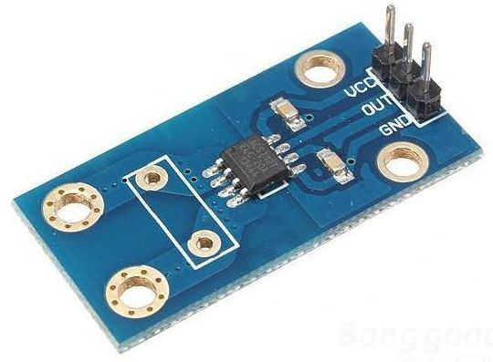
Sensor – ACS712 – Stroommeter
Hardware
Informatie (ENG)
The Allegro ACS712 provides economical and precise solutions for AC or DC current sensing in industrial, commercial, and communications systems. The device package allows for easy implementation by the customer. Typical applications include motor control, load detection and management, switched-mode power supplies, and overcurrent fault protection. The device is not intended for automotive applications.
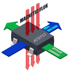
The device consists of a precise, low-offset, linear Hall sensor circuit with a copper conduction path located near the surface of the die. Applied current flowing through this copper conduction path generates a magnetic field which is sensed by the integrated Hall IC and converted into a proportional voltage. Device accuracy is optimized through the close proximity of the magnetic signal to the Hall transducer. A precise, proportional voltage is provided by the low-offset, chopper-stabilized BiCMOS Hall IC, which is programmed for accuracy after packaging.
The output of the device has a positive slope (>VIOUT(Q)) when an increasing current flows through the primary copper conduction path (from pins 1 and 2, to pins 3 and 4), which is the path used for current sensing. The internal resistance of this conductive path is 1.2 mΩ typical, providing low power loss. The thickness of the copper conductor allows survival of the device at up to 5× overcurrent conditions. The terminals of the conductive path are electrically isolated from the sensor IC leads (pins 5 through 8). This allows the ACS712 current sensor IC to be used in applications requiring electrical isolation without the use of opto-isolators or other costly isolation techniques.
The ACS712 is provided in a small, surface mount SOIC8 package. The leadframe is plated with 100% matte tin, which is compatible with standard lead (Pb) free printed circuit board assembly processes. Internally, the device is Pb-free, except for flip-chip high-temperature Pb-based solder balls, currently exempt from RoHS. The device is fully calibrated prior to shipment from the factory.
Top Features
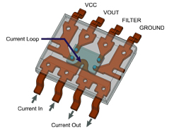
ACS712 chip:
Pinout
| Pin: | Functie: |
|---|---|
| +5v | +5V |
| OUT | DATA |
| GND | GND |
Arduino
Sluit de module aan volgens onderstaand overzicht:
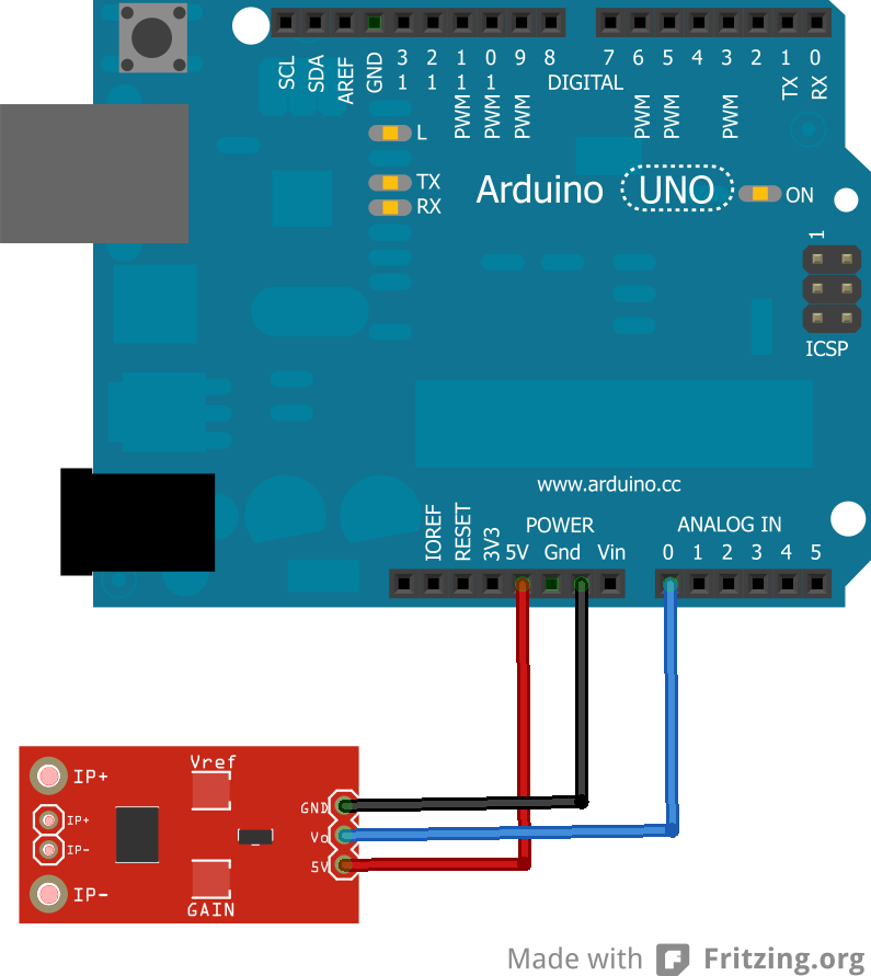
| Arduino Pin: | ACS712 Pin: |
|---|---|
| +5v | +5V |
| A0 | DATA |
| GND | GND |
Script #1
Sluit de stroommeter module aan zoals hierboven aangegeven.
|
1 2 3 4 5 6 7 8 9 10 11 12 13 14 15 16 17 18 19 20 21 22 23 24 25 |
void setup() { Serial.begin(9600); //Start Serial Monitor to display current read value on Serial monitor } void loop() { unsigned int x=0; float AcsValue=0.0,Samples=0.0,AvgAcs=0.0,AcsValueF=0.0; for (int x = 0; x < 150; x++){ //Get 150 samples AcsValue = analogRead(A0); //Read current sensor values Samples = Samples + AcsValue; //Add samples together delay (3); // let ADC settle before next sample 3ms } AvgAcs=Samples/150;//Taking Average of Samples //((AvgAcs * (5.0 / 1024.0)) is converitng the read voltage in 0-5 volts //2.5 is offset(I assumed that arduino is working on 5v so the viout at no current comes //out to be 2.5 which is out offset. If your arduino is working on different voltage than //you must change the offset according to the input voltage) //0.100v(100mV) is rise in output voltage when 1A current flows at input AcsValueF = ((AvgAcs * (5.0 / 1024.0)) - 2.5 )/0.100; Serial.println(AcsValueF);//Print the read current on Serial monitor delay(50); } |
Resultaat seriële monitor:
|
1 2 3 4 5 6 7 8 9 10 11 12 13 14 |
-0.00 0.00 -0.00 0.35 1.07 2.33 1.85 1.29 -0.00 0.00 1.84 3.64 7.81 0.00 |
Script #2
Dit script maakt geen gemiddelde waarden en komt wat zenuwachtiger over…
Sluit de stroommeter module aan zoals hierboven aangegeven.
|
1 2 3 4 5 6 7 8 9 10 11 12 13 14 15 16 17 18 19 20 21 22 23 24 25 26 27 |
int sensorValue; long current; void setup() { // Start de seriele poort. Serial.begin(9600); } void loop() { // Lees de waarde van de analoge ingang. sensorValue = analogRead( 0 ); // Print de analoge waarde naar de console. Serial.print(sensorValue, DEC); Serial.print( " = " ); // Pas het maximale bereik aan. if( sensorValue < 103 ) sensorValue = 102; else if( sensorValue > 921 ) sensorValue = 922; sensorValue -= 102; // Calculeer de stroom. current = ( ( sensorValue * 49951 ) >> 10 ) - 20000; // Print de waarde naar de console. Serial.print( (int)current, DEC ); Serial.println( " mA" ); // Wacht 100 milliseconden delay(100); } |
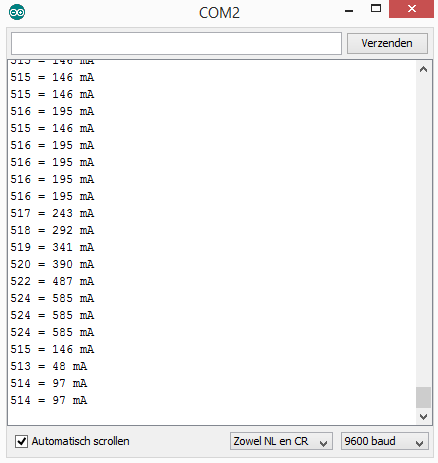
Het resultaat
Script #3
Dit script maakt gebruik van een speciale “filters” bibliotheek om waarden uit sinus waarden te berekenen…
|
1 2 3 4 5 6 7 8 9 10 11 12 13 14 15 16 17 18 19 20 21 22 23 24 25 26 27 28 29 30 31 32 33 34 35 36 37 38 39 40 41 42 43 44 45 46 |
/* This code works with ACS712 current sensor, it permits the calculation of the signal TRMS * Visit www.surtrtech.com for more details */ #include <Filters.h> //This library does a massive work check it's .cpp file #define ACS_Pin A0 //Sensor data pin on A0 analog input float ACS_Value; //Here we keep the raw data valuess float testFrequency = 50; // test signal frequency (Hz) float windowLength = 40.0/testFrequency; // how long to average the signal, for statistist float intercept = 0; // to be adjusted based on calibration testing float slope = 0.0752; // to be adjusted based on calibration testing //Please check the ACS712 Tutorial video by SurtrTech to see how to get them because it depends on your sensor, or look below float Amps_TRMS; // estimated actual current in amps unsigned long printPeriod = 1000; // in milliseconds // Track time in milliseconds since last reading unsigned long previousMillis = 0; void setup() { Serial.begin( 9600 ); // Start the serial port pinMode(ACS_Pin,INPUT); //Define the pin mode } void loop() { RunningStatistics inputStats; // create statistics to look at the raw test signal inputStats.setWindowSecs( windowLength ); // Set the window length while( true ) { ACS_Value = analogRead(ACS_Pin); // read the analog in value: inputStats.input(ACS_Value); // log to Stats function if((unsigned long)(millis() - previousMillis) >= printPeriod) { //every second we do the calculation previousMillis = millis(); // update time Amps_TRMS = intercept + slope * inputStats.sigma(); Serial.print( "\t Amps: " ); Serial.println( Amps_TRMS ); } } } |
Bronnen:
microcontroller-project.com
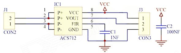
Schema
Afmetingen
GEEN GEGEVENS
Teardown
Datasheet
Fritzing

Downloads
GEEN GEGEVENS