Sensor – ADXL345 – 3-Assige versnellingsmeter
Hardware
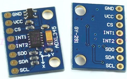
ADXL345 is een klein, laag vermogen, 3-assige versnellingsmeter met een hoge resolutie (13-bit) meting tot ± 16 g. Digitale uitgang van gegevens is opgemaakt als 16-bit. Uit te lezen via SPI of I2C.
Voor het meten van: statische (tilt) en dynamische (bewegingen/schokken) versnelling en detectie van: tap, dubbel tap, vrije val en inactief, het wordt in veel apparaten toegepast, waaronder in mobiele telefoons en tablets (voor schermrotatie e.d.)
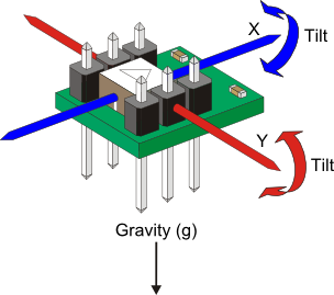
Accelerometers are devices that are capable of measuring the acceleration they experience relative to free-fall, the same acceleration living beings feel. As a consequence, accelerometers are incapable of measuring the acceleration of gravity, but can be used to measure the upwards acceleration that counters gravity when at rest. This acceleration is measured as 
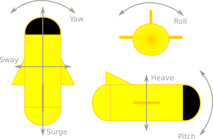
PITCH & ROLL ESTIMATION
Obtaining the pitch and roll angles is then a matter of being able to read the accelerometer, convert these readings to the g unit (1g = 9.8 m/s²), and apply the corresponding equations. The process of obtaining and converting the accelerometer readings depends on the accelerometer you are using, in my case, the ADXL345 in its basic configuration, provides 10-bit resolution for ±2g, but has several other ranges (±2g, ±4g, ±8g, ±16g) and resolutions (from 10 to 13 bits depending on the range) . Generalizing, the formula used to calculate the acceleration from the accelerometer readings is:

Once we have the correct acceleration components, we can proceed to calculate the different angles using the following equations:
}")
}")
For more information about where these equations come from, you can read the documentation I include at the end of this post. As you can see, the denominator of the pitch equation is defined to be always positive, so the equation itself only provides ![[-90, 90]](https://s0.wp.com/latex.php?latex=%5B-90%2C+90%5D&bg=ffffff&fg=555555&s=0 "[-90, 90]")
![[-180, 180]](https://s0.wp.com/latex.php?latex=%5B-180%2C+180%5D&bg=ffffff&fg=555555&s=0 "[-180, 180]")
Also, be aware that the roll equation is undefined when both 

REMOVING SHORT-TERM FLUCTUATIONS USING A LOW-PASS FILTER
At this point we already have a fully functional pitch & roll estimation system, but if we experiment with it we will discover that the readings fluctuate quite a bit and this may be very annoying for some applications. Removing these short-term fluctuations can be achieved by means of what is called a Low-Pass filter. This type of filter attenuates the higher frequencies of the signal, thus providing a smoother reading. The Low-Pass filter is easily implemented by using the following equation:
 \cdot y_{t - 1}")
Where 


Bron: https://theccontinuum.com/2012/09/24/arduino-imu-pitch-roll-from-accelerometer/
Pinout

| Pin: | Functie: |
|---|---|
| 1 | SCL (serial clock) |
| 2 | SDA (serial data) |
| 3 | SD0 (serial data output) |
| 4 | INT1 |
| 5 | INT2 |
| 6 | CS (Chip Select) |
| 7 | VCC 3.3v+ |
| 8 | GND |
Arduino
Sluit de sensor aan volgens onderstaand overzicht:
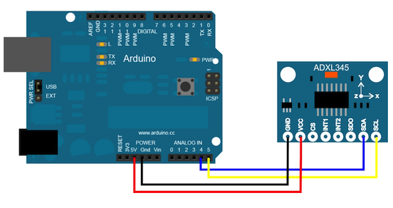
| Arduino pin: | ADXL345 pin: |
|---|---|
| A4 | SDA (serial data) |
| A5 | SCL (serial clock) |
| 3.3v+ | VCC 3.3v+ |
| GND | GND |
Script
Sluit de Accelerometer module aan zoals hierboven aangegeven.
|
1 2 3 4 5 6 7 8 9 10 11 12 13 14 15 16 17 18 19 20 21 22 23 24 25 26 27 28 29 30 31 32 33 34 35 36 37 38 39 40 41 42 43 44 45 46 47 48 49 50 51 52 53 54 55 56 57 58 59 60 61 62 63 64 |
#include <Wire.h> #define DEVICE (0x53) // Device address as specified in data sheet byte _buff[6]; char POWER_CTL = 0x2D; //Power Control Register char DATA_FORMAT = 0x31; char DATAX0 = 0x32; //X-Axis Data 0 char DATAX1 = 0x33; //X-Axis Data 1 char DATAY0 = 0x34; //Y-Axis Data 0 char DATAY1 = 0x35; //Y-Axis Data 1 char DATAZ0 = 0x36; //Z-Axis Data 0 char DATAZ1 = 0x37; //Z-Axis Data 1 void setup() { Wire.begin(); // join i2c bus (address optional for master) Serial.begin(9600); // start serial for output. Make sure you set your Serial Monitor to the same! Serial.print("init"); //Put the ADXL345 into +/- 4G range by writing the value 0x01 to the DATA_FORMAT register. writeTo(DATA_FORMAT, 0x01); //Put the ADXL345 into Measurement Mode by writing 0x08 to the POWER_CTL register. writeTo(POWER_CTL, 0x08); } void loop() { readAccel(); // read the x/y/z tilt delay(50); // only read every 0,5 seconds } void readAccel() { uint8_t howManyBytesToRead = 6; readFrom( DATAX0, howManyBytesToRead, _buff); //read the acceleration data from the ADXL345 // each axis reading comes in 10 bit resolution, ie 2 bytes. Least Significat Byte first!! // thus we are converting both bytes in to one int int x = (((int)_buff[1]) << 8) | _buff[0]; int y = (((int)_buff[3]) << 8) | _buff[2]; int z = (((int)_buff[5]) << 8) | _buff[4]; Serial.print("x: "); Serial.print( x ); Serial.print(" y: "); Serial.print( y ); Serial.print(" z: "); Serial.println( z ); } void writeTo(byte address, byte val) { Wire.beginTransmission(DEVICE); // start transmission to device Wire.write(address); // send register address Wire.write(val); // send value to write Wire.endTransmission(); // end transmission } // Reads num bytes starting from address register on device in to _buff array void readFrom(byte address, int num, byte _buff[]) { Wire.beginTransmission(DEVICE); // start transmission to device Wire.write(address); // sends address to read from Wire.endTransmission(); // end transmission Wire.beginTransmission(DEVICE); // start transmission to device Wire.requestFrom(DEVICE, num); // request 6 bytes from device int i = 0; while(Wire.available()) {// device may send less than requested (abnormal) _buff[i] = Wire.read(); // receive a byte i++; } Wire.endTransmission(); // end transmission } |
Het resultaat

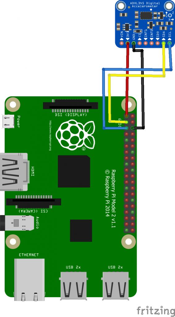
Raspberry Pi
Connect the sensor like:
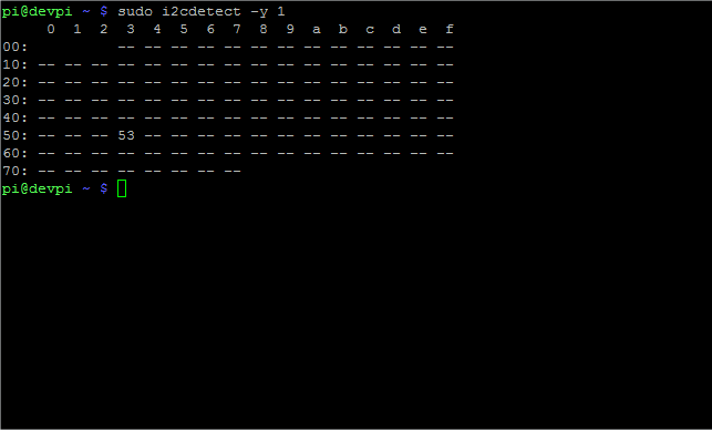
The I2C ADXL module will be found with adress 0x53:
Script
Use the adafruit library to easy read out your sensor.
|
1 2 3 4 5 6 7 8 9 10 11 12 13 14 15 16 17 18 19 20 21 22 23 24 25 26 27 28 29 30 31 32 33 34 35 36 37 38 39 40 41 42 43 44 45 46 47 48 49 50 51 |
# Simple demo of of the ADXL345 accelerometer library. Will print the X, Y, Z # axis acceleration values every half second. # Author: Tony DiCola # License: Public Domain import time # Import the ADXL345 module. import Adafruit_ADXL345 # Create an ADXL345 instance. accel = Adafruit_ADXL345.ADXL345() # Alternatively you can specify the device address and I2C bus with parameters: #accel = Adafruit_ADXL345.ADXL345(address=0x54, busnum=2) # You can optionally change the range to one of: # - ADXL345_RANGE_2_G = +/-2G (default) # - ADXL345_RANGE_4_G = +/-4G # - ADXL345_RANGE_8_G = +/-8G # - ADXL345_RANGE_16_G = +/-16G # For example to set to +/- 16G: #accel.set_range(Adafruit_ADXL345.ADXL345_RANGE_16_G) # Or change the data rate to one of: # - ADXL345_DATARATE_0_10_HZ = 0.1 hz # - ADXL345_DATARATE_0_20_HZ = 0.2 hz # - ADXL345_DATARATE_0_39_HZ = 0.39 hz # - ADXL345_DATARATE_0_78_HZ = 0.78 hz # - ADXL345_DATARATE_1_56_HZ = 1.56 hz # - ADXL345_DATARATE_3_13_HZ = 3.13 hz # - ADXL345_DATARATE_6_25HZ = 6.25 hz # - ADXL345_DATARATE_12_5_HZ = 12.5 hz # - ADXL345_DATARATE_25_HZ = 25 hz # - ADXL345_DATARATE_50_HZ = 50 hz # - ADXL345_DATARATE_100_HZ = 100 hz (default) # - ADXL345_DATARATE_200_HZ = 200 hz # - ADXL345_DATARATE_400_HZ = 400 hz # - ADXL345_DATARATE_800_HZ = 800 hz # - ADXL345_DATARATE_1600_HZ = 1600 hz # - ADXL345_DATARATE_3200_HZ = 3200 hz # For example to set to 6.25 hz: #accel.set_data_rate(Adafruit_ADXL345.ADXL345_DATARATE_6_25HZ) print('Printing X, Y, Z axis values, press Ctrl-C to quit...') while True: # Read the X, Y, Z axis acceleration values and print them. x, y, z = accel.read() print('X={0}, Y={1}, Z={2}'.format(x, y, z)) # Wait half a second and repeat. time.sleep(0.5) |
Raspberry Pi Library
Python code to use the ADXL345 triple-axis accelerometer over I2C with a Raspberry Pi or BeagleBone Black.
Installation
To install the library from source (recommended) run the following commands on a Raspberry Pi or other Debian-based OS system:
|
1 2 3 4 5 6 |
sudo apt-get install git build-essential python-dev cd ~ git clone https://github.com/adafruit/Adafruit_Python_ADXL345.git cd Adafruit_Python_ADXL345 sudo python setup.py install |
Alternatively you can install from pip with:
|
1 2 |
sudo pip install adafruit-adxl345 |
Note that the pip install method won’t install the example code.
Download github: https://github.com/adafruit/Adafruit_Python_ADXL345
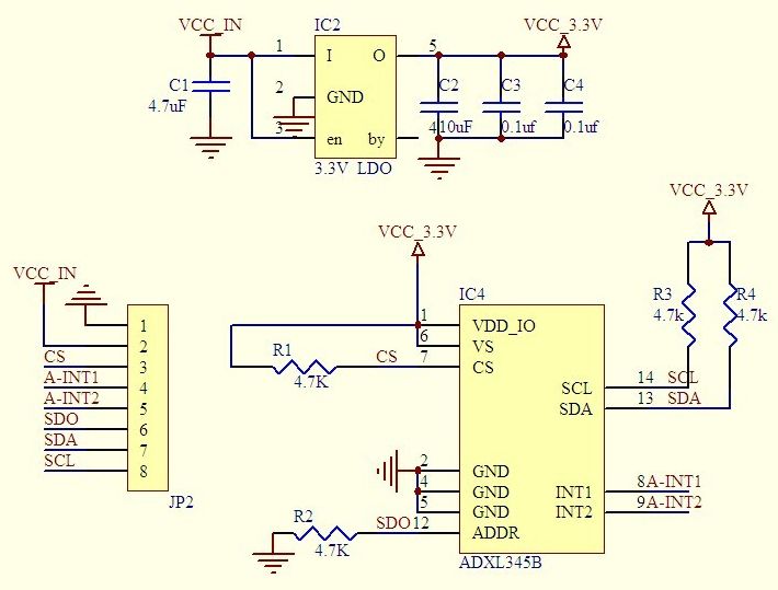
Schema
Teardown
GEEN GEGEVENS
Datasheet
Fritzing
GEEN GEGEVENS
Downloads
GEEN GEGEVENS