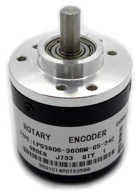
Sensor – LPD3806 – Optical Rotary Encoder
Hardware
Informatie (ENG)
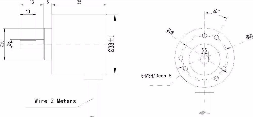
The off-axis platform is: height 5mm, φ20mm; fixing hole is: M3 screw, 3 mounting holes are on the circle of 30, and the other 3 mounting holes are on 28 circles; side outlet.
Wiring:
AB two-phase output rectangular orthogonal pulse, the circuit output is NPN open collector output type, this output type can be directly connected with single-chip microcomputer or PLC with internal pull-up resistor, such as 51 single-chip or Mitsubishi PLC (PLC input mode Should be connected to the switch to 0V function), Note: If the encoder is not connected to the device, the oscilloscope cannot be directly oscillating (the open collector output has no voltage output when there is no pull-up resistor). Two pull-up resistors are added to the two-phase output of the AB;
Used to measure the rotation speed, angle, acceleration and length of an object.
It is suitable for intelligent control of various displacement change measurement, automatic fixed length automatic suede machine, steel fixed length cutting controller, civil height measuring human body scale, college student competition robot, etc.
It has the advantages of small size, light weight, convenient installation and high cost performance.
A phase and B phase output lines must not be connected directly to VCC, otherwise, the output three-stage tube will be burned.
Pinout
Arduino
Sluit de module aan volgens onderstaand overzicht:
Bron: https://www.youtube.com/watch?v=QE4IQlwOgiA

| Arduino pin: | BMP280 pin: |
|---|---|
| +5V | +5V (VCC) |
| GND | GND |
| A5 | SCL Serial Clock (line) |
| A4 | SCA Serial Clock (data) |
Script
Bron: https://github.com/jumejume1/Arduino/blob/master/ROTARY_ENCODER/ROTARY_ENCODER.ino
|
1 2 3 4 5 6 7 8 9 10 11 12 13 14 15 16 17 18 19 20 21 22 23 24 25 26 27 28 29 30 31 32 33 34 35 36 37 38 39 40 41 42 |
volatile unsigned int temp, counter = 0; //This variable will increase or decrease depending on the rotation of encoder void setup() { Serial.begin (9600); pinMode(2, INPUT_PULLUP); // internal pullup input pin 2 pinMode(3, INPUT_PULLUP); // internal pullup input pin 3 //Setting up interrupts //A rising pulse from encoder activated ai0(). AttachInterrupt 0 is DigitalPin nr 2 on Arduino. attachInterrupt(0, ai0, RISING); //B rising pulse from encodenren activated ai1(). AttachInterrupt 1 is DigitalPin nr 3 on Arduino. attachInterrupt(1, ai1, RISING); } void loop() { // Send the value of counter if( counter != temp ){ Serial.println (counter); temp = counter; } } void ai0() { // ai0 is activated if DigitalPin nr 2 is going from LOW to HIGH // Check pin 3 to determine the direction if(digitalRead(3)==LOW) { counter--; } else { counter++; } } void ai1() { // ai0 is activated if DigitalPin nr 3 is going from LOW to HIGH // Check with pin 2 to determine the direction if(digitalRead(2)==LOW) { counter++; } else { counter--; } } |
Please note that every rotation is pulses x 2, so a 600 pulse will give 1200 as number.
Results:
|
1 2 3 4 5 6 7 8 9 10 11 12 13 14 15 16 17 18 19 20 21 22 23 24 25 26 27 28 29 30 31 32 33 34 35 36 |
65399 65405 65410 65417 65430 65445 65461 65478 65494 65508 65521 65533 8 13 19 26 33 39 45 51 57 62 67 73 79 85 90 95 101 107 114 121 128 135 143 151 |
Arduino Library
GEEN GEGEVENS
Raspberry Pi
The encoder has 4 connections: power, ground, phase A, and phase B. The power ground should be connected to an external power source (do not use the internal Raspberry Pi power pin). The power source, encoder, and Raspberry Pi should have a common ground. The phase A and phase B connections should be connected to the 17 and 27 cobbler pins (GPIO pins).
Two ![10 [k \Omega]](https://aleksandarhaber.com/wp-content/ql-cache/quicklatex.com-a8dfb80e44057d6c11192728d69f5200_l3.svg "Rendered by QuickLaTeX.com") pull-up resistors should be connected to the power and phase A and phase B connections.
pull-up resistors should be connected to the power and phase A and phase B connections.

The figure below shows the voltage readings between phase A (phase B) and the ground for counterclockwise and clockwise rotations of the encoder shaft.
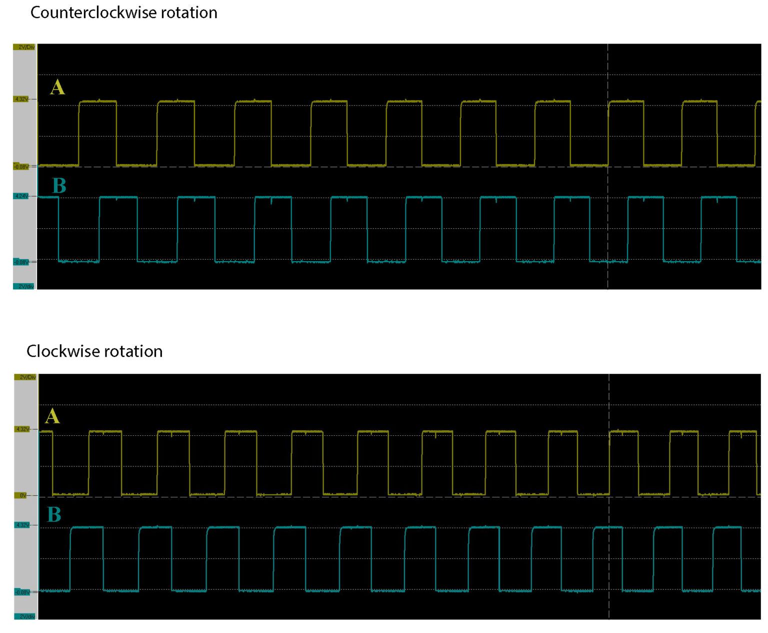
We can observe that in the counterclockwise case, phase A leads the phase B. On the other hand, in the clockwise direction phase B leads the phase A. This is an important observation that enables us to develop the C/C++ code for measuring the rotation angle.
We can introduce two states for phases A and B. The state of phase A (phase B), denoted by “phase A” (“phase “), can be 0 or 1. The zero state corresponds to a low volage value (0 [V]), and the high voltage corresponds to a high voltage value (5 [V]). The following table visualizes the changes.
| STATE A | STATE B | A TRIGGERS (NEXT STATE A, DIRECTION) |
B TRIGGERS (NEXT STATE B, DIRECTION) |
|---|---|---|---|
| 0 | 0 | (1,+) | (1,-) |
| 0 | 1 | (1,-) | (0,+) |
| 1 | 0 | (0,-) | (1,+) |
| 1 | 1 | (0,+) | (0,-) |
|
1 2 3 4 5 6 7 8 9 10 11 12 13 14 15 16 17 18 19 20 21 22 23 24 25 26 27 28 29 30 31 32 33 34 35 36 37 38 39 40 41 42 43 44 45 46 47 48 49 50 |
#include <wiringPi.h> #include <iostream> using namespace std; long encoder; int stateA=0; int stateB=0; float angle=0; int wireA=0; //BCM 17 int wireB=2; //BCM 27 void A() { if (stateA==stateB) { encoder++; } stateA=digitalRead(wireA); return; } void B() { if (stateA==stateB) { encoder--; } stateB=digitalRead(wireB); return; } int main() { wiringPiSetup(); wiringPiISR(wireA, INT_EDGE_BOTH,&A); wiringPiISR(wireB, INT_EDGE_BOTH,&B); while(1) { angle=encoder*0.3; cout<<"Angle is:"<<angle<<endl; } } |
The function wiringPiISR() is used to define an interrupt. The first argument is the pin number. The second argument tells the compiler when the interrupt should be activated (options are: rising edge, falling edge, and both rising and falling edges). In our case, the interrupt should be activated if the edge of the signal is rising or falling. The third argument is the function that should be called when the interrupt is activated. In our case, these are the functions A() and B() defined on the lines 14-32. For example, when the signal A rises from a digital low ( 0 [V] -binary 0) to a digital high value (5 [V] -digital 1), then the function A() is called. The code line 46 is used to convert the encoder readings into the angle. For the full rotation, we have measured 1200 value of the variable “encoder”. That is why we have a constant 0.3 multiplying the “encoder” variable that stores the encoder increments (0.3=360 [degrees] /1200 [increments]).
Bron: https://aleksandarhaber.com/incremental-rotary-encoders-with-raspberry-pi-lpd3806-600bm/
Afmetingen
Schema
Teardown
Bron: https://wemakethings.net/2014/05/26/rotary-encoder-teardown/
Recently we’ve purchased a couple of these cheap chinese rotary quadrature encoders with markings LPA3806-600BM-G5-24C on them. I’ve went and looked inside of one of them as documentation available online is rather scarce.
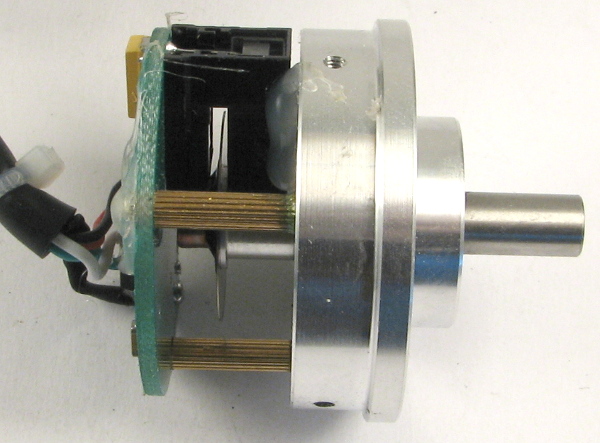
There’s not much to it – just what you would expect – a quadrature disc, and a LED/phototransistor module.
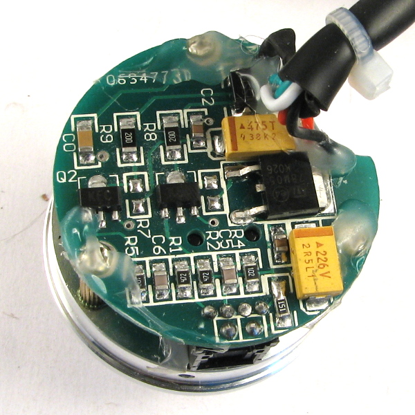
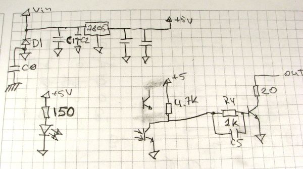
The circuit draws around 30mA. Outputs are open collector with 20 Ohm resistors for protection. Nice to see that they have added a “fools diode” D1 that will short out your power suply if you switch GND and VCC connections.
One thing to note – the encoder has a 5V linear regulator inside, so you want to power it with at least 7V power supply. Make sure the power dissipation in the internal regulator is within reasonable limits. The heat management is not spectacular in the encoder – case is connected to the chasis ground, not circuit ground and the internal LM7805 regulator in D-PAK packege relies on a big ground plane to act as a heatsink.
Let’s say we are powering it off 12V supply. The regulator has to dissipate (12V-5V) * 0.030A = 0.210W. Considering the worst case scenarion of RthJA beeing 100°C/W it would experience 21°C rise of junction temperature above the ambient. Considering the ambient to be 85°C we get the junction temperature to be at 106°C which is a bit too close to the absolute maximum of 125°C for my taste. As it’s a chinese noname product, I’d aim for the junction temperature not higher than 100°C. YMMV
Datasheet
GEEN GEGEVENS
Fritzing
GEEN GEGEVENS
Downloads
GEEN GEGEVENS