Sensoren – Magnetometer kalibratie

Het volgende stuk beschrijft het kalibreren van een Magnetometer is van deze website gehaald en is in het Engels:

If you bought the cheap magnetomter module like HMC5883L you can not use it without calibration. Measurement of magnetic field will be subjected to distortion. There are two categories of these distortions: the hard iron distortions and the soft iron distortions. The hard iron errors refer to the presence of magnetic fields around the sensor (magnets, power supply wires) and are related to measurement offset errors, while the soft iron errors refer to the presence of ferromagnetic materials around the sensor, which skew the density of the Earth’s magnetic field locally and are related to scaling offset errors. You can read more information about these distortions here.
In other words, to get the correct magnetometer data you should get the calibrated magnetometer data. One of the ways to resolve this problem: you should apply the bias to the vector of the non calibrated magnetometer data (X, Y, Z coordinates) and then multiply the transformation matrix by this resulting vector:

In this case the magnetometer calibration is the process of getting the transformation matrix and the bias. To get these data you can use the MagMaster program.
Example of using the MagMaster
Hardware:
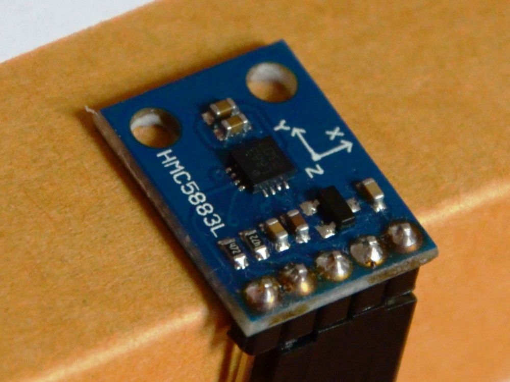
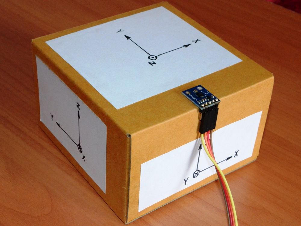
- HMC5883L magnetometer module (GY-273 version, picture 2)
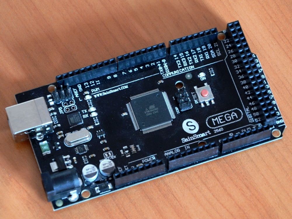
- Arduino Mega 2560 (chinese SaintSmart Mega 2560 version, picture 3)
Software:
- MagMaster (placed in MagMaster folder)
- MagViewer (placed in MagMaster folder)
Firmware:
- Arduino Sketch (placed in MagMaster folder)
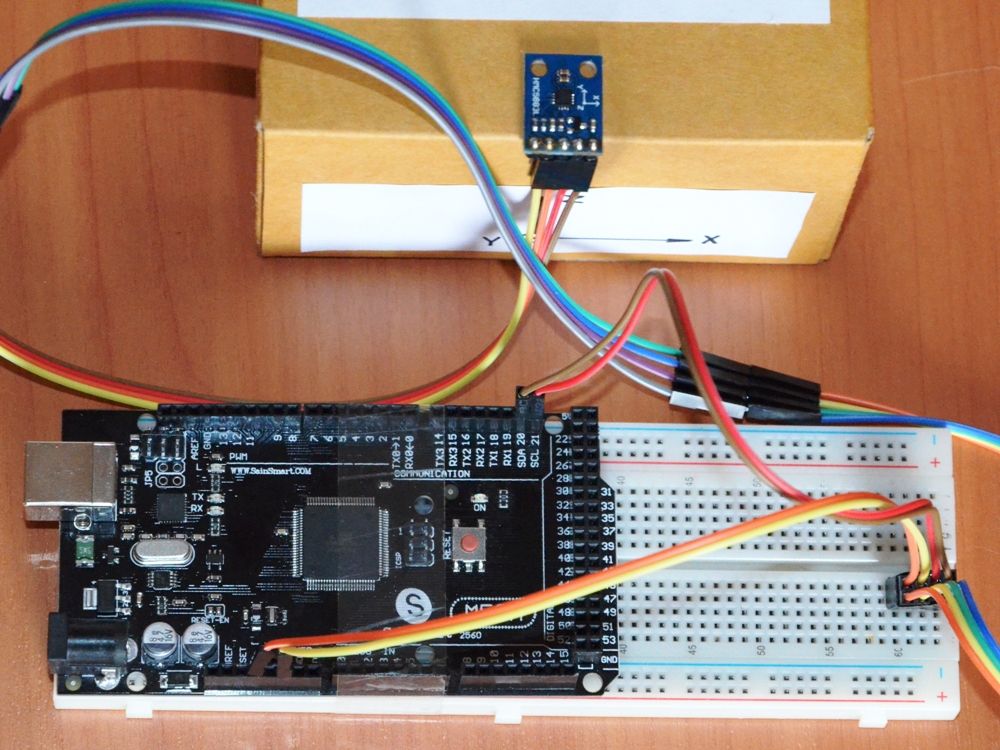
Connect the magnetometer module to the arduino board via I2C bus (picture 4). Upload the arduino sketch to the arduino board (see “Arduino_Code” folder in the “MagMaster” folder). This arduino sketch requires the HMC5883L library, copy the folder “HMC5883L” (placed in “Arduino_Code” folder) to the folder “C:\Program Files\Arduino\libraries”.
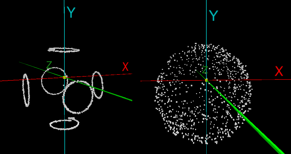
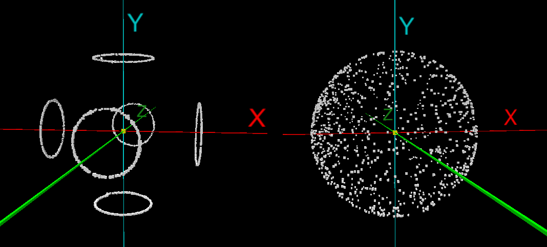
Then run the MagViewer.exe, select the serial port of the arduino board (the boud rate of the seraial port should be 9600 bps) and click “Run MagViewer”. Now you can see the coordinates of the magnetometer data vector in 3D space on a real time (picture 5, video 1, 2). These data are not calibrated yet.
If you see the points of the magnetometer vector coordinates in 3D space the arduino board and the PC connection works right.
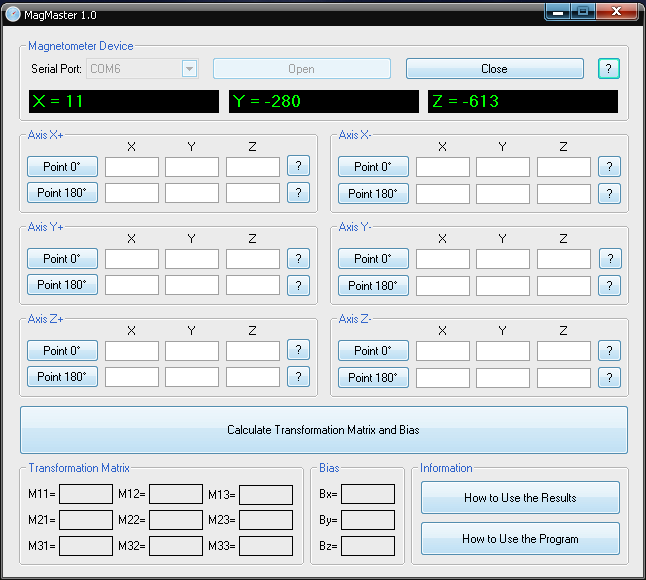
Now close the MagViewer window and run the MagMaster.exe (picture 6). Select the serial port of the arduino board. The green strings X, Y, Z will indicates the coordinates of the magnetometer vector.
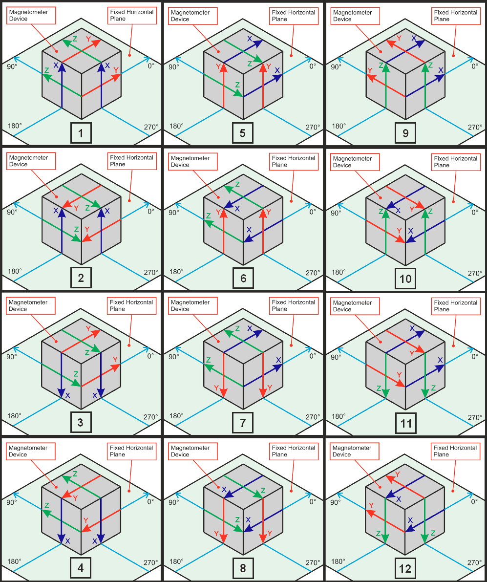
Place the magnetometer module as shown on the picture 8.1 and click “Point 0” button of the “Axis X+” groupbox. For the placement of the module you can use the wooden bar or the paper box (picture 7). If you can not connect your magnetometer device to PC then you can use any other way to get to know the magnetometer data. You can enter these data in the program manually.
Place the magnetometer as shown on the picture 8.2 and click “Point 180” button of the “Axis X+” groupbox and so on. You should do in the following way:
- Picture 8.1: “Point 0”, “Axis X+”
- Picture 8.2: “Point 180”, “Axis X+”
- Picture 8.3: “Point 0”, “Axis X-“
- Picture 8.4: “Point 180”, “Axis X-“
- Picture 8.5: “Point 0”, “Axis Y+”
- Picture 8.6: “Point 180”, “Axis Y+”
- Picture 8.7: “Point 0”, “Axis Y-“
- Picture 8.8: “Point 180”, “Axis Y-“
- Picture 8.9: “Point 0”, “Axis Z+”
- Picture 8.10: “Point 180”, “Axis Z+”
- Picture 8.11: “Point 0”, “Axis Z-“
- Picture 8.12: “Point 180”, “Axis Z-“
You should fill the table. After that click “Calculate Transformation Matrix and Bias” and get the required matrix and bias (picture 9).

The transformation matrix and the bias are got. Now you can calculate the calibrated magnetometer data in your device on a real time with using the matrix and the bias as shown on picture 1. The example of the arduino sketch of using this calculation you can find in the “Arduino_Test_Results” folder.
You can apply the sphere radius stabilization algorithm to your program (use for it the Arduino_Radius_Stabilization folder placed in MagMaster folder).
The calibrated magnetometer vector coordinates in 3D space with the radius stabilization shown on the picture 10 and video 3, 4.
Using of the arduino is only example, you can easy adopt the arduino code for any other system and use the MagMaster program with it.