Sketchup plugin – Slicer5
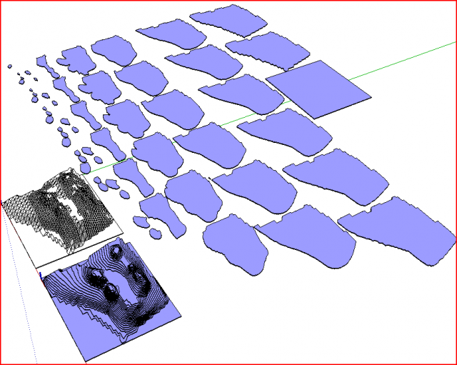
Met de Slicer plugin voor Sketchup kun je je model in stukken snijden, je kan dan in 1 oogopslag zien of het model goed is, erg handig voor reparatie van je model.
Let op het model MOET dicht zijn (manifold) anders kan de slicer zijn werk niet doen, gebruik daarvoor deze plugin: Manifold
Sketchup compatibiliteit: SketchUp 8+, getest en werkend met SketchUp 2014, SketchUp 2015
Ps. TIG Slicer – v5.15 – werkt niet opSketchUp 2015
Download @ SketchUcation
Installatie van Sketchup plugins/tools/libraries: Sketchup info
Menu toegang:
Extensions > Slicer5
Gebruik (ENG):
*’Z’ is the default
The ‘Axis’ is the RGB/XYZ axis along which the Slices will be taken.
If you choose a dual axis [XY/XZ/YZ or AZ or RZ] then Slices will be
taken on those two axes and additional dialogs will appear. see later…
There are two additional ‘A’ and ‘R’.
If you choose ‘A’ then a special dialog asks for the Angle of the
vertical Slices around the Z_axis – see details later…
If you choose ‘R’ the vertical Slices with be arranged ‘Radially’,
offset from the Origin [0,0,0] – so locate the Sliced Object relative
to the Origin as you require, BEFORE activating this tool…
With this option the Inset_Start/End is always auto-set to ‘0’, but if
the Origin is outside of the bounds of the Sliced Object then the
First/Last Slice are adjusted to inset from the subtended extremities so
that their outermost sides align with the Sliced Object’s extremities.
With this option the Spacing is also auto-set to ‘0’, and the Slices are
equally spaced – therefore there is a dialog asking for the ‘Number of
Spaces’, showing the Angle subtended from the Origin to the extremities
of the Sliced Object. As with other axes if you specify say 7 Spaces
you will get 8 Slices, unless the Origin is with or touching the bounds
of the Sliced Object on a side, in which case the number of Slices is
the number of Spaces. If the Origin is inside the Sliced Object then
the rotated set of Slices will be spaced by the number specified, but
because they’ll all overlap the visual spaces will appear ‘doubled’,
7 looking like 14 from the concentric 7 Slices.
There is an ‘AZ’ option: this is like the ‘A’ Angled option
combined with a second Sliced set in the Z-direction, like other dual-
axis options you can add Slots etc, because of the slanting nature of
results you might find that you need to make some manual adjustments to
the form of some angled slices where they project through the ‘skin’ of
the Sliced Object, particularly for Start/End Slices that are exactly on
the extremities of the Object; therefore it’s recommended you use
Inset_Start/End Slices on the Angled Slices to ensure these Slices
fall within the volume of the Sliced Object…
see later…
If the Axis==X/Y/Z/A and the Thickness==Spacing there is an
additional dialog ‘Add the Outlines of Adjacent Slices’ – Yes/No.
If you answer Yes then after the Slices have been made an additional
status-bar message ‘Outlining..’ appears and ‘The Adjacent Slices’ are
‘imprinted’ onto each Slice as appropriate – this ‘Outline’ is in the
form of a group named ‘OLIN’, on layer ‘SLCR-OLIN’. This may be useful
when making certain types of models [like site contours], so as you
build a physical model up from the bottom Slice [highest numbered]
it will show the Outline of the next Slice above it which can help in
aligning it – see Export section later…
There is an ‘RZ’ option: this is like the ‘R’ Radial option
combined with a second Sliced set in the Z-direction, like other dual-
axis options you can add Slots etc, because of the slanting nature of
results you might find that you need to make some manual adjustments to
the form of some angled slices where they project through the ‘skin’ of
the Sliced Object, particularly where Start/End Slices that are exactly
on the extremities of the Object…
see later…
Select the desires Axis from the list.
Spacing:
default is 2″ or 50mm
Sets the center-to-center Spacing of the Slices.
The slices are set-out ‘Centralized’ as specified – on Slice or Gap.
The first and last Slices Spacings are automatically adjusted to fit
within the bounds of the Sliced Object and any Insets [see below].
The typed in value assumes current-units, you can add a suffix to use an
alternative – e.g. if you are working in ‘cm’, typing ‘5’ gives 5cm, or
typing ’50mm’ gives 5cm too.
If you enter 0 it assumes you want to set a total number of ‘spacings’,
with the actual spacing dimension calculated and adjusted to suit –
a second dialog will ask for details of this later [see below]…
Thickness:
default is 1/8″ or 3mm
Sets the slice Thickness, it cannot be more than the Spacing.
The typed in value assumes current-units, you can add a suffix to use an
alternative – e.g. if you are working in ‘cm’, typing ‘5’ gives 5cm, or
typing ’50mm’ gives 5cm too.
Inset at Start:
default 0
Sets the first Slice’s inset, 0=flush with Sliced Object’s bounds.
Inset at End:
default 0
Sets the last Slice’s inset, 0=flush with Sliced Object’s bounds.
Centralization:
default ‘Slice’
By default for a fixed Spacing the slices’ creation starts centrally from the
sliced-object’s bounds center and it steps out in both directions equally,
so you always get an odd number of slices.
If you are slicing something that’s 12″ into 4″ spacing with 4″ thick slices
then you get 3 slices, BUT if you chose 3″ spacing and 3″ thickness you would
NOT get 4 BUT 5 slices, with the first and last slices overlapping by 1.5″ ***.
However, if you choose the alternative ‘Centralization’ by ‘Gap’ then the
slicing generation shunts so that you get 4 sizes in the above example.
So depending on the format of your slicing and your desire for odd or even slice
counts, you can choose between Centering the slicing on the ‘Slice’ or on the ‘Gap’…
The Centralization setting will have no effect on ‘R’ [Radial] types of slicing,
it but works with all Axial [XYZ] and ‘A’ [Angled] slicing formats…
*** This Centralization setting also has no effect on the setting-out when you
specify a ‘0’ Spacing, since all of the slices will be ‘evenly spaced’ anyway –
slices will be centered with an ‘even’ Spaces counts, and gaps centered with an
‘odd’ Spaces count: with the actual Spacing of the slices auto-adjusted to suit
the overall size of the object and number of Spaces you have specified.
Add References ?
default ‘Yes’
Adds a ‘TEXT’ reference tag to the bottom-left corner of each Slice.
Although the tag is always on the Slice’s face plane, it might not
always be on the face itself, but can be relocated manually as desired.
If the ‘Radial’ option is chosen, then the tag’s location is still on
the plane of the Slice, BUT it might be located unexpectedly away from
the bottom-left corner; this can also cause tags to overlap other Slices
inside Flattened sets, but the tag or the Slices are easily relocated
manually.
If the system-font ‘Txt.ttf’ is installed, then it will be used to make
a ‘stick’ font flat-text group [TEXT] on layer ‘SLCR-TEXT’; otherwise
the current 3d_Text font will be used.
The Text Height is set in the next option…
Text Height:
default 0.5″ or 12mm
Sets the Text Height of the Reference ‘TEXT’ [if specified].
Flatten ?
default ‘Yes’
This makes a flattened set of the Slices.
It is a group located to the max-extents of the Sliced Object.
‘Cancel’
stops the tool
‘OK’
runs the tool.
If you chose a dual axis [XY/XZ/YZ] then a second dialog asks
you for further options for the Slice2 set: its title/status-bar
displays the axis of the Slice2 set, typically ‘Z’ or ‘Y’:
Spacing:
generally as the Spacing above…
It defaults to that Spacing, but allows you to specify a different
Spacing value for the second set of Slices.
Thickness:
generally as the Thickness above…
It defaults to that Thickness, but allows you to specify a different
Thickness value for the second set of Slices.
Inset at Start:
generally as the Inset at Start above…
default Inset at Start
Sets the first Slice2’s inset, 0=flush with Sliced Object’s bounds.
Inset at End:
generally as the Inset at End above…
default Inset at Start
Sets the last Slice2’s inset, 0=flush with Sliced Object’s bounds.
Slot ?
default is ‘Yes’ [but reverts to ‘No’ if Thickness==0].
If ‘Yes’ this will ‘Slot’ the Intersecting Slices.
BUT if either of the Slices’ Thickness==0 then there will be no
Slotting done, and the value of ‘Slotting’ defaults to ‘No’.
Note that adding ‘Slots’ greatly increases the processing time needed,
but is often necessary is a 3d assembly is envisaged…
Tolerance:
If you are Slotting slices and using a CNC router it’s advisable to
make the Slots slightly bigger than the Thickness – typically 0.2mm.
Half of the Tolerance is shaved off each of the sides of each Slot.
The total width of each Slot is thereby made bigger than its mating
Slots’ Thickness by that additional Tolerance.
The default is 0.
Enter the required value.
If Slotting is set to ‘No’, Tolerance is auto-set to 0.
Overcut:
If you are Slotting slices and using a CNC router it’s advisable to
make the Slots slightly longer so that the internal rounded corners left
by the router-bit do not foul the mating Slice’s Slot ends.
This is sometimes called ‘dog-boning’ or ‘mouse-ears’.
Typically you set this to be the router-bit diameter – say 3/4/5/6mm
[it’ll be made half of this, as the router-bit’s radius is always used]
The default is 0.
Enter the required value.
It should never be greater than the Thickness, because a router-bit of
that diameter wouldn’t cut the Slot correctly anyway!
If ‘Slotting’ is set to ‘No’, Overcut is auto-set to 0.
‘Cancel’
stops the tool
‘OK’
runs the tool.
NOTE:
If you have specified a Spacing of ‘0’ for an axis then
another dialog opens asking you for addition values for the ‘Spaces’…
default is 1 – Note that 1 is the minimum number of spaces in a Sliced
set – producing a start and an end Slice only.
The prompt shows the axis and the total size in current-units – e.g.
‘Spaces [X 1234mm]:’
Enter the number of ‘Spaces’ required on that axis.
For example, if you want the Slices to be around 50mm center-to-center
then do a quick calculation – 1234/50=24.68, so use 24 or 25 spaces
depending on those Slices’ Thickness and your preferred ‘gaps’…
If you simply want a central Slice type in 2 Spaces, or for 2 internal
Slices use 3 Spaces etc…
If you have specified a dual axis [XY/XZ/YZ] AND have entered a
Spacing=0 for BOTH axes, then there will be a second option added to the
dialog, e.g. for an XY axis set:
‘Spaces [X 1234mm]:’
‘Spaces [Y 5678mm]:’
Enter the required ‘Number of Spaces’ for both axes.
You may use this approach instead of the Centralization by Slice/Gap option…
There is an Angle option [A], if you select that AND Spacing=0
then you are asked for the ‘Number of Spaces’, with a prompt that says
‘Spaces [A=12.5° 1234mm]:’m to remind you that you are in the Angled
Axis mode.
There is also a Rotation option [R] – if you select that then
Spacing=0 automatically, and you are asked for the ‘Number of Spaces’
[default=3] with the prompt ‘Spaces [R 23.4°]:’, showing the Angle from
the Origin to the two subtended extremities of the Sliced Object.
‘Cancel’
stops the tool
‘OK’
runs the tool.
If you specified the Axis as ‘A’ a special dialog asks for the Angle.
Slices can only be made rotated around the Z-axis using this option, so
rotate the Sliced Object in 3d if the Angled slices are required canted
at any other relationship. The Angle is entered in degrees, a +ve Angle
rotates the Slices counter-clockwise and a -ve Angle clockwise.
Note, 0=X_axis, 90=Y_axis: the rotation is around the Z-axis.
The specified Spacing is measured perpendicular to the Slices.
‘Cancel’
stops the tool
‘OK’
runs the tool.
Slicer5 now runs…
It reports its progress in the Status Bar…
The Slice-set is given a unique random 4 digit code – e.g. ‘1234’
The Slices are assembled inside a group named ‘SLICES-1234’, placed
exactly over the Sliced Object, at the specified Spacing etc.
This group is made on its own layer:
‘SLCR-ZZZZ’ for Z-axis Slices
‘SLCR-YYYY’ for Y-axis Slices
‘SLCR-XXXX’ for X-axis Slices
‘SLCR-AAAA’ for Angled Slices
‘SLCR-RRRR’ for Radial Slices
If specified the individual Slice-components have reference tag-groups
added, named ‘TEXT’, reading ‘Z001’ to ‘Z999’, the prefix varying with
the specified axis [XYZ]. This TEXT is put on layer ‘SLCR-TEXT’.
The Slice-components themselves are named to match their reference with
the Slice-set’s code as a prefix – e.g. ‘1234-Z001’.
The Slices are colored to match their axis – Red/Green/Blue==X/Y/Z.
The materials are called, respectively, ‘SLCR-XXXX’, ‘SLCR-YYYY’ and
‘SLCR-ZZZZ’.
Angled Slices are colored ‘SLCR-AAAA’ – mid-gray.
Rotated Slices are colored ‘SLCR-RRRR’ – pale-amber.
If a Flattened-set is specified then an instance of each Slice-component
is placed flat, to the top-right of the Sliced Object’s maximum bounds,
arranged in ‘as square a pattern as possible’; each one spaced from its
neighbor by a minimum of the Slices’ Thickness.
The Flattened-set is a group named ‘FLAT-1234’, on layer ‘SLCR-FLAT’.
Because the assembled and flat Slices are instances of the
same Slice-component, then editing one edits the other…
If you have chosen a dual axis [XY/XZ/YZ] then two separate assemblies
of Slices are made – the second one is named ‘SLICES2-1234’, and if
there is a Flattened-set, then the separate second one is named
‘FLAT2-1234’ and it is place ‘above’ the first one along the Y-axis.
On completion the Sliced Object’s layer is set to ‘SLCR-HIDN’, which is
switched ‘off’ so that you can see the assembled Slice-set.
The ‘Slicing’ is one step undo-able.
Slicer5 Exporter:
You can Export the Slices; this is useful if you want to
move the Text-tags [quite likely when Slicing complex shapes] or even
edit some Slices’ geometry [e.g. add ‘pilot-holes’], PushPull its form
[remembering to leave its ‘base’ at the ORIGIN in the Component edit],
use Slotter on them, and so on…
Menu:
Plugins > Slicer5 > Slicer5 Exporter
Toolbar:
View > Toolbars > Slicer5 > Slicer5 Exporter
Ruby Console:
TIG::Slicer.export() [with a ‘FLAT-1234’ group already preselected]
Usage:
After making the Slices [with a Flattened version], and perhaps editing
them [see above], you can Select the group ‘FLAT-1234’ group and run the
Slicer5 Exporter tool.
An ‘Audit’ is also done before any Exporting and stops it if
serious errors were found; this is to allow you to consider the
implications – the Audit_Report opens to explain the issues [see below].
Assuming no Audit issues – you are first asked if you want to make a
folder of PNG Images for each of the Slices.
‘Cancel’ to skip this.
‘OK’ to make them.
The PNG’s folder is made in the SKP’s folder and is named:
‘ModelName-Slicer5-PNGs-1234’.
The PNG files are named after the Slice-component thus: ‘1234-Z001.png’
If you are an 8-Pro user you will also be asked if you want to make DXF
files for each Slice – useful for CNC processing etc…
‘Cancel’ to skip this.
‘OK’ to make them.
The DXF’s folder is made in the SKP’s folder and it is named
‘ModelName-Slicer5-DXFs-1234’.
The DXF files are named after the Slice-component, thus: ‘1234-Z001.dxf’
All loops are welded into a ‘polyline’, no faces are Exported.
It uses the current DXF options set for Sketchup [edit these to suit
before Slicing] – for example many CNC machines like ‘R12’ and ‘mm’.
The following layer/color conventions are followed:
EXTL = Outer loops [yellow]
INTL = Inner loops – if any [green]
TEXT = Text – if any [red]
OLIN = Outlines – if any [magenta]
CIRC = Circles – if any [white/black]
External and Internal loops are put on separate layers because the
router-bit needs swap from outside to inside when cutting these forms.
The Text layer polylines can either be ignored or used to engrave a
reference tag, say 1mm deep into the board.
Any Outline [optionally added if Slices touch] is on its own layer, it
can be engraved say 1mm to assist in accurately aligning the next Slice
above it when gluing etc.
If you have manually added circular holes onto the Slice <=12mm diameter
[e.g. for dowels or pilot-holes] these are identified and put onto their
own layer, as you may wish to drill those rather than cut them.
Because the DXF reprocessing may continue after the main process stops
it is advisable NOT to close the SKP or try to open any of the DXFs for
several moments after completion.
If there is a corresponding ‘FLAT2.1234’ group then that is also
processed: you should NOT select it – select the ‘FLAT.1234’ group only
– and if a ‘FLAT2’ version exists then it will be found automatically.
TIPS:
Save your Model before Slicing/Exporting in case of rare Bugsplats!
Do not try to Slice tiny Models; in common with all Sketchup tools that
try to make Faces, very small Faces [<~1mm/0.01sq”] will fail to form
[e.g. Followme will fail with small pipes and tight radii] and the
Slicing will not be successful. So Scale up such models x10 or x100 and
adjust your Slicer Parameters accordingly. Once you have successfully
Sliced you can Scale everything back down by the appropriate fraction
and continue.
When Exporting PNG files use a Style with thin Lines, no line-extensions
or end-points, jitter etc, and a White Background [Ground]. If you
don’t want the Slice colors to print switch to a non-color View Mode –
e.g. Wireframe, before Exporting.
The PNG Exporter WILL automatically switch Guides to be ‘visible’ and
Hidden Geometry ‘off’ and Shadows to ‘off’:
[because if needs guide-points to calibrate the view size consistently], and it restores your previous settings on completion.