Stappenmotor aansturing module DRV8825
![]()
Stappenmotor aansturing module
DRV8825
Hardware
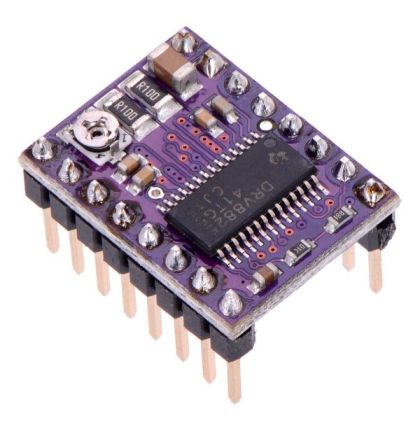
DRV8825 is een complete microstepping motor driver met ingebouwde “omzetter” voor een eenvoudige bediening. De v kan in vol, half, 1/4, 1/8 en 1/16 stap modi bipolaire stappenmotoren besturen, deze module werkt vanaf 8 V tot max. 35 V en kan 1.5A leveren per fase, en zelfs tot 2.2A indien gekoeld met een heat sink.
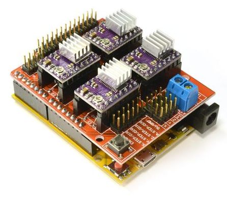
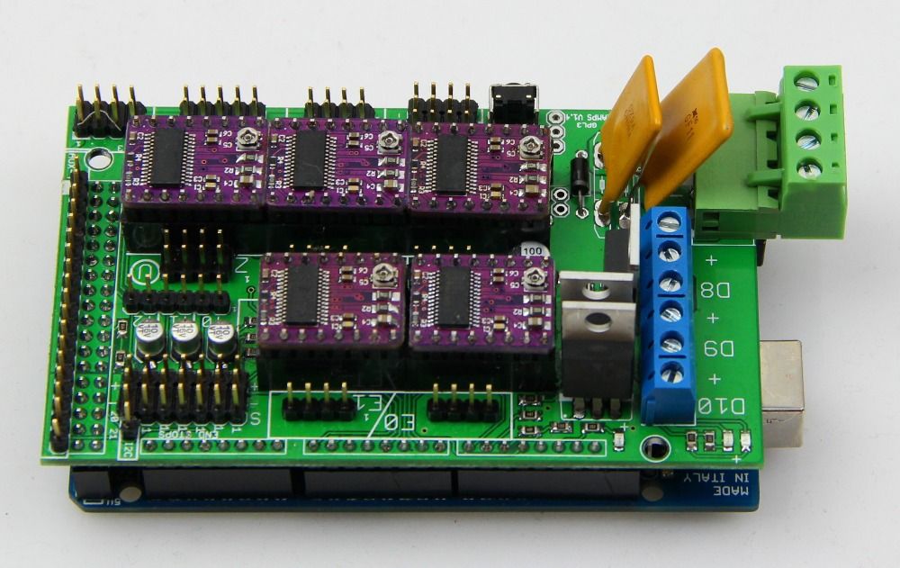
Deze modules (ook wel Polulu drivers genoemd) worden veelal geplaatst op Arduino Shields geschikt voor CNC en 3D Printing, zoals
Arduino CNC Shield:
RAMPS 1.4:
Het verschil is dat deze driver iets meer stroom kan verdragen dan de A4988 driver.
Meer informatie (ENG):
DRV8825 specificaties:
- PWM Microstepping Motor Driver
- Built-In Microstepping Indexer
- Five-Bit Winding Current Control Allows
- Up to 32 Current Levels
- Low MOSFET On-Resistance
- 2.5-A Maximum Drive Current at 24 V, 25°C
- Built-In 3.3-V Reference Output
- 8.2-V to 45-V Operating Supply Voltage Range
- Thermally Enhanced Surface Mount Package
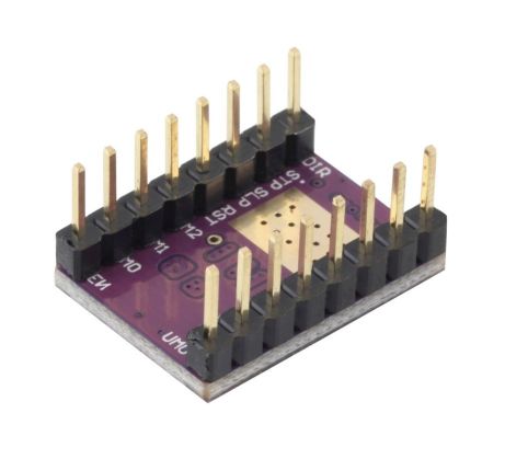
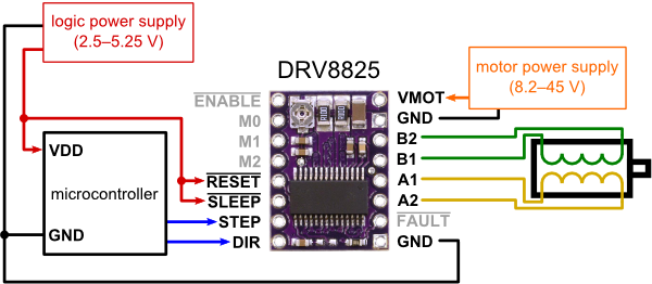
Pinout:
|
1 2 3 4 5 6 7 8 |
High(5V) when disabled, Low when enabled EN-| |-VMOT 12V (or voltage at 5A side of input power connector Set by Jumper MS1-| |-GND 0V Set by Jumper MS2-| |-1A ---------------| <Motor Coil A Set by Jumper MS3-| |-2A ---------------|____ Not used (tied to SLP) RST-| |-1B -----------------/ | <Motor Coil B Not used (tied to RST) SLP-| |-2B -------------------/ Pulse High for each step STEP-| |-VDD 5V Switches between High and Low when driven direction changes DIR-| |-GND 0V |
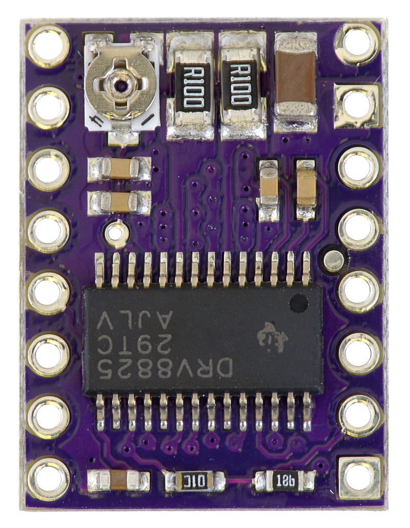
Closeup:
Overview
This product is a carrier board or breakout board for TI’s DRV8825 stepper motor driver; we therefore recommend careful reading of the DRV8825 datasheet (1MB pdf) before using this product. This stepper motor driver lets you control onebipolar stepper motor at up to 2.2 A output current per coil (see the Power Dissipation Considerations section below for more information). Here are some of the driver’s key features:
- Simple step and direction control interface
- Six different step resolutions: full-step, half-step, 1/4-step, 1/8-step, 1/16-step, and 1/32-step
- Adjustable current control lets you set the maximum current output with a potentiometer, which lets you use voltages above your stepper motor’s rated voltage to achieve higher step rates
- Intelligent chopping control that automatically selects the correct current decay mode (fast decay or slow decay)
- 45 V maximum supply voltage
- Built-in regulator (no external logic voltage supply needed)
- Can interface directly with 3.3 V and 5 V systems
- Over-temperature thermal shutdown, over-current shutdown, and under-voltage lockout
- Short-to-ground and shorted-load protection
- 4-layer, 2 oz copper PCB for improved heat dissipation
- Exposed solderable ground pad below the driver IC on the bottom of the PCB
- Module size, pinout, and interface match those of our A4988 stepper motor driver carriers in most respects (see the bottom of this page for more information)
This product ships with all surface-mount components—including the DRV8825 driver IC—installed as shown in the product picture.
Some unipolar stepper motors (e.g. those with six or eight leads) can be controlled by this driver as bipolar stepper motors. For more information, please see the frequently asked questions. Unipolar motors with five leads cannot be used with this driver.
Adjusting voltage output steppers
You have to adjust the Pololu Stepper Drivers before you can attach the motors. The low voltage Nema 17 Stepper Motors which can take a maximum current of 1.68A at a 2.8V. The Polulo A4988 Stepper Driver can drive up to 2A, this is far higher than the level required, resulting in the stepper motors running a lot cooler.
The best starting point is about 0.6x the rated current, this is the maximum current the stepper driver can output before requiring a heat sink ( n.b Heatsinks are already fitted).
You can calculate the approximate required Vref Voltage value by making the following calculations :
Vref = Stepper Motor Max Current x Factor Current x 0.4
Vref = 1.85A X 0.6A x 0.4 = 0.44V
So now select DC Current on your Multimeter to two decimal places.
The output voltage can be measured with a voltmeter on the pins shown below

You can adjust the output voltage by gently turning the potentiometer, it should be between 0.40 and 0.50V. If you want to raise the output, you have to turn the potentiometer clockwise, to lower the output turn counter clockwise. If the pololu board needs to drive two stepper motors (like the Prusa I3 Z-axis motors), you have to double the vRef output (eg 0.8 to 1V), otherwise only one motor will turn, or both motors won’t move at all.
24v Low Amperage Operation
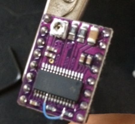
When using a DRV8825 board in a 24V system, microsteps can be lost in 1/32 mode if driving a stepper with VREF <0.8v (ie a 1.5A stepper). To prevent this, connect a fine patch wire between pin 19 (DECAY) on the DRV8825 (which is N/C on the stepper driver board) to the /FAULT pin on the carrier. This will supply logic power to DECAY, and put the DRV8825 in Fast Decay mode, appropriate for 24V low amperage systems.
Stepper Driver Testing
If you are not sure whether you have a problem with your RAMPS or the stepper drivers you can test that the driver is getting the power and signals it needs to work.
- Stepper motors getting too hot?
- Adjust the potentiometer (small screw) on the stepper driver by rotating the screw counterclockwise to decrease the current going to the stepper motor.
Use a meter of some sort to test the signals at one of the motor drivers. Be careful not to short anything out. You can use a (-) pad in AUX-1 for ground and test the voltage on VMOT, VDD, EN, STEP, and DIR. If all of these are working correctly then the stepper driver is likely bad.
Bronnen: reprap.org #1 / reprap.org #2 / reprap.org #3