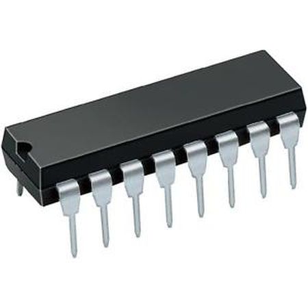
IC – CD4021 – Shift register input 8-bit
Hardware
Informatie (eng)
General Description
The CD4021BC is an 8-stage parallel input/serial output shift register. A parallel/serial control input enables individual JAM inputs to each of 8 stages. Q outputs are available from the sixth, seventh, and eighth stages. All outputs have equal source and sink current capabilities and conform to standard “B” series output drive. When the parallel/serial control input is in the logical “0” state, data is serially shifted into the register synchronously with the positive transition of the clock. When the parallel/serial control is in the logical “1” state, data is jammed into each stage of the register asynchronously with the clock. All inputs are protected against static discharge with diodes to VDD and VSS .
Features
* Wide supply voltage range: 3.0V to 15V
* High noise immunity: 0.45 V DD (typ.)
* Low power TTL compatibility
* Fan out of 2 driving 74L or 1 driving 74LS
* 5V–10V–15V parametric ratings
* Symmetrical output characteristics
* Maximum input leakage 1 µ A at 15V over full temperature range
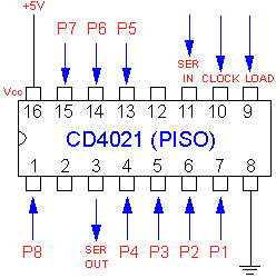
Pinout
Arduino
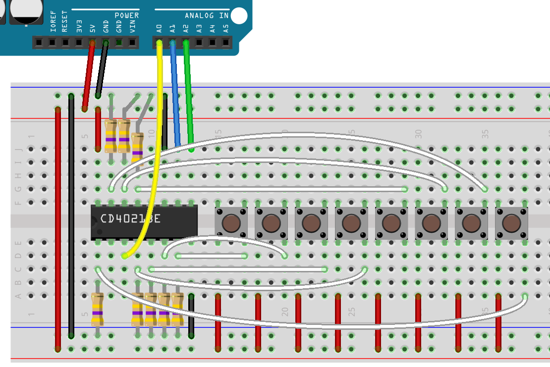
Sluit de IC aan volgens onderstaand overzicht:
Met onderstaand arduino script kun je de chip uitlezen:
|
1 2 3 4 5 6 7 8 9 10 11 12 13 14 15 16 17 18 19 20 21 22 23 24 25 26 27 28 29 30 31 32 33 34 35 36 37 38 39 40 41 42 43 44 45 46 47 48 49 50 51 52 53 54 55 56 57 58 59 60 61 62 63 64 65 66 67 68 69 70 71 72 73 74 75 76 77 78 79 |
int latchPin = A2; //Pin connected to PSC-Pin9 of CD4021 int clockPin = A1; //Pin connected to CLOCK-Pin10 of CD4021 int dataPin = A0; //Pin connected to SERIN-Pin11 of CD4021 int inputVal; // value read from inputs of CD49021 void setup() { Serial.begin(9600); //set pins to output so you can control the shift register pinMode(latchPin, OUTPUT); pinMode(clockPin, OUTPUT); pinMode(dataPin, INPUT); } void loop() { // read the inputs of the Shift Register inputVal = readCD4021(); Serial.print("Value is: BIN: "); Serial.print(inputVal, BIN); // display as Binary, MSB-LSB, D8-D1 Serial.print(" / DEC: "); Serial.println(inputVal); delay(250); // read and display once a second } int readCD4021(){ int value; // local variable to hold result of reading SR //Pulse the latch pin: //set it to 1 to collect parallel data digitalWrite(latchPin,1); //set it to 1 to collect parallel data, wait delayMicroseconds(20); //set it to 0 to transmit data serially digitalWrite(latchPin,0); //while the shift register is in serial mode //collect each shift register into a byte //the register attached to the chip comes in first value = shiftIn(dataPin, clockPin); return value; } ////// ----------------------------------------shiftIn function ///// just needs the location of the data pin and the clock pin ///// it returns a byte with each bit in the byte corresponding ///// to a pin on the shift register. leftBit 7 = Pin 7 / Bit 0 = Pin 0 byte shiftIn(int myDataPin, int myClockPin) { int i; int temp = 0; int pinState; byte myDataIn = 0; pinMode(myClockPin, OUTPUT); pinMode(myDataPin, INPUT); //we will be holding the clock pin high 8 times (0,..,7) at the //end of each time through the for loop //at the begining of each loop when we set the clock low, it will //be doing the necessary low to high drop to cause the shift //register's DataPin to change state based on the value //of the next bit in its serial information flow. //The register transmits the information about the pins from pin 7 to pin 0 //so that is why our function counts down for (i=7; i>=0; i--) { digitalWrite(myClockPin, 0); delayMicroseconds(0.2); temp = digitalRead(myDataPin); if (temp) { pinState = 1; //set the bit to 0 no matter what myDataIn = myDataIn | (1 << i); } else { pinState = 0; } digitalWrite(myClockPin, 1); } return myDataIn; } |
Console output:
|
1 2 3 4 5 6 7 8 9 10 11 12 13 14 15 16 17 18 19 20 21 22 23 24 25 26 27 28 29 30 31 |
Value is: BIN: 0 / DEC: 0 Value is: BIN: 0 / DEC: 0 Value is: BIN: 10 / DEC: 2 Value is: BIN: 10 / DEC: 2 Value is: BIN: 10 / DEC: 2 Value is: BIN: 100000 / DEC: 32 Value is: BIN: 100000 / DEC: 32 Value is: BIN: 100000 / DEC: 32 Value is: BIN: 1000000 / DEC: 64 Value is: BIN: 1000000 / DEC: 64 Value is: BIN: 10000 / DEC: 16 Value is: BIN: 10000 / DEC: 16 Value is: BIN: 10000 / DEC: 16 Value is: BIN: 10000 / DEC: 16 Value is: BIN: 10000 / DEC: 16 Value is: BIN: 1000 / DEC: 8 Value is: BIN: 1100 / DEC: 12 Value is: BIN: 1000 / DEC: 8 Value is: BIN: 1000 / DEC: 8 Value is: BIN: 110 / DEC: 6 Value is: BIN: 110 / DEC: 6 Value is: BIN: 1110 / DEC: 14 Value is: BIN: 1100 / DEC: 12 Value is: BIN: 1100 / DEC: 12 Value is: BIN: 1100 / DEC: 12 Value is: BIN: 1100 / DEC: 12 Value is: BIN: 1100 / DEC: 12 Value is: BIN: 100 / DEC: 4 Value is: BIN: 100 / DEC: 4 Value is: BIN: 100 / DEC: 4 Value is: BIN: 0 / DEC: 0 |
Bron(nen):
brainy-bits.com
Afmetingen
GEEN GEGEVENS
Schema
GEEN GEGEVENS
Teardown
GEEN GEGEVENS
Datasheet
Fritzing
GEEN GEGEVENS
Downloads
GEEN GEGEVENS


