Ciclop – Bouwinstructies
3D Scanner
Ciclop
Bouwinstructies
Informatie (ENG):
Parts
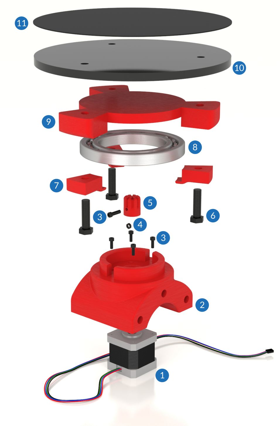
Disc structure
| Id | Name | Units | Description |
| 1 | Stepper motor | 1 | Nema 17 stepper motor with connector |
| 2 | Motor holder | 1 | Printable part that joins the stepper to the bearing. The stepper is held in place with M3 screws, while the bearing is pressed into place. |
| 3 | M3 x 10 mm Allen bolt | 5 | Four are used to fasten the stepper to its support and another to attach the stepper axis to the axis coupling. |
| 4 | M3 nut | 1 | Located on the axis coupling |
| 5 | Shaft coupling | 1 | Printable part that transmits the movement of the stepper to the disc. It is joined to the axis with a nut and an M3 bolt. |
| 6 | M8x30 mm bolt | 3 | Hex-headed bolts used for join the disc support to the bearing and the disc |
| 7 | Bearing clip | 3 | Printable part that connects the bearing to the disc with M8 nuts and bolts |
| 8 | Ball bearing 16014 | 1 | Supports the weight of the object so it does not act directly on the axis, enabling rotation |
| 9 | Disc holder | 1 | Printable part that connects the bearing to the disc using the printable clips. This piece transmits the rotation movement of the stepper axis to the disc |
| 10 | Methacrylate disc | 1 | 20 cm diameter and 8 mm thickness platform. It has 3 holes for the M8 bolts. It ensures that the surface is perfectly flat and tough |
| 11 | Non-slip surface | 1 | 20 cm diameter surface made of non-slip EPDM rubber which sticks to the disc. It increases the grip of the objects to be scanned |
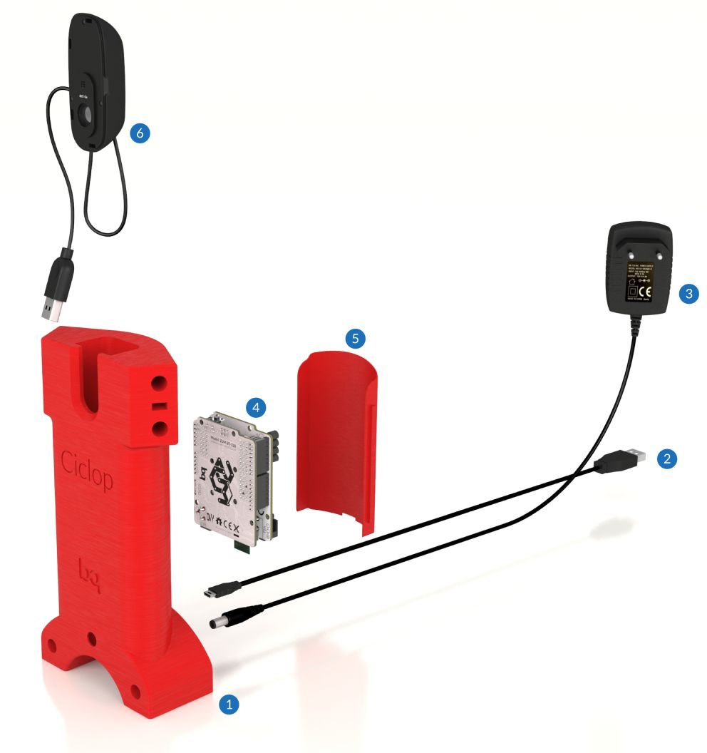
Camera structure
| Id | Name | Units | Description |
| 1 | Camera holder | 1 | Printable part with a hole on the top side for the camera. The electronics are housed in the interior of this part. |
| 2 | USB wire | 1 | Micro-USB to USB A type cable. It is used for communication with the electronics, although the communication via Bluetooth is also possible. |
| 3 | Power supply | 1 | DC 12V/1.5A power supply |
| 4 | Electronics | 1 | Controller board (ZUM-BT328) and power shield (ZUM SCAN). It runs the firmware that controls the stepper and lasers. |
| 5 | Back cover | 1 | Printable part that covers the back side of the camera holder, hiding the electronics |
| 6 | USB camera | 1 | Logitech C270 webcam. It fits at the top. The USB cable is hidden inside the structure. |
Laser structure
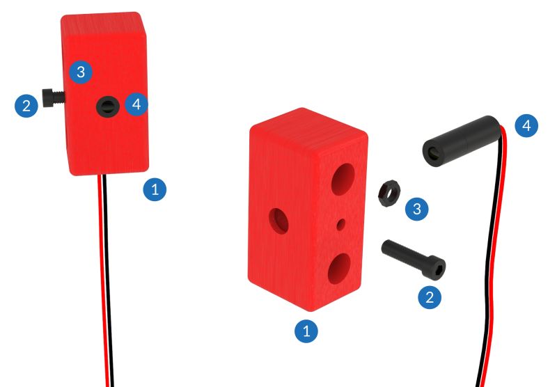
| 1 | Laser holder | 2 | Printable part with a hole where the laser is placed |
| 2 | M3 x 10 mm Allen bolt | 2 | Used to hold the laser to the support |
| 3 | M3 nut | 2 | Located inside the laser holder |
| 4 | Line laser | 2 | 650 nm Class 1 line laser with connector. It is attached to the structure with an M3 nut and a bolt |
Assembly
| Id | Name | Units | Description |
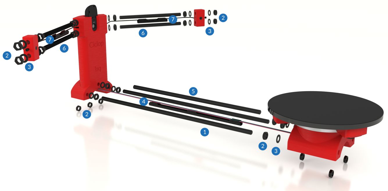
| 1 | M8 x 400mm threaded rods | 2 | They join the motor holder with the camera holder at the lateral sides |
| 2 | M8 nuts | 28 | Used to join the rods with the plastic parts |
| 3 | M8 washers | 18 | Used to prevent the contact between bolts and plastic parts |
| 4 | Motor wireway | 1 | Printable part that covers the motor wires. It is fitted onto the M8 x 292 rod. |
| 5 | M8 x 292mm threaded rod | 1 | It joins the motor holder with the camera holder at the central part of the piece |
| 6 | M8 x 170mm threaded rods | 4 | They join the laser holder with the camera holder |
| 7 | Laser wiring duct | 2 | Printable part that covers the laser wires. It is fitted onto the M8 x 170 rods. |
This kit also includes four rubber feet so that the device adheres more firmly to the surface it stands on. It also helps to reduce noise during scanning.
Once the scanner is assembled, check that the lasers are adjusted to emit a vertical light beam. However, this is not essential as their inclination will be determined during the calibration process.
At the end, the nuts and bolts must be well tightened to ensure that the final result is a rigid body with one degree of freedom, which means that no parts should be moving other than the disc.
Calibration pattern
| Id | Name | Units | Description |
| 1 | Pattern holder | 1 | Printable part with a groove where the pattern surface is placed |
| 2 | M3 nut | 2 | Located inside the pattern holder |
| 3 | M3 x 10 mm Allen bolt | 2 | M3 Allen bolt. It joins the methacrylate surface with the printable support |
| 4 | Methacrylate surface | 1 | Guarantees that the pattern is perfectly flat |
| 5 | Calibration pattern sticker | 1 | A “chessboard” type calibration pattern sticker, used in the camera calibration, laser triangulation and disc position and orientation |


