Condensator kleurcode tabel en nummer
Bron: electronics-tutorials.ws
Generally, the actual values of Capacitance, Voltage or Tolerance are marked onto the body of the capacitors in the form of alphanumeric characters.
However, when the value of the capacitance is of a decimal value problems arise with the marking of the “Decimal Point” as it could easily not be noticed resulting in a misreading of the actual capacitance value. Instead letters such as p (pico) or n (nano) are used in place of the decimal point to identify its position and the weight of the number.
For example, a capacitor can be labelled as, n47 = 0.47nF, 4n7 = 4.7nF or 47n = 47nF and so on. Also, sometimes capacitors are marked with the capital letter K to signify a value of one thousand pico-Farads, so for example, a capacitor with the markings of 100K would be 100 x 1000pF or 100nF.
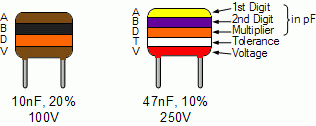
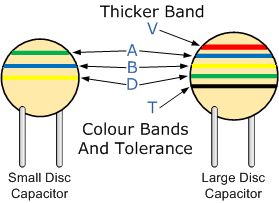
To reduce the confusion regarding letters, numbers and decimal points, an International colour coding scheme was developed many years ago as a simple way of identifying capacitor values and tolerances. It consists of coloured bands (in spectral order) known commonly as the Capacitor Colour Code system and whose meanings are illustrated below:
Capacitor Colour Code Table
| Band Colour | Digit A | Digit B | Multiplier D | Tolerance (T) > 10pf | Tolerance (T) < 10pf | Temperature Coefficient (TC) |
| Black | 0 | 0 | x1 | ± 20% | ± 2.0pF | |
| Brown | 1 | 1 | x10 | ± 1% | ± 0.1pF | -33×10-6 |
| Red | 2 | 2 | x100 | ± 2% | ± 0.25pF | -75×10-6 |
| Orange | 3 | 3 | x1,000 | ± 3% | -150×10-6 | |
| Yellow | 4 | 4 | x10,000 | ± 4% | -220×10-6 | |
| Green | 5 | 5 | x100,000 | ± 5% | ± 0.5pF | -330×10-6 |
| Blue | 6 | 6 | x1,000,000 | -470×10-6 | ||
| Violet | 7 | 7 | -750×10-6 | |||
| Grey | 8 | 8 | x0.01 | +80%,-20% | ||
| White | 9 | 9 | x0.1 | ± 10% | ± 1.0pF | |
| Gold | x0.1 | ± 5% | ||||
| Silver | x0.01 | ± 10% |
Capacitor Voltage Colour Code Table
| Band Colour | Voltage Rating (V) | ||||
| Type J | Type K | Type L | Type M | Type N | |
| Black | 4 | 100 | 10 | 10 | |
| Brown | 6 | 200 | 100 | 1.6 | |
| Red | 10 | 300 | 250 | 4 | 35 |
| Orange | 15 | 400 | 40 | ||
| Yellow | 20 | 500 | 400 | 6.3 | 6 |
| Green | 25 | 600 | 16 | 15 | |
| Blue | 35 | 700 | 630 | 20 | |
| Violet | 50 | 800 | |||
| Grey | 900 | 25 | 25 | ||
| White | 3 | 1000 | 2.5 | 3 | |
| Gold | 2000 | ||||
| Silver | |||||
Capacitor Voltage Reference
- Type J – Dipped Tantalum Capacitors.
- Type K – Mica Capacitors.
- Type L – Polyester/Polystyrene Capacitors.
- Type M – Electrolytic 4 Band Capacitors.
- Type N – Electrolytic 3 Band Capacitors.
An example of the use of capacitor colour codes is given as:
Metalised Polyester Capacitor
Disc & Ceramic Capacitor
The Capacitor Colour Code system was used for many years on unpolarised polyester and mica moulded capacitors. This system of colour coding is now obsolete but there are still many “old” capacitors around. Nowadays, small capacitors such as film or disk types conform to the BS1852 Standard and its new replacement, BS EN 60062, were the colours have been replaced by a letter or number coded system.
Generally the code consists of 2 or 3 numbers and an optional tolerance letter code to identify the tolerance. Where a two number code is used the value of the capacitor only is given in picofarads, for example, 47 = 47 pF and 100 = 100pF etc. A three letter code consists of the two value digits and a multiplier much like the resistor colour codes in the resistors section.
For example, the digits 471 = 47*10 = 470pF. Three digit codes are often accompanied by an additional tolerance letter code as given below.
Capacitor Tolerance Letter Codes Table
| Letter | B | C | D | F | G | J | K | M | Z | |
| Tolerance | C <10pF ±pF | 0.1 | 0.25 | 0.5 | 1 | 2 | ||||
| C >10pF ±% | 0.5 | 1 | 2 | 5 | 10 | 20 | +80 -20 |
Consider the capacitor below:
The capacitor on the left is of a ceramic disc type capacitor that has the code 473J printed onto its body. Then the 4 = 1st digit, the 7 = 2nd digit, the 3 is the multiplier in pico-Farads, pF and the letter J is the tolerance and this translates to: 47pF * 1,000 (3 zero’s) = 47,000 pF, 47nF or 0.047uF the J indicates a tolerance of +/- 5%
Then by just using numbers and letters as codes on the body of the capacitor we can easily determine the value of its capacitance either in Pico-farad’s, Nano-farads or Micro-farads and a list of these “international” codes is given in the following table along with their equivalent capacitances.
Capacitor Letter Codes Table
| Picofarad (pF) | Nanofarad (nF) | Microfarad (uF) | Code | Picofarad (pF) | Nanofarad (nF) | Microfarad (uF) | Code |
| 10 | 0.01 | 0.00001 | 100 | 4700 | 4.7 | 0.0047 | 472 |
| 15 | 0.015 | 0.000015 | 150 | 5000 | 5.0 | 0.005 | 502 |
| 22 | 0.022 | 0.000022 | 220 | 5600 | 5.6 | 0.0056 | 562 |
| 33 | 0.033 | 0.000033 | 330 | 6800 | 6.8 | 0.0068 | 682 |
| 47 | 0.047 | 0.000047 | 470 | 10000 | 10 | 0.01 | 103 |
| 100 | 0.1 | 0.0001 | 101 | 15000 | 15 | 0.015 | 153 |
| 120 | 0.12 | 0.00012 | 121 | 22000 | 22 | 0.022 | 223 |
| 130 | 0.13 | 0.00013 | 131 | 33000 | 33 | 0.033 | 333 |
| 150 | 0.15 | 0.00015 | 151 | 47000 | 47 | 0.047 | 473 |
| 180 | 0.18 | 0.00018 | 181 | 68000 | 68 | 0.068 | 683 |
| 220 | 0.22 | 0.00022 | 221 | 100000 | 100 | 0.1 | 104 |
| 330 | 0.33 | 0.00033 | 331 | 150000 | 150 | 0.15 | 154 |
| 470 | 0.47 | 0.00047 | 471 | 200000 | 200 | 0.2 | 254 |
| 560 | 0.56 | 0.00056 | 561 | 220000 | 220 | 0.22 | 224 |
| 680 | 0.68 | 0.00068 | 681 | 330000 | 330 | 0.33 | 334 |
| 750 | 0.75 | 0.00075 | 751 | 470000 | 470 | 0.47 | 474 |
| 820 | 0.82 | 0.00082 | 821 | 680000 | 680 | 0.68 | 684 |
| 1000 | 1.0 | 0.001 | 102 | 1000000 | 1000 | 1.0 | 105 |
| 1500 | 1.5 | 0.0015 | 152 | 1500000 | 1500 | 1.5 | 155 |
| 2000 | 2.0 | 0.002 | 202 | 2000000 | 2000 | 2.0 | 205 |
| 2200 | 2.2 | 0.0022 | 222 | 2200000 | 2200 | 2.2 | 225 |
| 3300 | 3.3 | 0.0033 | 332 | 3300000 | 3300 | 3.3 | 335 |
The next tutorial in our section about Capacitors, we look at connecting together Capacitor in Parallel and see that the total capacitance is the sum of the individual capacitors.


