IC – MAX232 – Dual EIA-232 driver and receiver
Hardware
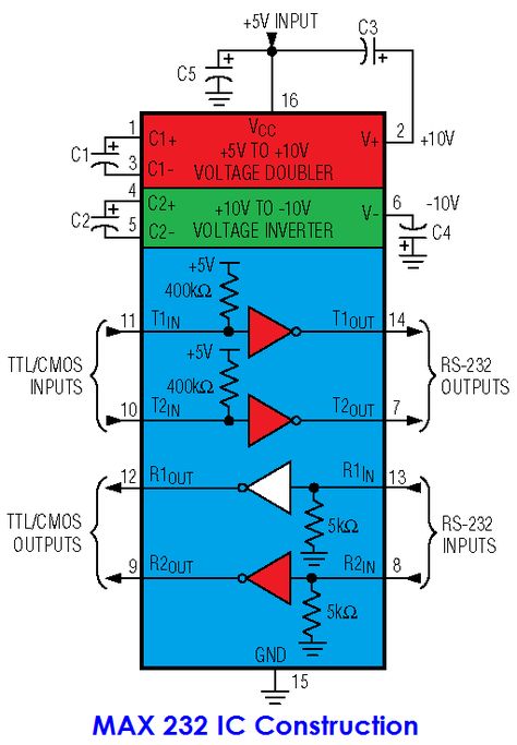
The MAX232 device is a dual driver/receiver that includes a capacitive voltage generator to supply TIA/EIA-232-F voltage levels from a single 5-V supply. Each receiver converts TIA/EIA-232-F inputs to 5-V TTL/CMOS levels. These receivers have a typical threshold of 1.3 V, a typical hysteresis of 0.5V, and can accept ±30-V inputs. Each driver converts TTL/CMOS input levels into TIA/EIA-232-F levels.
Pinout

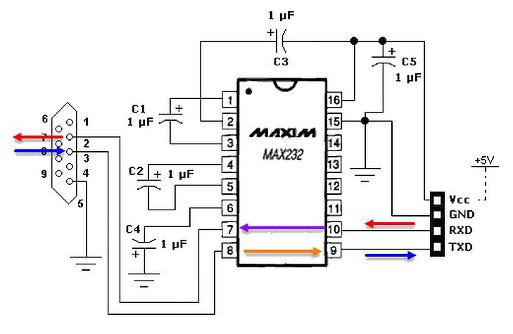
Schema
Example schematic using Rx/TX on pin 7,8,9,10
Example schematic using Rx/TX on pin 11,12,13,14
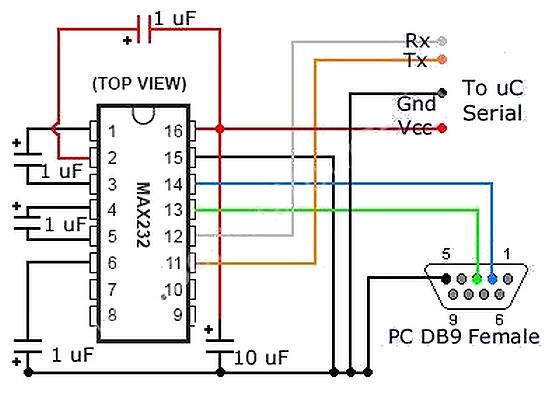
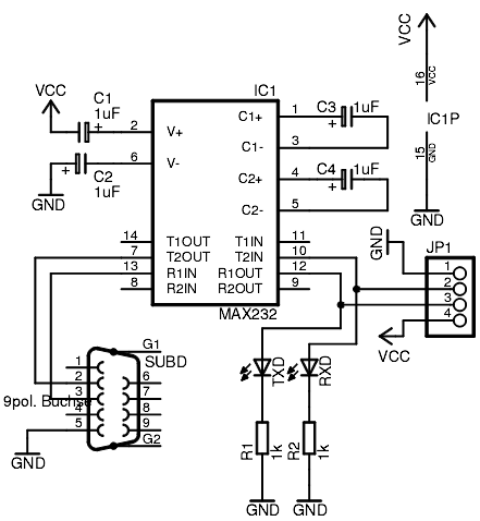
Example schematic with RX/TX LED’s
What is the purpose of the capacitors?
The 10uF capacitor shorts only AC voltages developing between VCC and GND: noise on the power supply. To DC, a capacitor is an open component!
When you power this MAX232 with single-voltage 5V supply, its V+ and V- pins are able to generate a dual supply: a positive voltage greater than 5V and a more or less equal but opposite negative voltage. How that kind of thing works is that an oscillator drives a network of diodes and capacitors: look up the term charge pump. The capacitors needed to make this charge pump work are connected to pins 1 and 3, and pins 4 and 5.
The 1uF capacitors on 2 and 6 (the V+ and V-) outputs, are just additional “rail caps” on this dual supply that is generated by the chip. They probably just do some further removal of ripple and noise from this generated supply. (To filter ripple, these capacitors don’t have to be large. Why? Because the internal oscillator for the charge pump probably works at a substantially higher frequency than 60 Hz.)
The use of the capacitor on pin 2 shows a slight deviation from the “Typical Operating Circuit” given in the Texas Instruments datasheet (Figure 4). In the datasheet, the pin is capacitively coupled to ground through a 1uF capacitor. Here you have it coupled to VCC. That does not matter much, because both VCC and GND are AC ground.
However, this configuration is not a mistake. It appears in the original Maxim datasheets for this device!
One important clue in the TI datasheet is a note that this device is compatible with another company’s existing product (and so is not a TI house design). It behooves us to look at the Maxim data sheet in addition to the TI one. That datasheet contains a lot more discussion and numerous additional diagrams.