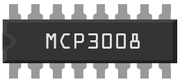
IC – MCP3008 – A/D Converter 10-bit 8 channel SPI
Hardware
Een analoog-digitaalomzetter of AD-converter (ADC) zet een analoog signaal, bijvoorbeeld een spraaksignaal, om in een digitaal signaal.
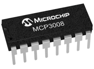
De MCP3008 heeft 8 analoge ingangen en is met een SPI interface uit te lezen op een Arduino, Raspberry Pi, ESP8266
De MCP zet een analoge voltage om in een getal tussen de 0 en 1023 (10 bit)
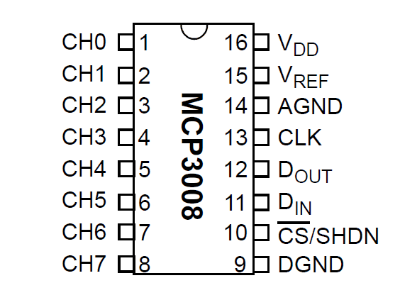
Pinout
Arduino
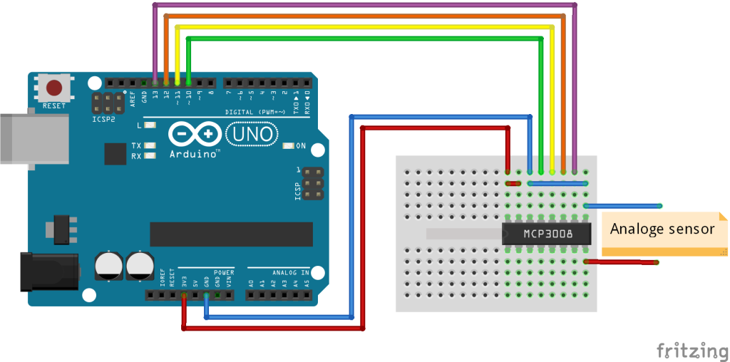
Sluit de IC aan volgens onderstaand overzicht:
| Arduino pin: | MCP3008 pin: |
|---|---|
| 3.3v...5v | VDD (pin 16) |
| 3.3v...5v | VREF (pin 15) |
| GND | AGND (pin 14) |
| GND | DGND (pin 9) |
| D9 | CLK (pin 13) |
| D10 | Dout (pin 12) |
| D11 | Din (pin 11) |
| D12 | CS/SHDN (pin 10) |
Met onderstaand arduino script kun je de chip uitlezen, met “adc.readADC(0)” lees je een ingang uit (0 = kanaal 1).
|
1 2 3 4 5 6 7 8 9 10 11 12 13 14 15 16 17 18 19 |
#include <MCP3008.h> // define pin connections #define CLOCK_PIN 9 #define MISO_PIN 10 #define MOSI_PIN 11 #define CS_PIN 12 // put pins inside MCP3008 constructor MCP3008 adc(CLOCK_PIN, MOSI_PIN, MISO_PIN, CS_PIN); void setup() { Serial.begin(9600); // open serial port } void loop() { int val = adc.readADC(0); // read Chanel 0 from MCP3008 ADC Serial.println(val); } |
Arduino Library
Installatie van Arduino IDE libraries: Arduino info
Informatie (ENG):
MCP3008 is Arduino Library for communicating with MCP3008 Analog to digital converter. Created by Uros Petrevski, Nodesign.net 2013 Released into the public domain.
MCP3008 VDD -> 5V or 3.3V
MCP3008 VREF -> 5V or 3.3V
MCP3008 AGND -> GND
MCP3008 CLK -> arduino gpio
MCP3008 DOUT -> arduino gpio
MCP3008 DIN -> arduino gpio
MCP3008 CS -> arduino gpio
MCP3008 DGND -> GND
Example program
|
1 2 3 4 5 6 7 8 9 10 11 12 13 14 15 16 17 18 19 20 21 22 23 24 25 26 27 28 29 30 |
#include <MCP3008.h> // define pin connections #define CS_PIN 12 #define CLOCK_PIN 9 #define MOSI_PIN 11 #define MISO_PIN 10 // put pins inside MCP3008 constructor MCP3008 adc(CLOCK_PIN, MOSI_PIN, MISO_PIN, CS_PIN); void setup() { // open serial port Serial.begin(9600); } void loop() { int val = adc.readADC(0); // read Chanel 0 from MCP3008 ADC Serial.println(val); // iterate thru all channels /* for (int i=0; i<8; i++) { int val = adc.readADC(i); Serial.print(val); Serial.print("\t"); } Serial.println(""); */ } |
Raspberry Pi
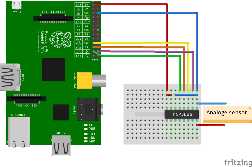
Sluit de IC aan zoals aangegeven op onderstaand schema:
| Raspberry Pi pin: | MCP3008 pin: |
|---|---|
| 3.3v...5v | VDD (pin 16) |
| 3.3v...5v | VREF (pin 15) |
| GND | AGND (pin 14) |
| GND | DGND (pin 9) |
| SCLK | CLK (pin 13) |
| MISO | Dout (pin 12) |
| MOSI | Din (pin 11) |
| CSO | CS/SHDN (pin 10) |
Ps. Altijd de pinout van je Raspberry Pi controleren, deze kan verschillen per versie.
Wat heb je nodig?
Met onderstaand python script kun je de chip uitlezen, met “read_spi(7)” lees je een ingang uit (7 = kanaal 8).
|
1 2 3 4 5 6 7 8 9 10 11 12 13 14 15 16 17 18 19 20 21 22 23 24 25 26 27 28 29 |
#!/usr/bin/python # Importeer bibliotheken import spidev import time # SPI intialisatie spi = spidev.SpiDev() spi.open(0,0) # Functie om de analoge waarde op te halen uit de chip def read_spi(channel): spidata = spi.xfer2([1,(8+channel)<<4,0]) print("Raw ADC: {}".format(spidata)) data = ((spidata[1] & 3) << 8) + spidata[2] return data try: while True: channeldata = read_spi(7) voltage = round(((channeldata * 3300) / 1024),0) print("Data (dec) {}".format(channeldata)) print("Data (bin) {}".format(('{0:010b}'.format(channeldata)))) print("Voltage (mV): {}".format(voltage)) print("--------------------") time.sleep(1) except KeyboardInterrupt: spi.close() |
Start het script met: sudo python mcp3008.py , druk op CTRL+C om het script te stoppen!
Dit is de output in de console:
|
1 2 3 4 5 6 7 8 9 10 11 12 13 14 15 16 17 18 19 20 21 22 23 24 25 26 27 28 29 30 31 32 33 34 35 |
Raw ADC: [0, 0, 202] Data (dec) 202 Data (bin) 0011001010 Voltage (mV): 650.0 -------------------- Raw ADC: [0, 0, 204] Data (dec) 204 Data (bin) 0011001100 Voltage (mV): 657.0 -------------------- Raw ADC: [0, 0, 208] Data (dec) 208 Data (bin) 0011010000 Voltage (mV): 670.0 -------------------- Raw ADC: [0, 0, 211] Data (dec) 211 Data (bin) 0011010011 Voltage (mV): 679.0 -------------------- Raw ADC: [0, 0, 213] Data (dec) 213 Data (bin) 0011010101 Voltage (mV): 686.0 -------------------- Raw ADC: [0, 0, 214] Data (dec) 214 Data (bin) 0011010110 Voltage (mV): 689.0 -------------------- Raw ADC: [0, 0, 216] Data (dec) 216 Data (bin) 0011011000 Voltage (mV): 696.0 -------------------- |
Bron:
raspberrypi-spy.co.uk
ESP8266
Ps. je hebt daarvoor wel een ESP-12, ESP-12E of ESP-12F module nodig, omdat je 4 GPIO poorten moet benutten voor de MCP3008.
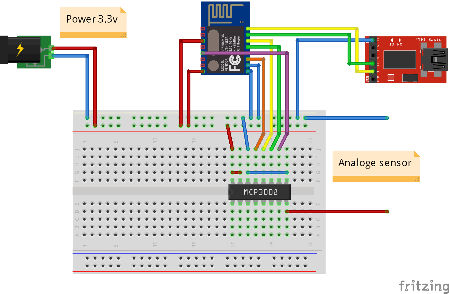
Sluit de IC aan volgens onderstaand schema:
| ESP8266 pin: | MCP3008 pin: | USB TTL pin: | Power: |
|---|---|---|---|
| 3.3v | VDD (pin 16) | 3.3v | |
| 3.3v | VREF (pin 15) | 3.3v | |
| GND | AGND (pin 14) | GND | GND |
| GND | DGND (pin 9) | GND | GND |
| GPIO2 | CLK (pin 13) | ||
| GPIO5 | Dout (pin 12) | ||
| GPIO4 | Din (pin 11) | ||
| GPIO14 | CS/SHDN (pin 10) | ||
| TX | RX | ||
| RX | TX |
Script (ArduinoIDE)
Wat heb je nodig?
1) ArduinoIDE software
2) ESP8266 ArduinoIDE board/omgeving
3) Arduino MCP3008 bibliotheek
Met onderstaande Arduino code kun je de kanalen uitlezen, hieronder het voorbeeld van kanaal 8:
|
1 2 3 4 5 6 7 8 9 10 11 12 13 14 15 16 17 18 19 |
#include <MCP3008.h> // Pin configuratie #define CLOCK_PIN 2 #define MISO_PIN 5 #define MOSI_PIN 4 #define CS_PIN 14 MCP3008 adc(CLOCK_PIN, MOSI_PIN, MISO_PIN, CS_PIN); // configureer de MCP3008 constructor. void setup() { Serial.begin(9600); // open de seriele poort. } void loop() { int val = adc.readADC(7); // lees kanaal 8 van de MCP3008 ADC. Serial.println(val); // print de waarde naar de console. delay(50); // wacht even } |
Afmetingen
GEEN GEGEVENS
Schema
GEEN GEGEVENS
Teardown
GEEN GEGEVENS
Datasheet
Fritzing
Downloads
GEEN GEGEVENS


