Prusa i3 Rework firmware – Marlin met RAMPS board

Marlin met RAMPS board
Prusa i3 Rework
Deze pagina beschrijft instellen van de software Marlin voor de 3D printer “Prusa i3 Rweork”, met behulp van de Arduino IDE.
Wat heb je nodig?
1) Arduino IDE
2) 3D Printer Firmware – Marlin
Installeren van Marlin
Nadat je ArduinoIDE hebt geïnstalleerd installeer je de “Marlin” folder vanuit het archief “Marlin v1.0.2-1” naar Arduino IDE
Dus de folder “Marlin-1.0.2-1 (2015-05-30).7zMarlin-1.0.2-1Marlin” naar “ArduinoIDEMarlin“.
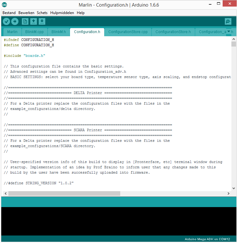
Start de Firmware op door op Marlin.ino te dubbelklikken, ArduinoIDE wordt dan opgestart, daarin zie je heel veel TAB’s en venstertjes openstaan:

Marlin configureren voor de Prusa i3 Rework (ENG)
RAMPS Motherboard
The next step will set the motherboard. In our case the chosen motherboard was’ ’33 = RAMPS 1.3 / 1.4 (Power outputs: Extruder, Fan, Bed) .
So we chose the value 33:
#define MOTHERBOARD 33
‘Note:’ If we had two print heads it would be 34.
‘Note on latest version of Marlin:’ If you use a newer version of the plates are in boards.h and writing The option will be #define MOTHERBOARD BOARD_RAMPS_13_EFB instead of #define MOTHERBOARD BOARD_ULTIMAKER’ ‘.
Thermistor
This step is to set the thermistor, as we are using 2 thermistors 100k, one for the heated bed and the other to the print head. The thermistor is who will get the temperature information.
So we chose a value of 1 for both:
|
1 2 3 4 |
#define TEMP_SENSOR_0 1 #define TEMP_SENSOR_1 0 #define TEMP_SENSOR_2 0 #define TEMP_SENSOR_BED 1 |
Note: ‘TEMP_SENSOR_0’ ‘refers to the print head thermistor and’ TEMP_SENSOR_BED for the heated platen. If using a thermistor 10k (not recommended for heated table) would have to choose another option.
Temperatures Min and Max
In this case you can set the minimum and maximum temperatures that the thermistor can detect .
minimum :
|
1 2 3 4 |
#define HEATER_0_MINTEMP 5 #define HEATER_1_MINTEMP 5 #define HEATER_2_MINTEMP 5 #define BED_MINTEMP 5 |
‘Note’ HEATER_0_MINTEMP refers to the print head thermistor and ‘BED_MINTEMP’ ‘for the heated platen. Maximum:
|
1 2 3 4 |
#define HEATER_0_MAXTEMP 275 #define HEATER_1_MAXTEMP 275 #define HEATER_2_MAXTEMP 275 #define BED_MAXTEMP 150 |
‘Note’ HEATER_0_MAXTEMP refers to the print head thermistor and ‘BED_MAXTEMP’ ‘for the heated platen.
Reverse movement of the motors
In these settings intentionally reverses some directions of the engines. When you have to make the first movement tests and verify that the motor is moving in the opposite direction can alter the value of true to false here.
|
1 2 3 4 5 6 |
#define INVERT_X_DIR true // for Mendel set to false, for Orca set to true #define INVERT_Y_DIR true // for Mendel set to true, for Orca set to false #define INVERT_Z_DIR true // for Mendel set to false, for Orca set to true #define INVERT_E0_DIR true // for direct drive extruder v9 set to true, for geared extruder set to false #define INVERT_E1_DIR false // for direct drive extruder v9 set to true, for geared extruder set to false #define INVERT_E2_DIR false // for direct drive extruder v9 set to true, for geared extruder set to false |
Position of endstops
If your limit switches (endstops) are the root cause when sends the printer to Home which in this case will be: X = 215mm (MAX), Y = 0 mm (MIN) and Z = 0 mm (MIN).
So the code to be applied is:
|
1 2 3 |
#define X_HOME_DIR 1 #define Y_HOME_DIR -1 #define Z_HOME_DIR -1 |
Where 1 is the maximum position of the X -1 and the minimum Y and Z.
Set size of the print area
By default the Prusa i3 is approximately a dimension of 215 mm X, Y, Z of 210 mm and 180 mm. If you have a larger print area you can always change the following values:
|
1 2 3 4 5 6 |
#define X_MAX_POS 215 #define X_MIN_POS 0 #define Y_MAX_POS 210 #define Y_MIN_POS 0 #define Z_MAX_POS 180 #define Z_MIN_POS 0 |
Step 10: Speed of the motor
You can set the speed of the motors, these settings can be improved at the time of calibration, but most of these values are defined in the following calculator http://prusaprinters.org/calculator/ Josef Prusa
|
1 2 3 4 |
// prusa i3 settings #define DEFAULT_AXIS_STEPS_PER_UNIT {80,80,4000,600} // default steps per unit for prusa i3 rework #define DEFAULT_MAX_FEEDRATE {500, 500, 2, 25} // (mm/sec) #define DEFAULT_MAX_ACCELERATION {2000,2000,20,1000} // X, Y, Z, E maximum start speed for accelerated moves. E default values are good for skeinforge 40+, for older versions raise them a lot. |
Note : these values work for the stepper drivers A4988. If you use DRV8825 drivers, the values must be changed to half .
At the time of calibration recommend to draw a mark on the desired axis (X , Y or Z) and moving 10 cm and see how mm it moves, then we can get the correct value DEFAULT_AXIS_STEPS_PER_UNIT comparing with the result.

