Stappenmotor aansturing module A4988
![]()
Stappenmotor aansturing module
Alegro’s A4988
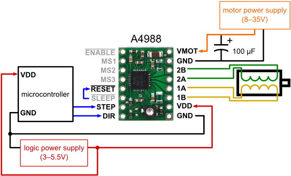
Hardware
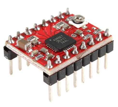
A4988 is een complete microstepping motor driver met ingebouwde “omzetter” voor een eenvoudige bediening. De A4988 kan in vol, half, 1/4, 1/8 en 1/16 stap modi bipolaire stappenmotoren besturen, deze module werkt vanaf 8 V tot max. 35 V en kan 1A leveren per fase, en zelfs tot 2A indien gekoeld met een heat sink.
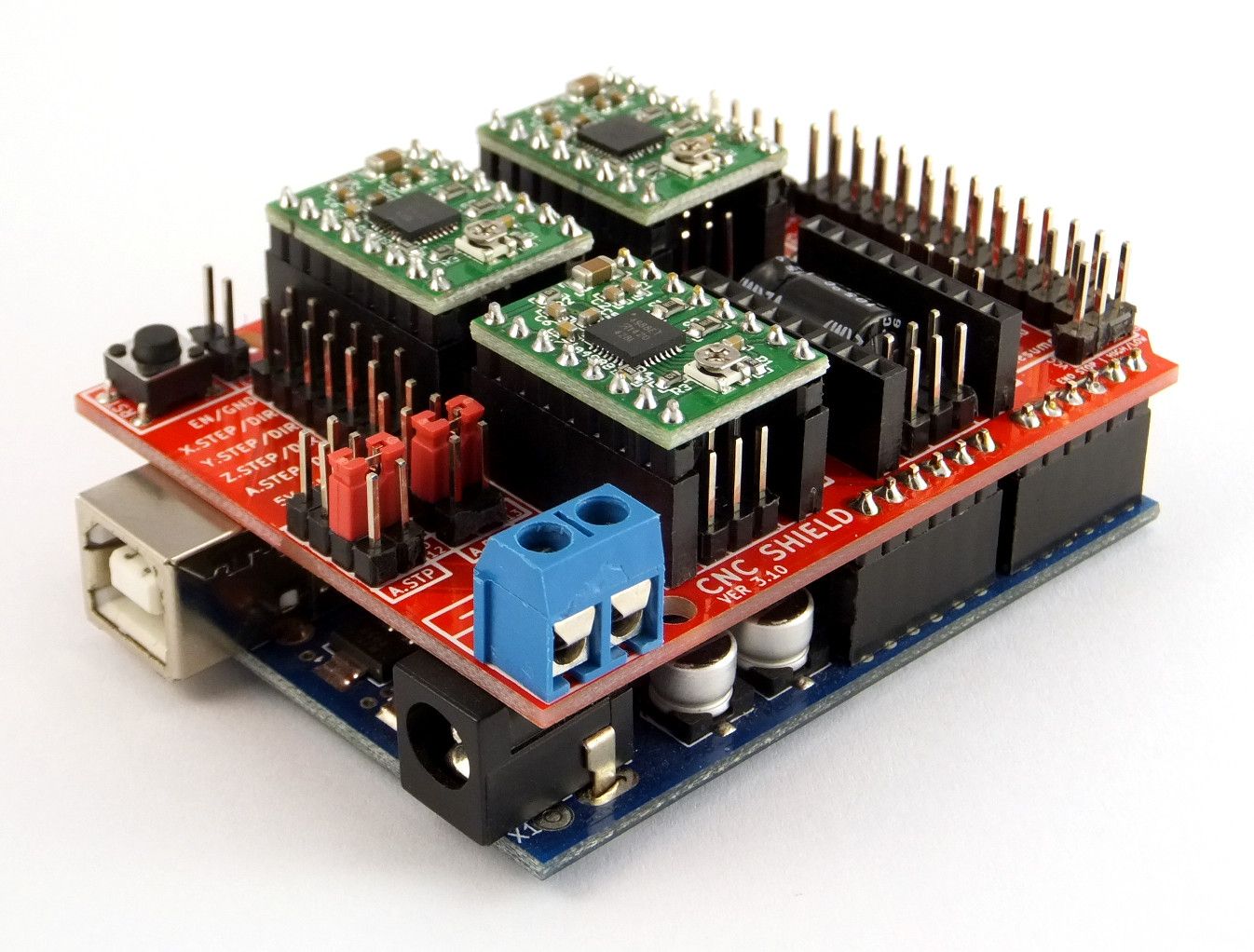
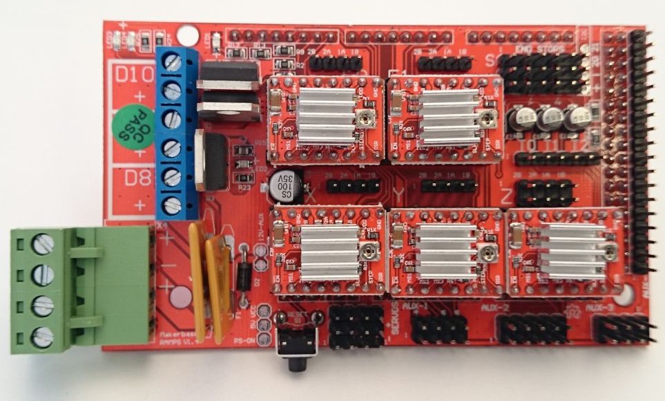
Deze modules (ook wel Polulu drivers genoemd) worden veelal geplaatst op Arduino Shields geschikt voor CNC en 3D Printing, zoals:
Arduino CNC Shield:
RAMPS 1.4:
A4988 specificaties:
– Low RDS (ON) uitgang
– Automatische stroom decay mode detectie / selectie
– Gemengd met langzame huidige verval modi
– Synchrone rectificatie voor weinig warmte
– interne UVLO
– 3.3 en 5 V compatibele Logic Supply
– Thermische uitschakeling circuit
– 5 selecteerbare stappen: vol, 1/2, 1/4, 1/8 en 1/16
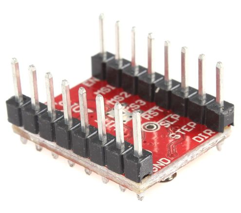
Pinout:
|
1 2 3 4 5 6 7 8 |
High(5V) when disabled, Low when enabled EN-| |-VMOT 12V (or voltage at 5A side of input power connector Set by Jumper MS1-| |-GND 0V Set by Jumper MS2-| |-1A ---------------| <Motor Coil A Set by Jumper MS3-| |-2A ---------------|____ Not used (tied to SLP) RST-| |-1B -----------------/ | <Motor Coil B Not used (tied to RST) SLP-| |-2B -------------------/ Pulse High for each step STEP-| |-VDD 5V Switches between High and Low when driven direction changes DIR-| |-GND 0V |
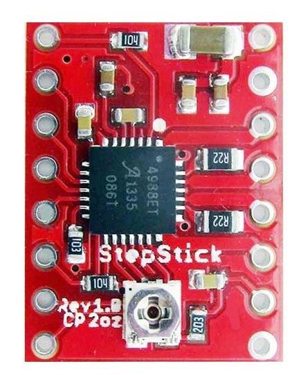
Closeup:
Meer informatie (ENG):
Overview
This product is a carrier board or breakout board for Allegro’s A4988 DMOS Microstepping Driver with Translator and Overcurrent Protection; we therefore recommend careful reading of the A4988 datasheet (1MB pdf) before using this product. This stepper motor driver lets you control one bipolar stepper motor at up to 2 A output current per coil (see the Power Dissipation Considerations section below for more information). Here are some of the driver’s key features:
- Simple step and direction control interface
- Five different step resolutions: full-step, half-step, quarter-step, eighth-step, and sixteenth-step
- Adjustable current control lets you set the maximum current output with a potentiometer, which lets you use voltages above your stepper motor’s rated voltage to achieve higher step rates
- Intelligent chopping control that automatically selects the correct current decay mode (fast decay or slow decay)
- Over-temperature thermal shutdown, under-voltage lockout, and crossover-current protection
- Short-to-ground and shorted-load protection
This product ships with all surface-mount components—including the A4988 driver IC—installed as shown in the product picture.
This product ships individually packaged with 0.1″ male header pins included but not soldered in; we also carry a version with male header pins already soldered in. For customers interested in higher volumes at lower unit costs, we offer a bulk-packaged version without header pins and a bulk-packaged version with header pins installed.
Note that we carry several stepper motor drivers that can be used as alternatives for this module. The Black Edition A4988 stepper motor driver carrier is available with approximately 20% better performance; except for thermal characteristics, the Black Edition and this (green) board are interchangeable. We also sell a larger version of the A4988 carrier that has reverse power protection on the main power input and built-in 5 V and 3.3 V voltage regulators that eliminate the need for separate logic and motor supplies. Our DRV8825 carrier offers approximately 50% better performance over a wider voltage range and with a few additional features, while our DRV8834 carrier works with motor supply voltages as low as 2.5 V; either of these boards can be used as a drop-in replacement for this driver in many applications.
Adjusting voltage output steppers
You have to adjust the Pololu Stepper Drivers before you can attach the motors. The low voltage Nema 17 Stepper Motors which can take a maximum current of 1.68A at a 2.8V. The Polulo A4988 Stepper Driver can drive up to 2A, this is far higher than the level required, resulting in the stepper motors running a lot cooler.
The best starting point is about 0.6x the rated current, this is the maximum current the stepper driver can output before requiring a heat sink ( n.b Heatsinks are already fitted).
You can calculate the approximate required Vref Voltage value by making the following calculations :
Vref = Stepper Motor Max Current x Factor Current x 0.4
Vref = 1.85A X 0.6A x 0.4 = 0.44V
So now select DC Current on your Multimeter to two decimal places.
The output voltage can be measured with a voltmeter on the pins shown below
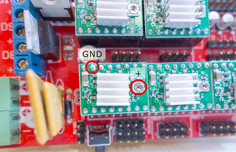
You can adjust the output voltage by gently turning the potentiometer, it should be between 0.40 and 0.50V. If you want to raise the output, you have to turn the potentiometer clockwise, to lower the output turn counter clockwise. If the pololu board needs to drive two stepper motors (like the Prusa I3 Z-axis motors), you have to double the vRef output (eg 0.8 to 1V), otherwise only one motor will turn, or both motors won’t move at all.
Stepper Driver Testing
If you are not sure whether you have a problem with your RAMPS or the stepper drivers you can test that the driver is getting the power and signals it needs to work.
- Stepper motors getting too hot?
- Adjust the potentiometer (small screw) on the stepper driver by rotating the screw counterclockwise to decrease the current going to the stepper motor.
Use a meter of some sort to test the signals at one of the motor drivers. Be careful not to short anything out. You can use a (-) pad in AUX-1 for ground and test the voltage on VMOT, VDD, EN, STEP, and DIR. If all of these are working correctly then the stepper driver is likely bad.
Bronnen: reprap.org #1 / reprap.org #2 / 3d.robbroek.nl