Builder 3D Mono firmware – Marlin v1.0.1 met Printrboard

Marlin met Printrboard
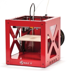
Builder 3D Mono
Arduino1.0.1-Teensy1.09-Marlin1.0.1
Deze pagina beschrijft het backuppen, bijwerken of instellen van de software Marlin voor de 3D printer “Prusa i3”, met behulp van de Arduino IDE.
Mijn “Builder 3D Mono 2.1010C” printerconfiguratie (hardware)
– Frame: Builder 3D Mono
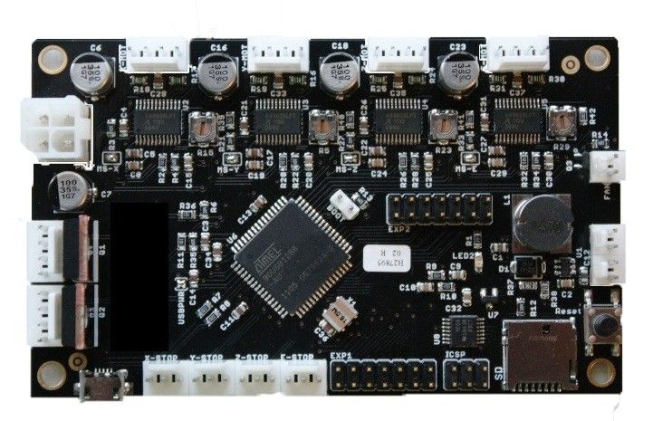
– Controller: Printrboard RevD.
– Stappenmotor X-as: NEMA 17 / 1.8deg/step / Tandwiel: GT2-16 tands.
– Stappenmotor Y-as: NEMA 17 / 1.8deg/step / Tandwiel: GT2-20 tands.
– Stappenmotors Z-as: NEMA 17 / 1.8deg/step / Verplaatst 40mm bij 5 omwentelingen (8mm/omw)
– Extruder: 1 kleur / Direct Drive
– Endstops: Magneet/Readcontacten (allemaal: Normally Open)
– Heated Bed: NVT.
– Temperatuursensor: 100K.
– Display: Mini LCD 4×20 (HD44780) met draaiknop, buzzer.
Wat heb je nodig?
Let op: voor deze printer zijn (vooralsnog) specifieke versies nodig:
1) Arduino IDE v1.0.1
2) Arduino IDE Teensy board addon v1.09 (installeer ook alle libraries)
3) Arduino IDE Teensy board at90usb1286 core addon
4) Arduino bibliotheek: LiquidTWI2 v1.23
5) 3D Printer Firmware – Marlin v1.0.1
Ps. onderaan deze pagina zijn totaal “voor geconfigureerde” pakketten te downloaden.
Installeren van Marlin
Nadat je ArduinoIDE hebt geïnstalleerd installeer je de “Marlin” folder vanuit het archief “Marlin v1.0.1” naar Arduino IDE.
Dus de folder “Marlin-1.0.1…….7z\Marlin-1.0.1\Marlin” naar “ArduinoIDE\Marlin“.
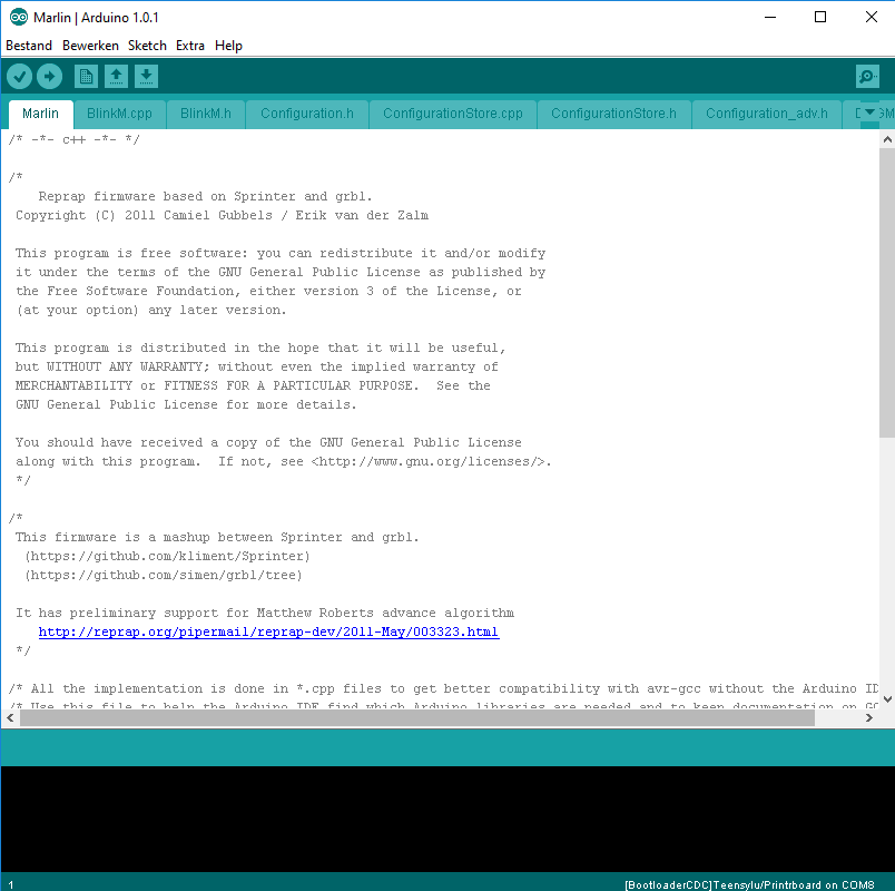
Start de firmware op door op Marlin.ino te openen vanaf Arduino v1.0.1 (dubbelklikken kan je eigen nieuwere Arduino IDE openenen), daarin zie je heel veel TAB’s en venstertjes openstaan:
Marlin configureren voor de Builder 3D
Let op: Dit stukje behandeld lang niet alle aspecten en mogelijkheden van de firmware, maar geeft de veranderingen in beeld voor de “Builder 3D” vanuit de standaard Marlin instellingen.
Board selecteren
De meeste instellingen staan in het bestand configuration.h, daar moet je ook het board selecteren in de regels:
|
1 2 3 4 5 |
// The following define selects which electronics board you have. // Please choose the name from boards.h that matches your setup #ifndef MOTHERBOARD #define MOTHERBOARD BOARD_ULTIMAKER #endif |
Ps. de aanwezige boards voor Marlin kun je vinden in het bestand boards.h
|
1 2 3 4 5 6 7 8 9 10 11 12 13 14 15 16 17 18 19 20 21 22 23 24 25 26 27 28 29 30 31 32 33 34 35 36 37 38 39 40 41 42 43 44 45 46 47 48 49 50 51 52 53 54 55 56 57 58 59 60 61 62 63 64 65 66 67 68 69 70 71 |
#define BOARD_GEN7_CUSTOM 10 // Gen7 custom (Alfons3 Version) "https://github.com/Alfons3/Generation_7_Electronics" #define BOARD_GEN7_12 11 // Gen7 v1.1, v1.2 #define BOARD_GEN7_13 12 // Gen7 v1.3 #define BOARD_GEN7_14 13 // Gen7 v1.4 #define BOARD_CNCONTROLS_11 111 // Cartesio CN Controls V11 #define BOARD_CNCONTROLS_12 112 // Cartesio CN Controls V12 #define BOARD_CHEAPTRONIC 2 // Cheaptronic v1.0 #define BOARD_CHEAPTRONIC_V2 21 // Cheaptronic v2.0 #define BOARD_SETHI 20 // Sethi 3D_1 #define BOARD_MIGHTYBOARD_REVE 200 // Makerbot Mightyboard Revision E #define BOARD_RAMPS_OLD 3 // MEGA/RAMPS up to 1.2 #define BOARD_RAMPS_13_EFB 33 // RAMPS 1.3 (Power outputs: Hotend, Fan, Bed) #define BOARD_RAMPS_13_EEB 34 // RAMPS 1.3 (Power outputs: Hotend0, Hotend1, Bed) #define BOARD_RAMPS_13_EFF 35 // RAMPS 1.3 (Power outputs: Hotend, Fan0, Fan1) #define BOARD_RAMPS_13_EEF 36 // RAMPS 1.3 (Power outputs: Hotend0, Hotend1, Fan) #define BOARD_RAMPS_13_SF 38 // RAMPS 1.3 (Power outputs: Spindle, Controller Fan) #define BOARD_FELIX2 37 // Felix 2.0+ Electronics Board (RAMPS like) #define BOARD_RIGIDBOARD 42 // Invent-A-Part RigidBoard #define BOARD_RIGIDBOARD_V2 52 // Invent-A-Part RigidBoard V2 #define BOARD_RAMPS_14_EFB 43 // RAMPS 1.4 (Power outputs: Hotend, Fan, Bed) #define BOARD_RAMPS_14_EEB 44 // RAMPS 1.4 (Power outputs: Hotend0, Hotend1, Bed) #define BOARD_RAMPS_14_EFF 45 // RAMPS 1.4 (Power outputs: Hotend, Fan0, Fan1) #define BOARD_RAMPS_14_EEF 46 // RAMPS 1.4 (Power outputs: Hotend0, Hotend1, Fan) #define BOARD_RAMPS_14_SF 48 // RAMPS 1.4 (Power outputs: Spindle, Controller Fan) #define BOARD_GEN6 5 // Gen6 #define BOARD_GEN6_DELUXE 51 // Gen6 deluxe #define BOARD_SANGUINOLOLU_11 6 // Sanguinololu < 1.2 #define BOARD_SANGUINOLOLU_12 62 // Sanguinololu 1.2 and above #define BOARD_MELZI 63 // Melzi #define BOARD_STB_11 64 // STB V1.1 #define BOARD_AZTEEG_X1 65 // Azteeg X1 #define BOARD_MELZI_MAKR3D 66 // Melzi with ATmega1284 (MaKr3d version) #define BOARD_AZTEEG_X3 67 // Azteeg X3 #define BOARD_AZTEEG_X3_PRO 68 // Azteeg X3 Pro #define BOARD_ULTIMAKER 7 // Ultimaker #define BOARD_ULTIMAKER_OLD 71 // Ultimaker (Older electronics. Pre 1.5.4. This is rare) #define BOARD_ULTIMAIN_2 72 // Ultimainboard 2.x (Uses TEMP_SENSOR 20) #define BOARD_3DRAG 77 // 3Drag Controller #define BOARD_K8200 78 // Velleman K8200 Controller (derived from 3Drag Controller) #define BOARD_K8400 79 // Velleman K8400 Controller (derived from 3Drag Controller) #define BOARD_TEENSYLU 8 // Teensylu #define BOARD_RUMBA 80 // Rumba #define BOARD_PRINTRBOARD 81 // Printrboard (AT90USB1286) #define BOARD_PRINTRBOARD_REVF 811 // Printrboard Revision F (AT90USB1286) #define BOARD_BRAINWAVE 82 // Brainwave (AT90USB646) #define BOARD_SAV_MKI 83 // SAV Mk-I (AT90USB1286) #define BOARD_TEENSY2 84 // Teensy++2.0 (AT90USB1286) - CLI compile: DEFINES=AT90USBxx_TEENSYPP_ASSIGNMENTS HARDWARE_MOTHERBOARD=84 make #define BOARD_BRAINWAVE_PRO 85 // Brainwave Pro (AT90USB1286) #define BOARD_GEN3_PLUS 9 // Gen3+ #define BOARD_GEN3_MONOLITHIC 22 // Gen3 Monolithic Electronics #define BOARD_MEGATRONICS 70 // Megatronics #define BOARD_MEGATRONICS_2 701 // Megatronics v2.0 #define BOARD_MINITRONICS 702 // Minitronics v1.0/1.1 #define BOARD_MEGATRONICS_3 703 // Megatronics v3.0 #define BOARD_MEGATRONICS_31 704 // Megatronics v3.1 #define BOARD_OMCA_A 90 // Alpha OMCA board #define BOARD_OMCA 91 // Final OMCA board #define BOARD_RAMBO 301 // Rambo #define BOARD_MINIRAMBO 302 // Mini-Rambo #define BOARD_SCOOVO_X9H 303 // abee Scoovo X9H #define BOARD_MEGACONTROLLER 310 // Mega controller #define BOARD_ELEFU_3 21 // Elefu Ra Board (v3) #define BOARD_5DPRINT 88 // 5DPrint D8 Driver Board #define BOARD_LEAPFROG 999 // Leapfrog #define BOARD_MKS_BASE 40 // MKS BASE 1.0 #define BOARD_MKS_13 47 // MKS v1.3 or 1.4 (maybe higher) #define BOARD_SAINSMART_2IN1 49 // Sainsmart 2-in-1 board #define BOARD_BAM_DICE 401 // 2PrintBeta BAM&DICE with STK drivers #define BOARD_BAM_DICE_DUE 402 // 2PrintBeta BAM&DICE Due with STK drivers #define BOARD_BQ_ZUM_MEGA_3D 503 // bq ZUM Mega 3D #define BOARD_ZRIB_V20 504 // zrib V2.0 control board (Chinese knock off RAMPS replica) |
We kiezen hier voor: BOARD_PRINTRBOARD
|
1 |
#define MOTHERBOARD BOARD_PRINTRBOARD |
Naam, URL en Firmware versie instellen
In het volgende stukje kan je de naam van de 3D printer instellen:
|
1 2 |
// Define this to set a custom name for your generic Mendel, //#define CUSTOM_MENDEL_NAME "This Mendel" |
Maar het is beter om dat in het bestand language.h aan te passen, daar kan je iets meer instellen zoals firmware versie en URL, voor de Builder 3D ziet dat stukje in language.h er dan zo uit:
(protocol in nu een verzonnen versie/naam)
Firmware versie:
#define PROTOCOL_VERSION "V2.3000X"
Naam en URL
|
1 2 3 4 5 6 7 8 |
#else #ifdef CUSTOM_MENDEL_NAME #define MACHINE_NAME CUSTOM_MENDEL_NAME #else #define MACHINE_NAME "Builder" #endif #define FIRMWARE_URL "http://www.3dprinter4U.com" #endif |
Stroomvoorziening instellen
In het volgende stukje kan je de stoomvoorziening instellen:
|
1 2 3 4 5 |
//// The following define selects which power supply you have. Please choose the one that matches your setup // 1 = ATX // 2 = X-Box 360 203Watts (the blue wire connected to PS_ON and the red wire to VCC) #define POWER_SUPPLY 1 |
De “Power supply” kan op 1 (ATX) blijven staan, dat geeft verder geen invloed op de werking van de printer.
Temperatuursensoren instellen (GEMETEN)
Het volgende stuk in behandeld de temperatuur instellingen:
|
1 2 3 4 5 6 7 8 9 10 11 12 13 14 15 16 17 18 19 20 21 22 23 24 25 26 27 28 29 30 31 32 33 34 35 36 37 |
//=========================================================================== //=============================Thermal Settings ============================ //=========================================================================== // //--NORMAL IS 4.7kohm PULLUP!-- 1kohm pullup can be used on hotend sensor, using correct resistor and table // //// Temperature sensor settings: // -2 is thermocouple with MAX6675 (only for sensor 0) // -1 is thermocouple with AD595 // 0 is not used // 1 is 100k thermistor - best choice for EPCOS 100k (4.7k pullup) // 2 is 200k thermistor - ATC Semitec 204GT-2 (4.7k pullup) // 3 is Mendel-parts thermistor (4.7k pullup) // 4 is 10k thermistor !! do not use it for a hotend. It gives bad resolution at high temp. !! // 5 is 100K thermistor - ATC Semitec 104GT-2 (Used in ParCan & J-Head) (4.7k pullup) // 6 is 100k EPCOS - Not as accurate as table 1 (created using a fluke thermocouple) (4.7k pullup) // 7 is 100k Honeywell thermistor 135-104LAG-J01 (4.7k pullup) // 71 is 100k Honeywell thermistor 135-104LAF-J01 (4.7k pullup) // 8 is 100k 0603 SMD Vishay NTCS0603E3104FXT (4.7k pullup) // 9 is 100k GE Sensing AL03006-58.2K-97-G1 (4.7k pullup) // 10 is 100k RS thermistor 198-961 (4.7k pullup) // 11 is 100k beta 3950 1% thermistor (4.7k pullup) // 12 is 100k 0603 SMD Vishay NTCS0603E3104FXT (4.7k pullup) (calibrated for Makibox hot bed) // 13 is 100k Hisens 3950 1% up to 300°C for hotend "Simple ONE " & "Hotend "All In ONE" // 20 is the PT100 circuit found in the Ultimainboard V2.x // 60 is 100k Maker's Tool Works Kapton Bed Thermistor beta=3950 // // 1k ohm pullup tables - This is not normal, you would have to have changed out your 4.7k for 1k // (but gives greater accuracy and more stable PID) // 51 is 100k thermistor - EPCOS (1k pullup) // 52 is 200k thermistor - ATC Semitec 204GT-2 (1k pullup) // 55 is 100k thermistor - ATC Semitec 104GT-2 (Used in ParCan & J-Head) (1k pullup) // // 1047 is Pt1000 with 4k7 pullup // 1010 is Pt1000 with 1k pullup (non standard) // 147 is Pt100 with 4k7 pullup // 110 is Pt100 with 1k pullup (non standard) |
Na het doormeten van de weerstand is dit een 100K ohm weerstand, dat geeft weerstand optie: 1
|
1 2 3 4 |
#define TEMP_SENSOR_0 1 #define TEMP_SENSOR_1 0 #define TEMP_SENSOR_2 0 #define TEMP_SENSOR_BED 0 |
Maximale temperaturen instellen
In het volgende stukje kun je maximale waarden van de temperaturen instellen.
In veel gevallen is boven de 250 graden meer dan voldoende voor het extruder systeem, zelfs voor ABS is dat meer dan genoeg:
|
1 2 3 4 5 6 7 |
// When temperature exceeds max temp, your heater will be switched off. // This feature exists to protect your hotend from overheating accidentally, but *NOT* from thermistor short/failure! // You should use MINTEMP for thermistor short/failure protection. #define HEATER_0_MAXTEMP 250 #define HEATER_1_MAXTEMP 250 #define HEATER_2_MAXTEMP 250 #define BED_MAXTEMP 60 |
PID temperatuurinstellingen (VAN ORGINELE FIRMWARE UITGELEZEN)
PID gebruikt in pricipe een PWM functie en is daardoor veel beter dan BangBang mode (vol aan / vol uit)
De PID_FUNCTIONAL_RANGE kan op 20 worden ingesteld:
|
1 2 |
#define PID_FUNCTIONAL_RANGE 20 // If the temperature difference between the target temperature and the actual temperature // is more than PID_FUNCTIONAL_RANGE then the PID will be shut off and the heater will be set to min/max. |
Verder zie je daaronder nog de PID instellingen, voor de Builder 3D Mono zijn deze te achterhalen uit de oude firmware:
Dat geeft deze instellingen:
|
1 2 3 4 5 6 7 8 9 10 11 12 13 14 15 16 17 18 19 20 21 22 |
// If you are using a pre-configured hotend then you can use one of the value sets by uncommenting it // Builder 3D Mono #define DEFAULT_Kp 9.08 #define DEFAULT_Ki 0.42 #define DEFAULT_Kd 49.22 // Ultimaker // #define DEFAULT_Kp 22.2 // #define DEFAULT_Ki 1.08 // #define DEFAULT_Kd 114 // MakerGear // #define DEFAULT_Kp 7.0 // #define DEFAULT_Ki 0.1 // #define DEFAULT_Kd 12 // Mendel Parts V9 on 12V // #define DEFAULT_Kp 63.0 // #define DEFAULT_Ki 2.25 // #define DEFAULT_Kd 440 #endif // PIDTEMP |
Schakelfunctie Endstops instellen (GEMETEN)
In het volgende stukje word de schakelfunctie van de endstops behandeld.
De Builder 3D Mono maakt gebruik van magnetische reed-contacten, na doormeten zijn deze NO (normally open).
(in Marlin: NO = true / NC = false)
|
1 2 3 4 5 6 7 |
// The pullups are needed if you directly connect a mechanical endswitch between the signal and ground pins. const bool X_MIN_ENDSTOP_INVERTING = true; // set to true to invert the logic of the endstop. const bool Y_MIN_ENDSTOP_INVERTING = true; // set to true to invert the logic of the endstop. const bool Z_MIN_ENDSTOP_INVERTING = true; // set to true to invert the logic of the endstop. const bool X_MAX_ENDSTOP_INVERTING = true; // set to true to invert the logic of the endstop. const bool Y_MAX_ENDSTOP_INVERTING = true; // set to true to invert the logic of the endstop. const bool Z_MAX_ENDSTOP_INVERTING = true; // set to true to invert the logic of the endstop. |
Assen/motoren uitzetten wanneer niet gebruikt
Deze instelling zorgt ervoor dat de extruder niet bekracht blijft indien deze niet gebruikt word:
|
1 2 3 4 5 6 |
// Disables axis when it's not being used. #define DISABLE_X false #define DISABLE_Y false #define DISABLE_Z false #define DISABLE_E true// For all extruders #define DISABLE_INACTIVE_EXTRUDER true //disable only inactive extruders and keep active extruder enabled |
Bewegingsrichtingen instellen (GETEST)
In het volgende stukje worden de bewegingsrichtingen behandeld.
Na wat testen blijkt dat de Y-as omgedraaid moet worden (op true) t.o.v. de standaard Marlin instellingen:
|
1 2 3 4 5 6 |
#define INVERT_X_DIR true // for Mendel set to false, for Orca set to true #define INVERT_Y_DIR true // for Mendel set to true, for Orca set to false #define INVERT_Z_DIR true // for Mendel set to false, for Orca set to true #define INVERT_E0_DIR false // for direct drive extruder v9 set to true, for geared extruder set to false #define INVERT_E1_DIR false // for direct drive extruder v9 set to true, for geared extruder set to false #define INVERT_E2_DIR false // for direct drive extruder v9 set to true, for geared extruder set to false |
Maximale printgrensen instellen (GEMETEN)
Hier heb je een meetlint, rolmaat of duimstok voor nodig, meet de maximale waarden op in mm wat je op het printbed kan printen vanuit het nulpunt gemeten let hierbij ook op de grootte van de X-carrier etc.
Na wat meten zijn dit de afmetingen/waarden voor de Builder 3D Mono:
|
1 2 3 4 5 6 7 |
// Travel limits after homing #define X_MAX_POS 220 #define X_MIN_POS 0 #define Y_MAX_POS 210 #define Y_MIN_POS 0 #define Z_MAX_POS 170 #define Z_MIN_POS 0 |
Motor stappen en snelheden instellen (VAN ORGINELE FIRMWARE UITGELEZEN)
Hier heb je een aantal berekeningen voor nodig, maar is ook uit de oude firmware te halen, zie onder:
Berekeningen stappen per mm
Formule riem aandrijving (X-as):
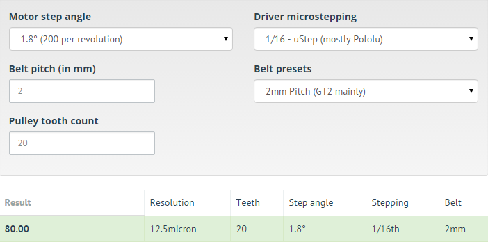
Het aantal stappen per unit wordt bepaald door het aantal stappen per omwenteling gedeeld door het aantal tanden van het tandwiel, gedeeld door de riem pitch (afstand tussen de tandjes)
Stappen per unit = Motor stappen per omwenteling / aantal tandwiel tanden / riem pitch
Bij de Builder 3D is er gebruikt op de X-as:
– NEMA 17 stappenmotor met 1,8 graad per rotatie.
– GT2-16 tands tandwiel met een GT2 riem (pitch = 2mm).
– Driver staat op 1/16 stap.
Motor stappen per rotatie: een rotatie is 360 graden / aantal graden per stap geeft: 360/ 1,8 = 200 stappen per omwenteling.
1/16 = 200 / 16 / 2 geeft: 1/16 = 6,25 , geeft: 1 = 100 , dat geeft het getal: 100
Ps. er is een handige website voor ingericht: prusaprinters.org calculator
Formule riem aandrijving (Y-as):
Het aantal stappen per unit wordt bepaald door het aantal stappen per omwenteling gedeeld door het aantal tanden van het tandwiel, gedeeld door de riem pitch (afstand tussen de tandjes)
Stappen per unit = Motor stappen per omwenteling / aantal tandwiel tanden / riem pitch
Bij de Builder 3D is er gebruikt op de Y-as:
– NEMA 17 stappenmotor met 1,8 graad per rotatie.
– GT2-20 tand tandwiel met een GT2 riem (pitch = 2mm).
– Driver staat op 1/16 stap.
Motor stappen per rotatie: een rotatie is 360 graden / aantal graden per stap geeft: 360/ 1,8 = 200 stappen per omwenteling.
1/16 = 200 / 20 / 2 geeft: 1/16 = 5 , geeft: 1 = 80 , dat geeft het getal: 80
Formule stang aandrijving (Z-as):
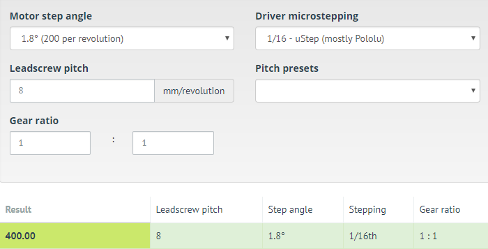
Het aantal stappen per unit wordt bepaald door het aantal stappen per omwenteling, gedeeld door de draadstang pitch (bijvoorbeeld de afstand van de verplaatsing van een moer bij in 1 omwenteling)
Stappen per unit = Motor stappen per omwenteling / draadstang pitch
Bij de Builder 3D is er gebruikt op de Z-as:
– NEMA 17 stappenmotor met 1,8 graad per rotatie.
– Onbekende M-maat, maar gemeten is dat de Z 40mm verplaatst bij 5 omwentelingen (8mm/omw)
– Driver staat op 1/16 stap.
Motor stappen per rotatie: een rotatie is 360 graden / aantal graden per stap geeft: 360/ 1,8 = 200 stappen per omwenteling.
1/16 = 200 / 8 geeft: 1/16 = 25 , geeft: 1 = 400 , dat geeft het getal: 400
Extruder aandrijving (E-as):
Bij de Builder 3D is er gebruikt op de E-as:
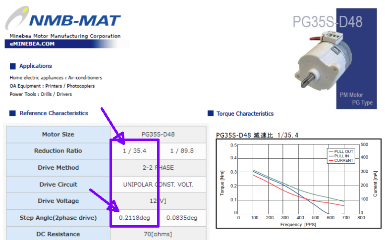
– Stappenmotor PG35S-D48-HHC2B met 0,2118 graad per rotatie, de gemonteerde gearbox verhouding is 1 / 35,4.
– Gemeten wiel diameter: 4,89 mm.
– Driver staat op 1/16 stap.
De formule is: Stappen per unit = Motor stappen per omwenteling * overzetverhouding / (wiel diameter * 3.1415)
Motor stappen per rotatie: een rotatie is 360 graden / aantal graden per stap geeft: 360 / 0,2118 = ca. 1700 stappen per omwenteling.
De gemonteerde gearbox verhouding geeft 1700 / 35,4 = 48 stappen per omwenteling.
1/16 = 48 / (wieldiameter * 3.1415) geeft 1/16 = 48 / 15,36 , geeft 1/16 = 3,125 , geeft: 1 = 50 , dat geeft het getal: 50
De configuratie geeft dan:
|
1 2 3 4 5 6 |
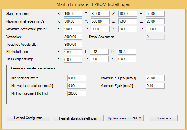
#define DEFAULT_AXIS_STEPS_PER_UNIT {100,80,400,50} // default steps per unit for builder #define DEFAULT_MAX_FEEDRATE {500, 500, 5, 25} // (mm/sec) #define DEFAULT_MAX_ACCELERATION {9000,9000,100,10000} // X, Y, Z, E maximum start speed for accelerated moves. E default values are good for skeinforge 40+, for older versions raise them a lot. #define DEFAULT_ACCELERATION 2000 // X, Y, Z and E max acceleration in mm/s^2 for printing moves #define DEFAULT_RETRACT_ACCELERATION 2000 // X, Y, Z and E max acceleration in mm/s^2 for retracts |
EEPROM instellingen
Met deze instellingen kan je eenvoudig met de EEPROM instellingen van je printer communiceren het neemt alleen wat meer programmaruimte in beslag!
|
1 2 3 4 5 6 7 8 9 10 |
// EEPROM // The microcontroller can store settings in the EEPROM, e.g. max velocity... // M500 - stores parameters in EEPROM // M501 - reads parameters from EEPROM (if you need reset them after you changed them temporarily). // M502 - reverts to the default "factory settings". You still need to store them in EEPROM afterwards if you want to. //define this to enable EEPROM support #define EEPROM_SETTINGS //to disable EEPROM Serial responses and decrease program space by ~1700 byte: comment this out: // please keep turned on if you can. #define EEPROM_CHITCHAT |
Preheat instellingen
Preheat instellingen staan ingebakken in de firmware en zijn te kiezen vanuit het menusysteem, veelal worden deze waarden gebruikt:
|
1 2 3 4 5 6 7 8 |
// Preheat Constants #define PLA_PREHEAT_HOTEND_TEMP 210 #define PLA_PREHEAT_HPB_TEMP 60 #define PLA_PREHEAT_FAN_SPEED 255 // Insert Value between 0 and 255 #define ABS_PREHEAT_HOTEND_TEMP 240 #define ABS_PREHEAT_HPB_TEMP 80 #define ABS_PREHEAT_FAN_SPEED 255 // Insert Value between 0 and 255 |
Ps. Zorg ervoor dat PLA_PREHEAT_HPB_TEMP niet de waarde van BED_MAXTEMP (eerder ingesteld) overschrijdt.
LCD en SD Support (GETEST)
De Builder 3D maakt gebruik van een “mini 20×4 schermpje, encoder en SD kaart” unit, we kunnen de SD instellingen hier instellen:
|
1 2 3 4 5 6 7 8 9 10 11 12 |
//LCD and SD support //#define ULTRA_LCD //general LCD support, also 16x2 //#define DOGLCD // Support for SPI LCD 128x64 (Controller ST7565R graphic Display Family) #define SDSUPPORT // Enable SD Card Support in Hardware Console #define SDSLOW // Use slower SD transfer mode (not normally needed - uncomment if you're getting volume init error) //#define SD_CHECK_AND_RETRY // Use CRC checks and retries on the SD communication //#define ENCODER_PULSES_PER_STEP 4 // Increase if you have a high resolution encoder //#define ENCODER_STEPS_PER_MENU_ITEM 5 // Set according to ENCODER_PULSES_PER_STEP or your liking //#define ULTIMAKERCONTROLLER //as available from the Ultimaker online store. //#define ULTIPANEL //the UltiPanel as on Thingiverse //#define LCD_FEEDBACK_FREQUENCY_HZ 1000 // this is the tone frequency the buzzer plays when on UI feedback. ie Screen Click //#define LCD_FEEDBACK_FREQUENCY_DURATION_MS 100 // the duration the buzzer plays the UI feedback sound. ie Screen Click |
GETEST: De Builder 3D maakt gebruik van de LiquidTWI2 bibliotheek voor de LCD en SD support, aanzetten van de sectie “PANELOLU LCD” wordt deze ingeladen.
GETEST: Encoder pulses, deze moet 4 per stap zijn om goed te functioneren.
GETEST: Frequentie kan gezet worden op 2000Hz, 10ms geeft een goede reactietijd in het menu!
|
1 2 3 4 5 6 7 8 9 10 11 12 13 14 15 16 17 18 19 20 21 22 23 24 25 26 27 |
// PANELOLU2 LCD with status LEDs, separate encoder and click inputs #define LCD_I2C_PANELOLU2 #ifdef LCD_I2C_PANELOLU2 // This uses the LiquidTWI2 library v1.2.3 or later ( https://github.com/lincomatic/LiquidTWI2 ) // Make sure the LiquidTWI2 directory is placed in the Arduino or Sketchbook libraries subdirectory. // (v1.2.3 no longer requires you to define PANELOLU in the LiquidTWI2.h library header file) // Note: The PANELOLU2 encoder click input can either be directly connected to a pin // (if BTN_ENC defined to != -1) or read through I2C (when BTN_ENC == -1). #define LCD_I2C_TYPE_MCP23017 #define LCD_I2C_ADDRESS 0x20 // I2C Address of the port expander #define LCD_USE_I2C_BUZZER //comment out to disable buzzer on LCD #define NEWPANEL #define ULTIPANEL #ifndef ENCODER_PULSES_PER_STEP #define ENCODER_PULSES_PER_STEP 4 #endif #ifndef ENCODER_STEPS_PER_MENU_ITEM #define ENCODER_STEPS_PER_MENU_ITEM 1 #endif #ifdef LCD_USE_I2C_BUZZER #define LCD_FEEDBACK_FREQUENCY_HZ 4000 #define LCD_FEEDBACK_FREQUENCY_DURATION_MS 10 #endif #endif |
Encoder Pin correcties
Bij de Builder 3D zijn wat andere pinnetjes gebruikt dan standaard, er moet daarom wat aangepast worden in de LiquidTWI2 biblotheek, bewerk het bestand: [arduino folder]\libraries\LiquidTWI2\LiquidTWI2.h en vervang het volgende stukje:
|
1 2 3 4 5 6 7 8 9 10 11 |
// Standard directional button bits #define BUTTON_UP 0x08 #define BUTTON_DOWN 0x08 //0x04 #define BUTTON_LEFT 0x08 //0x10 #define BUTTON_RIGHT 0x08 //0x02 #define BUTTON_SELECT 0x01 // Panelolu2 encoder button bits (which has only rotary encoder and encoder button) #define PANELOLU2_ENCODER_C 0x01 //0x04 // == encoder button #define PANELOLU2_ENCODER_B 0x04 //0x02 #define PANELOLU2_ENCODER_A 0x02 //0x01 |
Printrboard/Teensy2 FAST IO Fixes
Door wat pin inconsistentie e.d. ook wel te vinden op het internet zoals hier, heeft men een fix gemaakt!, bewerk fastio.h en vervang het hele bestand met onderstaande:
|
1 2 3 4 5 6 7 8 9 10 11 12 13 14 15 16 17 18 19 20 21 22 23 24 25 26 27 28 29 30 31 32 33 34 35 36 37 38 39 40 41 42 43 44 45 46 47 48 49 50 51 52 53 54 55 56 57 58 59 60 61 62 63 64 65 66 67 68 69 70 71 72 73 74 75 76 77 78 79 80 81 82 83 84 85 86 87 88 89 90 91 92 93 94 95 96 97 98 99 100 101 102 103 104 105 106 107 108 109 110 111 112 113 114 115 116 117 118 119 120 121 122 123 124 125 126 127 128 129 130 131 132 133 134 135 136 137 138 139 140 141 142 143 144 145 146 147 148 149 150 151 152 153 154 155 156 157 158 159 160 161 162 163 164 165 166 167 168 169 170 171 172 173 174 175 176 177 178 179 180 181 182 183 184 185 186 187 188 189 190 191 192 193 194 195 196 197 198 199 200 201 202 203 204 205 206 207 208 209 210 211 212 213 214 215 216 217 218 219 220 221 222 223 224 225 226 227 228 229 230 231 232 233 234 235 236 237 238 239 240 241 242 243 244 245 246 247 248 249 250 251 252 253 254 255 256 257 258 259 260 261 262 263 264 265 266 267 268 269 270 271 272 273 274 275 276 277 278 279 280 281 282 283 284 285 286 287 288 289 290 291 292 293 294 295 296 297 298 299 300 301 302 303 304 305 306 307 308 309 310 311 312 313 314 315 316 317 318 319 320 321 322 323 324 325 326 327 328 329 330 331 332 333 334 335 336 337 338 339 340 341 342 343 344 345 346 347 348 349 350 351 352 353 354 355 356 357 358 359 360 361 362 363 364 365 366 367 368 369 370 371 372 373 374 375 376 377 378 379 380 381 382 383 384 385 386 387 388 389 390 391 392 393 394 395 396 397 398 399 400 401 402 403 404 405 406 407 408 409 410 411 412 413 414 415 416 417 418 419 420 421 422 423 424 425 426 427 428 429 430 431 432 433 434 435 436 437 438 439 440 441 442 443 444 445 446 447 448 449 450 451 452 453 454 455 456 457 458 459 460 461 462 463 464 465 466 467 468 469 470 471 472 473 474 475 476 477 478 479 480 481 482 483 484 485 486 487 488 489 490 491 492 493 494 495 496 497 498 499 500 501 502 503 504 505 506 507 508 509 510 511 512 513 514 515 516 517 518 519 520 521 522 523 524 525 526 527 528 529 530 531 532 533 534 535 536 537 538 539 540 541 542 543 544 545 546 547 548 549 550 551 552 553 554 555 556 557 558 559 560 561 562 563 564 565 566 567 568 569 570 571 572 573 574 575 576 577 578 579 580 581 582 583 584 585 586 587 588 589 590 591 592 593 594 595 596 597 598 599 600 601 602 603 604 605 606 607 608 609 610 611 612 613 614 615 616 617 618 619 620 621 622 623 624 625 626 627 628 629 630 631 632 633 634 635 636 637 638 639 640 641 642 643 644 645 646 647 648 649 650 651 652 653 654 655 656 657 658 659 660 661 662 663 664 665 666 667 668 669 670 671 672 673 674 675 676 677 678 679 680 681 682 683 684 685 686 687 688 689 690 691 692 693 694 695 696 697 698 699 700 701 702 703 704 705 706 707 708 709 710 711 712 713 714 715 716 717 718 719 720 721 722 723 724 725 726 727 728 729 730 731 732 733 734 735 736 737 738 739 740 741 742 |
/* This code contibuted by Triffid_Hunter and modified by Kliment why double up on these macros? see http://gcc.gnu.org/onlinedocs/cpp/Stringification.html */ #ifndef _FASTIO_ARDUINO_H #define _FASTIO_ARDUINO_H #include <avr/io.h> /* utility functions */ #ifndef MASK /// MASKING- returns \f$2^PIN\f$ #define MASK(PIN) (1 << PIN) #endif /* magic I/O routines now you can simply SET_OUTPUT(STEP); WRITE(STEP, 1); WRITE(STEP, 0); */ /// Read a pin #define _READ(IO) ((bool)(DIO ## IO ## _RPORT & MASK(DIO ## IO ## _PIN))) /// write to a pin // On some boards pins > 0x100 are used. These are not converted to atomic actions. An critical section is needed. #define _WRITE_NC(IO, v) do { if (v) {DIO ## IO ## _WPORT |= MASK(DIO ## IO ## _PIN); } else {DIO ## IO ## _WPORT &= ~MASK(DIO ## IO ## _PIN); }; } while (0) #define _WRITE_C(IO, v) do { if (v) { \ CRITICAL_SECTION_START; \ {DIO ## IO ## _WPORT |= MASK(DIO ## IO ## _PIN); }\ CRITICAL_SECTION_END; \ }\ else {\ CRITICAL_SECTION_START; \ {DIO ## IO ## _WPORT &= ~MASK(DIO ## IO ## _PIN); }\ CRITICAL_SECTION_END; \ }\ }\ while (0) #define _WRITE(IO, v) do { if (&(DIO ## IO ## _RPORT) >= (uint8_t *)0x100) {_WRITE_C(IO, v); } else {_WRITE_NC(IO, v); }; } while (0) /// toggle a pin #define _TOGGLE(IO) do {DIO ## IO ## _RPORT = MASK(DIO ## IO ## _PIN); } while (0) /// set pin as input #define _SET_INPUT(IO) do {DIO ## IO ## _DDR &= ~MASK(DIO ## IO ## _PIN); } while (0) /// set pin as output #define _SET_OUTPUT(IO) do {DIO ## IO ## _DDR |= MASK(DIO ## IO ## _PIN); } while (0) /// check if pin is an input #define _GET_INPUT(IO) ((DIO ## IO ## _DDR & MASK(DIO ## IO ## _PIN)) == 0) /// check if pin is an output #define _GET_OUTPUT(IO) ((DIO ## IO ## _DDR & MASK(DIO ## IO ## _PIN)) != 0) /// check if pin is an timer #define _GET_TIMER(IO) ((DIO ## IO ## _PWM) // why double up on these macros? see http://gcc.gnu.org/onlinedocs/cpp/Stringification.html /// Read a pin wrapper #define READ(IO) _READ(IO) /// Write to a pin wrapper #define WRITE(IO, v) _WRITE(IO, v) /// toggle a pin wrapper #define TOGGLE(IO) _TOGGLE(IO) /// set pin as input wrapper #define SET_INPUT(IO) _SET_INPUT(IO) /// set pin as output wrapper #define SET_OUTPUT(IO) _SET_OUTPUT(IO) /// check if pin is an input wrapper #define GET_INPUT(IO) _GET_INPUT(IO) /// check if pin is an output wrapper #define GET_OUTPUT(IO) _GET_OUTPUT(IO) /// check if pin is an timer wrapper #define GET_TIMER(IO) _GET_TIMER(IO) /* ports and functions added as necessary or if I feel like it- not a comprehensive list! */ #endif #if defined(__AVR_AT90USB1286__)||defined(__AVR_AT90USB1287__) // SPI #define SCK DI21 #define MISO DIO11 #define MOSI DIO10 #define SS DIO8 // change for your board #define DEBUG_LED DIO31 /* led D5 red */ /* pins */ #define DIO0_PIN PIND0 #define DIO0_RPORT PIND #define DIO0_WPORT PORTD #define DIO0_PWM NULL #define DIO0_DDR DDRD #define DIO1_PIN PIND1 #define DIO1_RPORT PIND #define DIO1_WPORT PORTD #define DIO1_PWM NULL #define DIO1_DDR DDRD #define DIO2_PIN PIND2 #define DIO2_RPORT PIND #define DIO2_WPORT PORTD #define DIO2_PWM NULL #define DIO2_DDR DDRD #define DIO3_PIN PIND3 #define DIO3_RPORT PIND #define DIO3_WPORT PORTD #define DIO3_PWM NULL #define DIO3_DDR DDRD #define DIO4_PIN PIND4 #define DIO4_RPORT PIND #define DIO4_WPORT PORTD #define DIO4_PWM NULL #define DIO4_DDR DDRD #define DIO5_PIN PIND5 #define DIO5_RPORT PIND #define DIO5_WPORT PORTD #define DIO5_PWM NULL #define DIO5_DDR DDRD #define DIO6_PIN PIND6 #define DIO6_RPORT PIND #define DIO6_WPORT PORTD #define DIO6_PWM NULL #define DIO6_DDR DDRD #define DIO7_PIN PIND7 #define DIO7_RPORT PIND #define DIO7_WPORT PORTD #define DIO7_PWM NULL #define DIO7_DDR DDRD #define DIO8_PIN PINE0 #define DIO8_RPORT PINE #define DIO8_WPORT PORTE #define DIO8_PWM NULL #define DIO8_DDR DDRE #define DIO9_PIN PINE1 #define DIO9_RPORT PINE #define DIO9_WPORT PORTE #define DIO9_PWM NULL #define DIO9_DDR DDRE #define DIO10_PIN PINC0 #define DIO10_RPORT PINC #define DIO10_WPORT PORTC #define DIO10_PWM NULL #define DIO10_DDR DDRC #define DIO11_PIN PINC1 #define DIO11_RPORT PINC #define DIO11_WPORT PORTC #define DIO11_PWM NULL #define DIO11_DDR DDRC #define DIO12_PIN PINC2 #define DIO12_RPORT PINC #define DIO12_WPORT PORTC #define DIO12_PWM NULL #define DIO12_DDR DDRC #define DIO13_PIN PINC3 #define DIO13_RPORT PINC #define DIO13_WPORT PORTC #define DIO13_PWM NULL #define DIO13_DDR DDRC #define DIO14_PIN PINC4 #define DIO14_RPORT PINC #define DIO14_WPORT PORTC #define DIO14_PWM NULL #define DIO14_DDR DDRC #define DIO15_PIN PINC5 #define DIO15_RPORT PINC #define DIO15_WPORT PORTC #define DIO15_PWM NULL #define DIO15_DDR DDRC #define DIO16_PIN PINC6 #define DIO16_RPORT PINC #define DIO16_WPORT PORTC #define DIO16_PWM NULL #define DIO16_DDR DDRC #define DIO17_PIN PINC7 #define DIO17_RPORT PINC #define DIO17_WPORT PORTC #define DIO17_PWM NULL #define DIO17_DDR DDRC #define DIO18_PIN PINE6 #define DIO18_RPORT PINE #define DIO18_WPORT PORTE #define DIO18_PWM NULL #define DIO18_DDR DDRE #define DIO19_PIN PINE7 #define DIO19_RPORT PINE #define DIO19_WPORT PORTE #define DIO19_PWM NULL #define DIO19_DDR DDRE #define DIO20_PIN PINB0 #define DIO20_RPORT PINB #define DIO20_WPORT PORTB #define DIO20_PWM NULL #define DIO20_DDR DDRB #define DIO21_PIN PINB1 #define DIO21_RPORT PINB #define DIO21_WPORT PORTB #define DIO21_PWM NULL #define DIO21_DDR DDRB #define DIO22_PIN PINB2 #define DIO22_RPORT PINB #define DIO22_WPORT PORTB #define DIO22_PWM NULL #define DIO22_DDR DDRB #define DIO23_PIN PINB3 #define DIO23_RPORT PINB #define DIO23_WPORT PORTB #define DIO23_PWM NULL #define DIO23_DDR DDRB #define DIO24_PIN PINB4 #define DIO24_RPORT PINB #define DIO24_WPORT PORTB #define DIO24_PWM NULL #define DIO24_DDR DDRB #define DIO25_PIN PINB5 #define DIO25_RPORT PINB #define DIO25_WPORT PORTB #define DIO25_PWM NULL #define DIO25_DDR DDRB #define DIO26_PIN PINB6 #define DIO26_RPORT PINB #define DIO26_WPORT PORTB #define DIO26_PWM NULL #define DIO26_DDR DDRB #define DIO27_PIN PINB7 #define DIO27_RPORT PINB #define DIO27_WPORT PORTB #define DIO27_PWM NULL #define DIO27_DDR DDRB #define DIO28_PIN PINA0 #define DIO28_RPORT PINA #define DIO28_WPORT PORTA #define DIO28_PWM NULL #define DIO28_DDR DDRA #define DIO29_PIN PINA1 #define DIO29_RPORT PINA #define DIO29_WPORT PORTA #define DIO29_PWM NULL #define DIO29_DDR DDRA #define DIO30_PIN PINA2 #define DIO30_RPORT PINA #define DIO30_WPORT PORTA #define DIO30_PWM NULL #define DIO30_DDR DDRA #define DIO31_PIN PINA3 #define DIO31_RPORT PINA #define DIO31_WPORT PORTA #define DIO31_PWM NULL #define DIO31_DDR DDRA #define DIO32_PIN PINA4 #define DIO32_RPORT PINA #define DIO32_WPORT PORTA #define DIO32_PWM NULL #define DIO32_DDR DDRA #define DIO33_PIN PINA5 #define DIO33_RPORT PINA #define DIO33_WPORT PORTA #define DIO33_PWM NULL #define DIO33_DDR DDRA #define DIO34_PIN PINA6 #define DIO34_RPORT PINA #define DIO34_WPORT PORTA #define DIO34_PWM NULL #define DIO34_DDR DDRA #define DIO35_PIN PINA7 #define DIO35_RPORT PINA #define DIO35_WPORT PORTA #define DIO35_PWM NULL #define DIO35_DDR DDRA #define DIO36_PIN PINE4 #define DIO36_RPORT PINE #define DIO36_WPORT PORTE #define DIO36_PWM NULL #define DIO36_DDR DDRE #define DIO37_PIN PINE5 #define DIO37_RPORT PINE #define DIO37_WPORT PORTE #define DIO37_PWM NULL #define DIO37_DDR DDRE #define DIO38_PIN PINF0 #define DIO38_RPORT PINF #define DIO38_WPORT PORTF #define DIO38_PWM NULL #define DIO38_DDR DDRF #define DIO39_PIN PINF1 #define DIO39_RPORT PINF #define DIO39_WPORT PORTF #define DIO39_PWM NULL #define DIO39_DDR DDRF #define DIO40_PIN PINF2 #define DIO40_RPORT PINF #define DIO40_WPORT PORTF #define DIO40_PWM NULL #define DIO40_DDR DDRF #define DIO41_PIN PINF3 #define DIO41_RPORT PINF #define DIO41_WPORT PORTF #define DIO41_PWM NULL #define DIO41_DDR DDRF #define DIO42_PIN PINF4 #define DIO42_RPORT PINF #define DIO42_WPORT PORTF #define DIO42_PWM NULL #define DIO42_DDR DDRF #define DIO43_PIN PINF5 #define DIO43_RPORT PINF #define DIO43_WPORT PORTF #define DIO43_PWM NULL #define DIO43_DDR DDRF #define DIO44_PIN PINF6 #define DIO44_RPORT PINF #define DIO44_WPORT PORTF #define DIO44_PWM NULL #define DIO44_DDR DDRF #define DIO45_PIN PINF7 #define DIO45_RPORT PINF #define DIO45_WPORT PORTF #define DIO45_PWM NULL #define DIO45_DDR DDRF #define AIO0_PIN PINF0 #define AIO0_RPORT PINF #define AIO0_WPORT PORTF #define AIO0_PWM NULL #define AIO0_DDR DDRF #define AIO1_PIN PINF1 #define AIO1_RPORT PINF #define AIO1_WPORT PORTF #define AIO1_PWM NULL #define AIO1_DDR DDRF #define AIO2_PIN PINF2 #define AIO2_RPORT PINF #define AIO2_WPORT PORTF #define AIO2_PWM NULL #define AIO2_DDR DDRF #define AIO3_PIN PINF3 #define AIO3_RPORT PINF #define AIO3_WPORT PORTF #define AIO3_PWM NULL #define AIO3_DDR DDRF #define AIO4_PIN PINF4 #define AIO4_RPORT PINF #define AIO4_WPORT PORTF #define AIO4_PWM NULL #define AIO4_DDR DDRF #define AIO5_PIN PINF5 #define AIO5_RPORT PINF #define AIO5_WPORT PORTF #define AIO5_PWM NULL #define AIO5_DDR DDRF #define AIO6_PIN PINF6 #define AIO6_RPORT PINF #define AIO6_WPORT PORTF #define AIO6_PWM NULL #define AIO6_DDR DDRF #define AIO7_PIN PINF7 #define AIO7_RPORT PINF #define AIO7_WPORT PORTF #define AIO7_PWM NULL #define AIO7_DDR DDRF //-- Begin not supported by Teensyduino //-- don't use Arduino functions on these pins pinMode/digitalWrite/etc #define DIO46_PIN PINE2 #define DIO46_RPORT PINE #define DIO46_WPORT PORTE #define DIO46_PWM NULL #define DIO46_DDR DDRE #define DIO47_PIN PINE3 #define DIO47_RPORT PINE #define DIO47_WPORT PORTE #define DIO47_PWM NULL #define DIO47_DDR DDRE //-- end not supported by Teensyduino #undef PA0 #define PA0_PIN PINA0 #define PA0_RPORT PINA #define PA0_WPORT PORTA #define PA0_PWM NULL #define PA0_DDR DDRA #undef PA1 #define PA1_PIN PINA1 #define PA1_RPORT PINA #define PA1_WPORT PORTA #define PA1_PWM NULL #define PA1_DDR DDRA #undef PA2 #define PA2_PIN PINA2 #define PA2_RPORT PINA #define PA2_WPORT PORTA #define PA2_PWM NULL #define PA2_DDR DDRA #undef PA3 #define PA3_PIN PINA3 #define PA3_RPORT PINA #define PA3_WPORT PORTA #define PA3_PWM NULL #define PA3_DDR DDRA #undef PA4 #define PA4_PIN PINA4 #define PA4_RPORT PINA #define PA4_WPORT PORTA #define PA4_PWM NULL #define PA4_DDR DDRA #undef PA5 #define PA5_PIN PINA5 #define PA5_RPORT PINA #define PA5_WPORT PORTA #define PA5_PWM NULL #define PA5_DDR DDRA #undef PA6 #define PA6_PIN PINA6 #define PA6_RPORT PINA #define PA6_WPORT PORTA #define PA6_PWM NULL #define PA6_DDR DDRA #undef PA7 #define PA7_PIN PINA7 #define PA7_RPORT PINA #define PA7_WPORT PORTA #define PA7_PWM NULL #define PA7_DDR DDRA #undef PB0 #define PB0_PIN PINB0 #define PB0_RPORT PINB #define PB0_WPORT PORTB #define PB0_PWM NULL #define PB0_DDR DDRB #undef PB1 #define PB1_PIN PINB1 #define PB1_RPORT PINB #define PB1_WPORT PORTB #define PB1_PWM NULL #define PB1_DDR DDRB #undef PB2 #define PB2_PIN PINB2 #define PB2_RPORT PINB #define PB2_WPORT PORTB #define PB2_PWM NULL #define PB2_DDR DDRB #undef PB3 #define PB3_PIN PINB3 #define PB3_RPORT PINB #define PB3_WPORT PORTB #define PB3_PWM NULL #define PB3_DDR DDRB #undef PB4 #define PB4_PIN PINB4 #define PB4_RPORT PINB #define PB4_WPORT PORTB #define PB4_PWM NULL #define PB4_DDR DDRB #undef PB5 #define PB5_PIN PINB5 #define PB5_RPORT PINB #define PB5_WPORT PORTB #define PB5_PWM NULL #define PB5_DDR DDRB #undef PB6 #define PB6_PIN PINB6 #define PB6_RPORT PINB #define PB6_WPORT PORTB #define PB6_PWM NULL #define PB6_DDR DDRB #undef PB7 #define PB7_PIN PINB7 #define PB7_RPORT PINB #define PB7_WPORT PORTB #define PB7_PWM NULL #define PB7_DDR DDRB #undef PC0 #define PC0_PIN PINC0 #define PC0_RPORT PINC #define PC0_WPORT PORTC #define PC0_PWM NULL #define PC0_DDR DDRC #undef PC1 #define PC1_PIN PINC1 #define PC1_RPORT PINC #define PC1_WPORT PORTC #define PC1_PWM NULL #define PC1_DDR DDRC #undef PC2 #define PC2_PIN PINC2 #define PC2_RPORT PINC #define PC2_WPORT PORTC #define PC2_PWM NULL #define PC2_DDR DDRC #undef PC3 #define PC3_PIN PINC3 #define PC3_RPORT PINC #define PC3_WPORT PORTC #define PC3_PWM NULL #define PC3_DDR DDRC #undef PC4 #define PC4_PIN PINC4 #define PC4_RPORT PINC #define PC4_WPORT PORTC #define PC4_PWM NULL #define PC4_DDR DDRC #undef PC5 #define PC5_PIN PINC5 #define PC5_RPORT PINC #define PC5_WPORT PORTC #define PC5_PWM NULL #define PC5_DDR DDRC #undef PC6 #define PC6_PIN PINC6 #define PC6_RPORT PINC #define PC6_WPORT PORTC #define PC6_PWM NULL #define PC6_DDR DDRC #undef PC7 #define PC7_PIN PINC7 #define PC7_RPORT PINC #define PC7_WPORT PORTC #define PC7_PWM NULL #define PC7_DDR DDRC #undef PD0 #define PD0_PIN PIND0 #define PD0_RPORT PIND #define PD0_WPORT PORTD #define PD0_PWM NULL #define PD0_DDR DDRD #undef PD1 #define PD1_PIN PIND1 #define PD1_RPORT PIND #define PD1_WPORT PORTD #define PD1_PWM NULL #define PD1_DDR DDRD #undef PD2 #define PD2_PIN PIND2 #define PD2_RPORT PIND #define PD2_WPORT PORTD #define PD2_PWM NULL #define PD2_DDR DDRD #undef PD3 #define PD3_PIN PIND3 #define PD3_RPORT PIND #define PD3_WPORT PORTD #define PD3_PWM NULL #define PD3_DDR DDRD #undef PD4 #define PD4_PIN PIND4 #define PD4_RPORT PIND #define PD4_WPORT PORTD #define PD4_PWM NULL #define PD4_DDR DDRD #undef PD5 #define PD5_PIN PIND5 #define PD5_RPORT PIND #define PD5_WPORT PORTD #define PD5_PWM NULL #define PD5_DDR DDRD #undef PD6 #define PD6_PIN PIND6 #define PD6_RPORT PIND #define PD6_WPORT PORTD #define PD6_PWM NULL #define PD6_DDR DDRD #undef PD7 #define PD7_PIN PIND7 #define PD7_RPORT PIND #define PD7_WPORT PORTD #define PD7_PWM NULL #define PD7_DDR DDRD #undef PE0 #define PE0_PIN PINE0 #define PE0_RPORT PINE #define PE0_WPORT PORTE #define PE0_PWM NULL #define PE0_DDR DDRE #undef PE1 #define PE1_PIN PINE1 #define PE1_RPORT PINE #define PE1_WPORT PORTE #define PE1_PWM NULL #define PE1_DDR DDRE #undef PE2 #define PE2_PIN PINE2 #define PE2_RPORT PINE #define PE2_WPORT PORTE #define PE2_PWM NULL #define PE2_DDR DDRE #undef PE3 #define PE3_PIN PINE3 #define PE3_RPORT PINE #define PE3_WPORT PORTE #define PE3_PWM NULL #define PE3_DDR DDRE #undef PE4 #define PE4_PIN PINE4 #define PE4_RPORT PINE #define PE4_WPORT PORTE #define PE4_PWM NULL #define PE4_DDR DDRE #undef PE5 #define PE5_PIN PINE5 #define PE5_RPORT PINE #define PE5_WPORT PORTE #define PE5_PWM NULL #define PE5_DDR DDRE #undef PE6 #define PE6_PIN PINE6 #define PE6_RPORT PINE #define PE6_WPORT PORTE #define PE6_PWM NULL #define PE6_DDR DDRE #undef PE7 #define PE7_PIN PINE7 #define PE7_RPORT PINE #define PE7_WPORT PORTE #define PE7_PWM NULL #define PE7_DDR DDRE #undef PF0 #define PF0_PIN PINF0 #define PF0_RPORT PINF #define PF0_WPORT PORTF #define PF0_PWM NULL #define PF0_DDR DDRF #undef PF1 #define PF1_PIN PINF1 #define PF1_RPORT PINF #define PF1_WPORT PORTF #define PF1_PWM NULL #define PF1_DDR DDRF #undef PF2 #define PF2_PIN PINF2 #define PF2_RPORT PINF #define PF2_WPORT PORTF #define PF2_PWM NULL #define PF2_DDR DDRF #undef PF3 #define PF3_PIN PINF3 #define PF3_RPORT PINF #define PF3_WPORT PORTF #define PF3_PWM NULL #define PF3_DDR DDRF #undef PF4 #define PF4_PIN PINF4 #define PF4_RPORT PINF #define PF4_WPORT PORTF #define PF4_PWM NULL #define PF4_DDR DDRF #undef PF5 #define PF5_PIN PINF5 #define PF5_RPORT PINF #define PF5_WPORT PORTF #define PF5_PWM NULL #define PF5_DDR DDRF #undef PF6 #define PF6_PIN PINF6 #define PF6_RPORT PINF #define PF6_WPORT PORTF #define PF6_PWM NULL #define PF6_DDR DDRF #undef PF7 #define PF7_PIN PINF7 #define PF7_RPORT PINF #define PF7_WPORT PORTF #define PF7_PWM NULL #define PF7_DDR DDRF #endif #ifndef DIO0_PIN #error pins for this chip not defined in arduino.h! If you write an appropriate pin definition and have this firmware work on your chip, please submit a pull request #endif |
Printrboard PIN Instellingen (GETEST)
fastio.h
Doordat in het bestand fastio.h een aantal veranderingen zijn doorgevoerd moet in pins.h en Sd2PinMap.h ook het e.e.a. aangepast worden, je kan deze lijst aanhouden en met de Arduino kolom de pin definieren!
GETEST: Fan werkt alleen via pin 16.
WAARNEMING: Code-P West heeft het volgende aangesloten op de endstop pins (vlnr):
X / Y / Z / E (de orginele bedoeling)
X / ? / Z / Y (Code-P West)
Zodoende zit Y-STOP_PIN op pin 37.
OVERIG:
Encoder drukknop (EXP1 Linksonder):
– EXP1 pin 1 (SCL/PD0)
– EXP1 pin 3 (SCA/PD1)
Encoder Up/Down (EXP2 helemaal links):
– EXP2 pin 13
– EXP2 pin 14
bewerk pins.h en vervang het hele bestand met onderstaande:
|
1 2 3 4 5 6 7 8 9 10 11 12 13 14 15 16 17 18 19 20 21 22 23 24 25 26 27 28 29 30 31 32 33 34 35 36 37 38 39 40 41 42 43 44 45 46 47 48 49 50 51 52 53 54 55 56 57 58 59 60 61 62 63 64 65 66 67 68 69 70 71 72 73 74 75 76 77 78 79 80 81 82 83 84 85 86 87 88 89 90 91 92 93 94 95 96 97 98 99 100 101 102 103 104 105 106 107 108 109 110 111 112 113 114 115 116 117 118 119 120 121 122 123 124 125 126 127 128 129 130 131 132 133 134 135 136 137 138 139 140 141 142 143 144 145 146 147 148 149 150 151 152 153 154 155 156 157 158 159 160 161 162 163 164 165 166 167 168 |
#ifndef PINS_H #define PINS_H #include "boards.h" #if !MB(5DPRINT) #define X_MS1_PIN -1 #define X_MS2_PIN -1 #define Y_MS1_PIN -1 #define Y_MS2_PIN -1 #define Z_MS1_PIN -1 #define Z_MS2_PIN -1 #define E0_MS1_PIN -1 #define E0_MS2_PIN -1 #define E1_MS1_PIN -1 #define E1_MS2_PIN -1 #define DIGIPOTSS_PIN -1 #endif /**************************************************************************************** * Teensylu 0.7 / Printrboard pin assignments (AT90USB1286) * Requires the Teensyduino software with Teensy++ 2.0 selected in Arduino IDE! http://www.pjrc.com/teensy/teensyduino.html * See http://reprap.org/wiki/Printrboard for more info ****************************************************************************************/ #if MB(TEENSYLU) || MB(PRINTRBOARD) #define KNOWN_BOARD 1 #define AT90USB 1286 // Disable MarlinSerial etc. #ifndef __AVR_AT90USB1286__ #error Oops! Make sure you have 'Teensy++ 2.0' selected from the 'Tools -> Boards' menu. #endif #ifdef AT90USBxx_TEENSYPP_ASSIGNMENTS // use Teensyduino Teensy++2.0 pin assignments instead of Marlin traditional. #error These Teensylu/Printrboard assignments depend on traditional Marlin assignments, not AT90USBxx_TEENSYPP_ASSIGNMENTS in fastio.h #endif #define LARGE_FLASH true #define X_STEP_PIN 28 //0 #define X_DIR_PIN 29 //1 #define X_ENABLE_PIN 19 //39 #define Y_STEP_PIN 30 //2 #define Y_DIR_PIN 31 //3 #define Y_ENABLE_PIN 18 //38 #define Z_STEP_PIN 32 //4 #define Z_DIR_PIN 33 //5 #define Z_ENABLE_PIN 17 //23 #define E0_STEP_PIN 34 //6 #define E0_DIR_PIN 35 //7 #define E0_ENABLE_PIN 13 //19 #define HEATER_0_PIN 15 //21 // Extruder #define HEATER_1_PIN -1 #define HEATER_2_PIN -1 #define HEATER_BED_PIN 7 //20 // Bed #define FAN_PIN 16 // Fan #define UNUSED_1_PIN 20 // B0 // You may need to change FAN_PIN to 16 because Marlin isn't using fastio.h // for the fan and Teensyduino uses a different pin mapping. #if MOTHERBOARD == 8 // Teensylu #define X_STOP_PIN 47 //13 #define Y_STOP_PIN 37 //14 #define Z_STOP_PIN 36 //15 #define TEMP_0_PIN 1 //7 // Extruder / Analog pin numbering #define TEMP_BED_PIN -1 // Bed / Analog pin numbering #else // Printrboard #define X_STOP_PIN 47 #define Y_STOP_PIN 37 //8 #define Z_STOP_PIN 36 #define TEMP_0_PIN 1 // Extruder / Analog pin numbering #define TEMP_BED_PIN 0 // Bed / Analog pin numbering #endif #define TEMP_1_PIN -1 #define TEMP_2_PIN -1 #define SDPOWER -1 #define LED_PIN -1 #define PS_ON_PIN -1 #define KILL_PIN -1 #define ALARM_PIN -1 #define SDSS 40 //F2 #define BTN_ENC -1 #define BTN_EN1 11 //17 // PC1 #define BTN_EN2 12 //18 // PC2 #ifndef SDSUPPORT // these pins are defined in the SD library if building with SD support #define SCK_PIN 9 #define MISO_PIN 11 #define MOSI_PIN 10 #define SDSS 40 //F2 #define SDCARDDETECT -1 #endif #endif // TEENSYLU || PRINTRBOARD #ifndef KNOWN_BOARD #error Unknown MOTHERBOARD value in configuration.h #endif //List of pins which to ignore when asked to change by gcode, 0 and 1 are RX and TX, do not mess with those! #define _E0_PINS E0_STEP_PIN, E0_DIR_PIN, E0_ENABLE_PIN, HEATER_0_PIN, #if EXTRUDERS > 1 #define _E1_PINS E1_STEP_PIN, E1_DIR_PIN, E1_ENABLE_PIN, HEATER_1_PIN, #else #define _E1_PINS #endif #if EXTRUDERS > 2 #define _E2_PINS E2_STEP_PIN, E2_DIR_PIN, E2_ENABLE_PIN, HEATER_2_PIN, #else #define _E2_PINS #endif #ifdef X_STOP_PIN #if X_HOME_DIR < 0 #define X_MIN_PIN X_STOP_PIN #define X_MAX_PIN -1 #else #define X_MIN_PIN -1 #define X_MAX_PIN X_STOP_PIN #endif #endif #ifdef Y_STOP_PIN #if Y_HOME_DIR < 0 #define Y_MIN_PIN Y_STOP_PIN #define Y_MAX_PIN -1 #else #define Y_MIN_PIN -1 #define Y_MAX_PIN Y_STOP_PIN #endif #endif #ifdef Z_STOP_PIN #if Z_HOME_DIR < 0 #define Z_MIN_PIN Z_STOP_PIN #define Z_MAX_PIN -1 #else #define Z_MIN_PIN -1 #define Z_MAX_PIN Z_STOP_PIN #endif #endif #ifdef DISABLE_MAX_ENDSTOPS #define X_MAX_PIN -1 #define Y_MAX_PIN -1 #define Z_MAX_PIN -1 #endif #ifdef DISABLE_MIN_ENDSTOPS #define X_MIN_PIN -1 #define Y_MIN_PIN -1 #define Z_MIN_PIN -1 #endif #define SENSITIVE_PINS {0, 1, X_STEP_PIN, X_DIR_PIN, X_ENABLE_PIN, X_MIN_PIN, X_MAX_PIN, Y_STEP_PIN, Y_DIR_PIN, Y_ENABLE_PIN, Y_MIN_PIN, Y_MAX_PIN, Z_STEP_PIN, Z_DIR_PIN, Z_ENABLE_PIN, Z_MIN_PIN, Z_MAX_PIN, PS_ON_PIN, \ HEATER_BED_PIN, FAN_PIN, \ _E0_PINS _E1_PINS _E2_PINS \ analogInputToDigitalPin(TEMP_0_PIN), analogInputToDigitalPin(TEMP_1_PIN), analogInputToDigitalPin(TEMP_2_PIN), analogInputToDigitalPin(TEMP_BED_PIN) } #endif //__PINS_H |
Sd2PinMap.h
bewerk Sd2PinMap.h en vervang het hele bestand met onderstaande om zo de SD card module goed te activeren!:
|
1 2 3 4 5 6 7 8 9 10 11 12 13 14 15 16 17 18 19 20 21 22 23 24 25 26 27 28 29 30 31 32 33 34 35 36 37 38 39 40 41 42 43 44 45 46 47 48 49 50 51 52 53 54 55 56 57 58 59 60 61 62 63 64 65 66 67 68 69 70 71 72 73 74 75 76 77 78 79 80 81 82 83 84 85 86 87 88 89 90 91 92 93 94 95 96 97 98 99 100 101 102 103 104 105 106 107 108 109 110 111 112 113 114 115 116 117 118 119 120 121 122 123 124 125 126 127 128 129 130 131 132 133 134 135 136 137 138 139 140 141 142 143 144 145 146 147 148 149 |
/* Arduino SdFat Library * Copyright (C) 2010 by William Greiman * * This file is part of the Arduino SdFat Library * * This Library is free software: you can redistribute it and/or modify * it under the terms of the GNU General Public License as published by * the Free Software Foundation, either version 3 of the License, or * (at your option) any later version. * * This Library is distributed in the hope that it will be useful, * but WITHOUT ANY WARRANTY; without even the implied warranty of * MERCHANTABILITY or FITNESS FOR A PARTICULAR PURPOSE. See the * GNU General Public License for more details. * * You should have received a copy of the GNU General Public License * along with the Arduino SdFat Library. If not, see * <http://www.gnu.org/licenses/>. */ // Warning this file was generated by a program. #include "Marlin.h" #ifdef SDSUPPORT #ifndef Sd2PinMap_h #define Sd2PinMap_h #include <avr/io.h> //------------------------------------------------------------------------------ /** struct for mapping digital pins */ struct pin_map_t { volatile uint8_t* ddr; volatile uint8_t* pin; volatile uint8_t* port; uint8_t bit; }; //------------------------------------------------------------------------------ #if defined(__AVR_AT90USB646__)\ || defined(__AVR_AT90USB1286__) // Teensy++ 1.0 & 2.0 // Two Wire (aka I2C) ports //uint8_t const SDA_PIN = 24; // D1/ //uint8_t const SCL_PIN = 25; // D0 // SPI port uint8_t const SS_PIN = 40; // F2 was 20 b0 uint8_t const MOSI_PIN = 22; // B2 uint8_t const MISO_PIN = 23; // B3 uint8_t const SCK_PIN = 21; // B1 static const pin_map_t digitalPinMap[] = { {&DDRD, &PIND, &PORTD, 0}, // D0 0 {&DDRD, &PIND, &PORTD, 1}, // D1 1 {&DDRD, &PIND, &PORTD, 2}, // D2 2 {&DDRD, &PIND, &PORTD, 3}, // D3 3 {&DDRD, &PIND, &PORTD, 4}, // D4 4 {&DDRD, &PIND, &PORTD, 5}, // D5 5 {&DDRD, &PIND, &PORTD, 6}, // D6 6 {&DDRD, &PIND, &PORTD, 7}, // D7 7 {&DDRE, &PINE, &PORTE, 0}, // E0 8 {&DDRE, &PINE, &PORTE, 1}, // E1 9 {&DDRC, &PINC, &PORTC, 0}, // C0 10 {&DDRC, &PINC, &PORTC, 1}, // C1 11 {&DDRC, &PINC, &PORTC, 2}, // C2 12 {&DDRC, &PINC, &PORTC, 3}, // C3 13 {&DDRC, &PINC, &PORTC, 4}, // C4 14 {&DDRC, &PINC, &PORTC, 5}, // C5 15 {&DDRC, &PINC, &PORTC, 6}, // C6 16 {&DDRC, &PINC, &PORTC, 7}, // C7 17 {&DDRE, &PINE, &PORTE, 6}, // E6 18 {&DDRE, &PINE, &PORTE, 7}, // E7 19 {&DDRB, &PINB, &PORTB, 0}, // B0 20 {&DDRB, &PINB, &PORTB, 1}, // B1 21 {&DDRB, &PINB, &PORTB, 2}, // B2 22 {&DDRB, &PINB, &PORTB, 3}, // B3 23 {&DDRB, &PINB, &PORTB, 4}, // B4 24 {&DDRB, &PINB, &PORTB, 5}, // B5 25 {&DDRB, &PINB, &PORTB, 6}, // B6 26 {&DDRB, &PINB, &PORTB, 7}, // B7 27 {&DDRA, &PINA, &PORTA, 0}, // A0 28 {&DDRA, &PINA, &PORTA, 1}, // A1 29 {&DDRA, &PINA, &PORTA, 2}, // A2 30 {&DDRA, &PINA, &PORTA, 3}, // A3 31 {&DDRA, &PINA, &PORTA, 4}, // A4 32 {&DDRA, &PINA, &PORTA, 5}, // A5 33 {&DDRA, &PINA, &PORTA, 6}, // A6 34 {&DDRA, &PINA, &PORTA, 7}, // A7 35 {&DDRE, &PINE, &PORTE, 4}, // E4 36 {&DDRE, &PINE, &PORTE, 5}, // E5 37 {&DDRF, &PINF, &PORTF, 0}, // F0 38 {&DDRF, &PINF, &PORTF, 1}, // F1 39 {&DDRF, &PINF, &PORTF, 2}, // F2 40 {&DDRF, &PINF, &PORTF, 3}, // F3 41 {&DDRF, &PINF, &PORTF, 4}, // F4 42 {&DDRF, &PINF, &PORTF, 5}, // F5 43 {&DDRF, &PINF, &PORTF, 6}, // F6 44 {&DDRF, &PINF, &PORTF, 7} // F7 45 }; #else // defined(__AVR_AT90USB1286__) #error unknown chip #endif //------------------------------------------------------------------------------ static const uint8_t digitalPinCount = sizeof(digitalPinMap)/sizeof(pin_map_t); uint8_t badPinNumber(void) __attribute__((error("Pin number is too large or not a constant"))); static inline __attribute__((always_inline)) bool getPinMode(uint8_t pin) { if (__builtin_constant_p(pin) && pin < digitalPinCount) { return (*digitalPinMap[pin].ddr >> digitalPinMap[pin].bit) & 1; } else { return badPinNumber(); } } static inline __attribute__((always_inline)) void setPinMode(uint8_t pin, uint8_t mode) { if (__builtin_constant_p(pin) && pin < digitalPinCount) { if (mode) { *digitalPinMap[pin].ddr |= 1 << digitalPinMap[pin].bit; } else { *digitalPinMap[pin].ddr &= ~(1 << digitalPinMap[pin].bit); } } else { badPinNumber(); } } static inline __attribute__((always_inline)) bool fastDigitalRead(uint8_t pin) { if (__builtin_constant_p(pin) && pin < digitalPinCount) { return (*digitalPinMap[pin].pin >> digitalPinMap[pin].bit) & 1; } else { return badPinNumber(); } } static inline __attribute__((always_inline)) void fastDigitalWrite(uint8_t pin, uint8_t value) { if (__builtin_constant_p(pin) && pin < digitalPinCount) { if (value) { *digitalPinMap[pin].port |= 1 << digitalPinMap[pin].bit; } else { *digitalPinMap[pin].port &= ~(1 << digitalPinMap[pin].bit); } } else { badPinNumber(); } } #endif // Sd2PinMap_h #endif |
Uploaden van de firmware
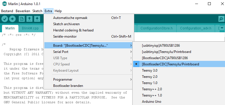
Voor het uploaden van de firmware kies het volgende board:
[#/3dprinter/builder3dmono/firmware_printrboard” ]


